RD33775ADSTEVB Quick Start Guides
Contents of this document
-
Out of the Box
-
Get Hardware
-
Configure Hardware
Sign in to save your progress. Don't have an account? Create one.
Purchase your RD33775ADSTEVB
1. Out of the Box
The NXP analog product development boards provide an easy-to-use platform for evaluating NXP products. The boards support a range of analog, mixed-signal and power solutions. They incorporate monolithic integrated circuits and system-in-package devices that use proven high-volume technology. NXP products offer longer battery life, a smaller form factor, reduced component counts, lower cost and improved performance in powering state-of-the-art systems.
This page will guide you through the process of setting up and using the RD33775ADSTEVB board.
1.1 Kit Content and Packing List
The RD33775ADSTEVB kit contents include:
- Assembled and tested evaluation board/module in anti-static bag
- Cell terminal cable
- Transformer physical layer (TPL) cable
2. Get Hardware
2.1 Board Features
- It can be used together with S32K3 controller board to build up a distributed evaluation system
- Transformer-based isolation between boards
- Based on NXP core layout for MC33775A; core layout is used for NXP internal electromagnetic compatibility (EMC) and hotplug tests
- Four layer board, all components are assembled only on the top side
- All eight negative temperature coefficient (NTC) sensor inputs are available
- I2C-bus EEPROM
2.2 Board Description
The RD33775ADSTEVB is a hardware evaluation tool in support of MC33775A device of NXP. The MC33775A is a battery cell controller that monitors up to 14 lithium-ion battery cells. It is designed for use in both automotive and industrial applications. The device performs analog-to-digital conversions on the differential cell voltages. It is also capable of temperature measurements and can forward communication via I2C-bus to other devices.
The RD33775ADSTEVB is an ideal platform for rapid prototyping of MC33775A-based applications that involve voltage and temperature sensing.
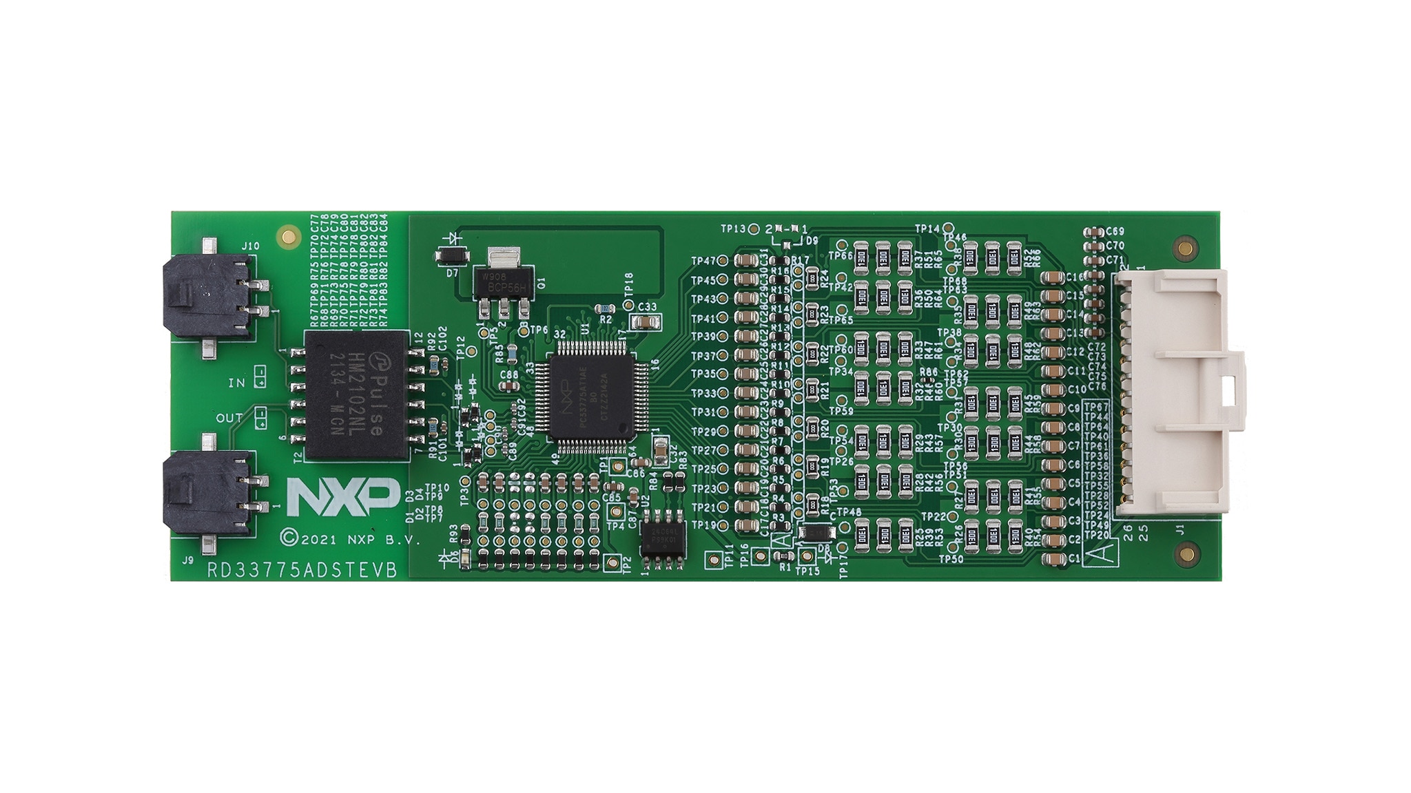
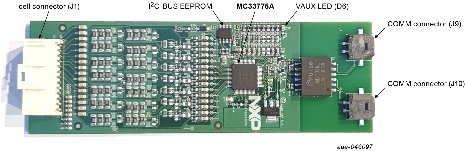
2.3 Board Components
Overview of the RD33775ADSTEVB board
3. Configure Hardware
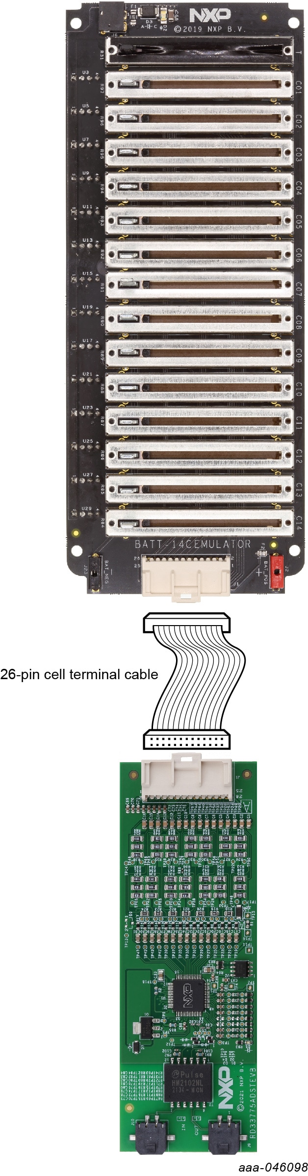
3.1 Battery Emulator Connection
A minimum of 4 cells and a maximum of 14 cells can be monitored. NXP provides a
14-cell battery emulator board, BATT-14CEMULATOR. This board provides an intuitive way to change the voltage across
any of the 14 cells of an emulated battery pack.
The board also provides one voltage output to emulate one external NTC. On the RD33775ADSTEVB, this one voltage is
connected to all four NTC inputs. The emulator board can be connected to the RD33775ADSTEVB connector J1 using the
provided supply cable; see Figure 1.
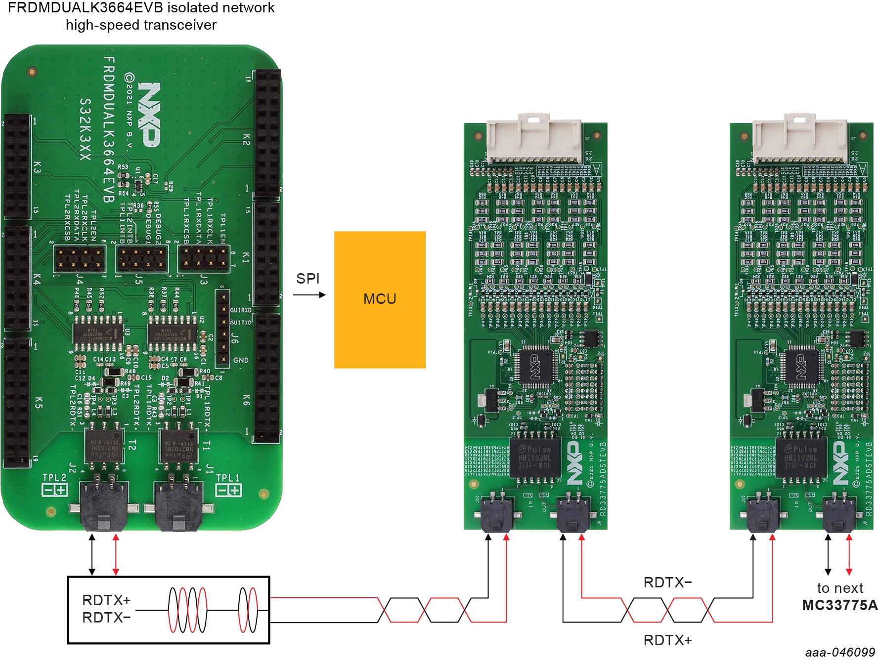
3.2 TPL Communication Connection
It is possible to connect the RD33775ADSTEVB to any MCU platform via SPI by using either the FRDMDUALK3664EVB or FRDM665SPIEVB gateway boards, translating SPI into TPL.
3.3 Using the FRDMDUALK3664EVB or FRDM665SPIEVB
In a high-voltage isolated application with a daisy chain configuration, up to 63 RD33775ADSTEVB boards may be connected.
The TPL connections use the COMM connectors (J9, J10).
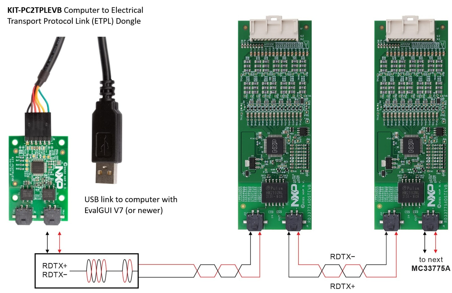
3.4 Using the KIT-PC2TPLEVB
To evaluate the MC33775 battery cell controller, it is possible to connect the RD33775ADSTEVB to a KIT-PC2TPLEVB to connect to a PC directly. This setup allows you to run the EvalGUI v7 (or newer) evaluation graphical interface available in the Software section of the RD33775ADSTEVB board page, to evaluate the device.
Design Resources
Board Information
Additional References
In addition to our MC33775, 14 Channel Li-Ion Battery Cell Controller IC ASIL D page, you may also want to visit:
Hardware pages:
Application pages: