Getting Started with the RDDRONE-BMS772 Reference Design
Contents of this document
-
Out of the Box
-
Get Hardware
-
Configure Hardware
Sign in to save your progress. Don't have an account? Create one.
Purchase your Smart Battery Management for Mobile Robotics 3-6 Cells
1. Out of the Box
The NXP analog product development boards provide an easy-to-use platform for evaluating NXP products. The boards support a range of analog, mixed-signal and power solutions. They incorporate monolithic integrated circuits and system-in-package devices that use proven high-volume technology. NXP products offer longer battery life, a smaller form factor, reduced component counts, lower cost and improved performance in powering state-of-the-art systems.
This page will guide you through the process of setting up and using the RDDRONE-BMS772 board.
1.1 Kit Contents and Packing List
The RDDRONE-BMS772 contents include:
- Assembled and tested RDDRONE-BMS772 in an anti-static bag
- CAN Bus Termination Resistor (DRONE-CAN-TERM)
- Unmounted cell balancing connectors for 3s, 4s and 6s
- 4-pin JST-GH to 4-pin JST-GH 300 mm cable
- Power input and power output connectors
- External thermistor with cable
- Small OLED display (soldered to the RDDRONE-BMS772 board)
- Quick start guide
1.2 Additional Hardware
In addition to the kit contents, the following hardware is necessary or beneficial when working with this kit.
- Battery pack (3s to 6s with cell balancing connector), with a range of 6.0 V to 26 V and a current limit of 60 A DC
-
Suitable charger for the battery
Note: The RDDRONE-BMS772 board allows to open the charge circuit when the battery is overcharging. Therefore, the charger does not need to have a BMS connector. - Soldering iron to configure the board
-
PEMicro universal multilink or SEGGER J-Link Mini debugger or other suitable debugger
Note: The DCD-LZ adapter and SEGGER J-Link Mini EDU are provided in the HoverGames Drone Kit (KIT-HGDRONEK66) and with the FMU (RDDRONEFMUK66).
2. Get Hardware
2.1 Board Description
The RDDRONE-BMS772 is a standalone BMS reference design suitable for mobile robotics such as drones and rovers, supporting 3 to 6 cells batteries. Other portable electronics and equipment, such as scooters, power tools, portable medical devices could also benefit from referencing this design. If higher cell counts are required, this could be redesigned to daisy chain multiple BCC chips or switch to a larger cell count BCC such as MC33771B.
The device performs ADC conversion on the differential cell voltages and currents. It is capable of accurate battery charge coulomb counting and battery temperature measurements. Additionally, it communicates with a Flight Management Unit (FMU) through UAVCAN and/or an SMBus.
2.2 RDDRONE-BMS772 Features
The RDDRONE-BMS772 integrates the following functions and features:
- Supports battery from 3s to 6s, with stack voltage ranging from 6.0 V to 26 V
- Supports ambient temperature range from −20 °C to 60 °C
- Measures battery stack and cell voltages with an accuracy of ± 5.0 mV, battery charge or discharge current up to 200 A peak and 90 A DC
- Active cell balancing during charging
- Offers a deep sleep mode (for transportation and storage) with low leakage current, as well as an automatic sleep mode with low current consumption on the battery
- Allows authentication of the battery
- Allows diagnostics to verify the safe operation of the battery
- Allows CAN, I²C and NFC communication
- Implements SWD and JTAG debugging interfaces, works with standard J-Link and other debuggers
- Implements DCD-LZ combined debug console interface for use with PX4 DroneCode and HoverGames platforms
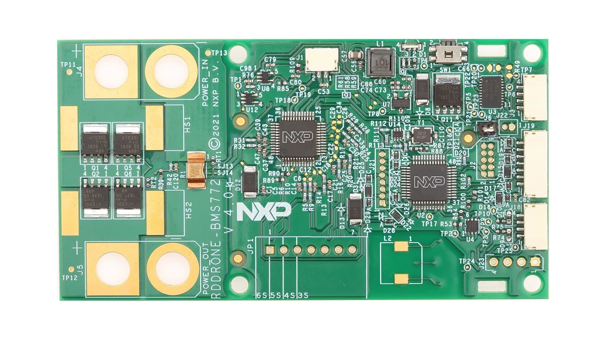
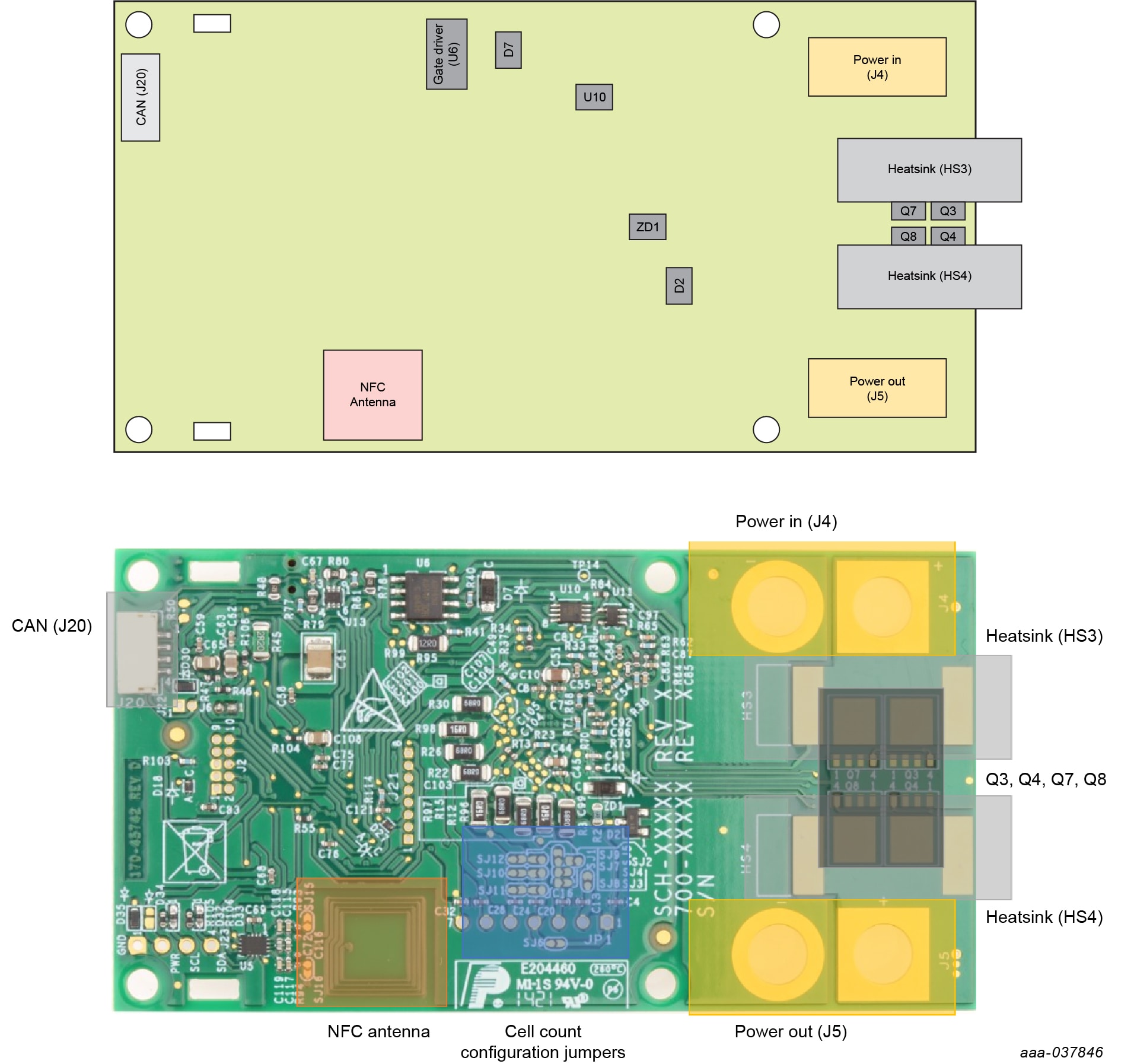
2.3 Board Components
Overview of the RDDRONE-BMS772 board
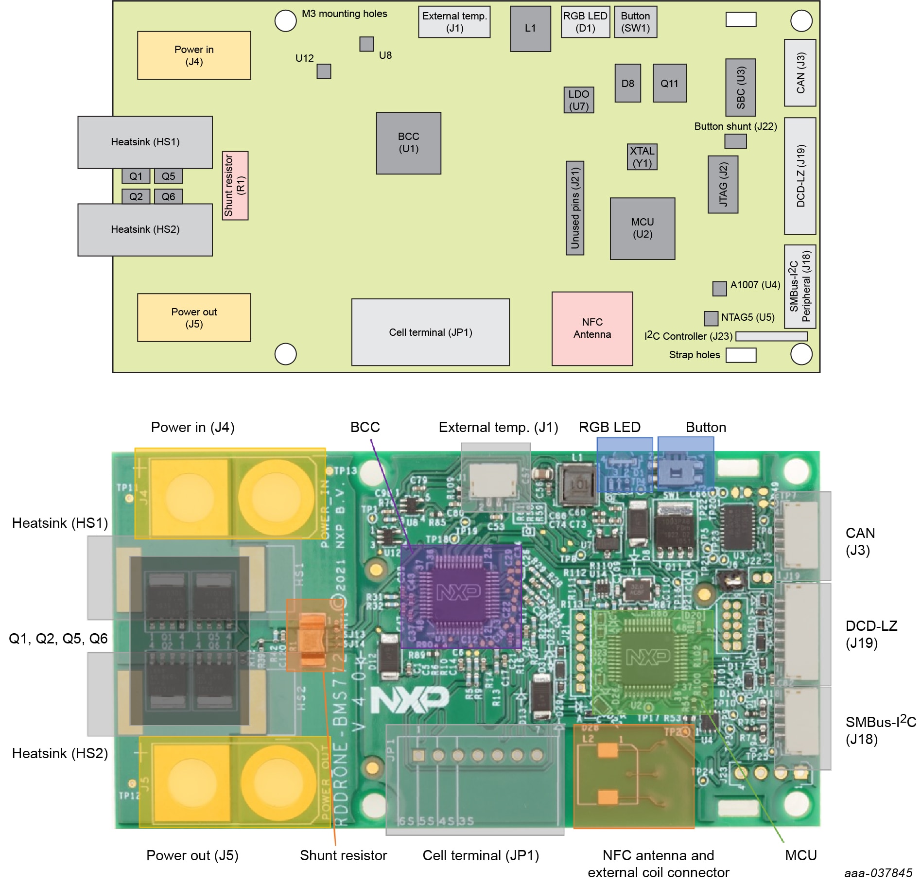
The main featured devices are listed in the following table:
Table 1. Featured devices
| Label | Description | Reference |
|---|---|---|
| U1 | Battery Cell Controller (BCC) | MC33772BSP1AE |
| U2 | Micro-Controller Unit (MCU) | FS32K144HAT0MLFT |
| U3 | System Basis Chip (SBC) | UJA1169TK/F/3 |
| U4 | Authentication | A1007 |
| U5 | Near-Field Communication (NFC) | NTA53321G10FHK |
3. Configure Hardware
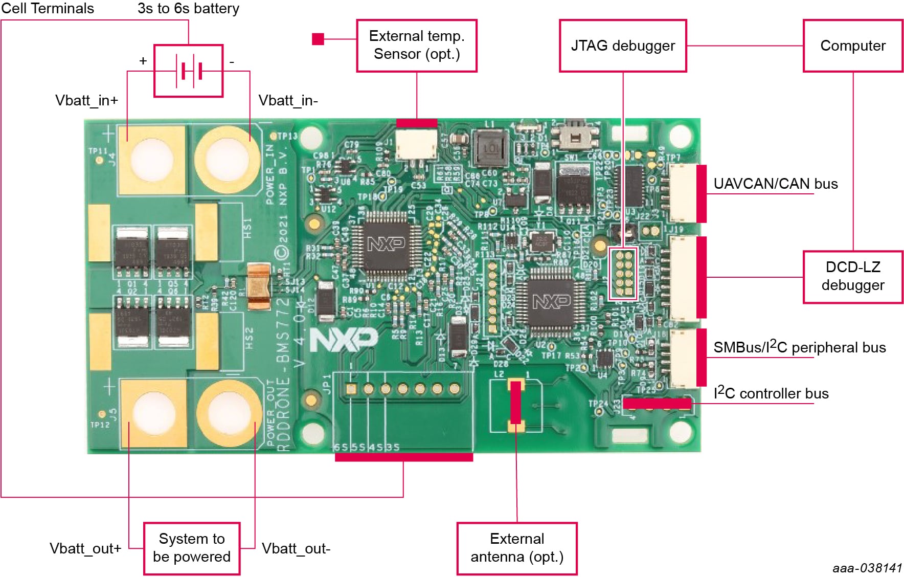
Before first start-up, make sure that the board is configured properly:
- Solder your power in and power out connectors or wires on the
J4andJ5footprints - Solder the correct cell terminal connector at the
JP1location. Ensure it is correctly positioned and aligned - Configure the board for your application by soldering the corresponding SJxx connectors
- Configure the board with additional and/or optional components to fit the application requirements
- Once the board is configured properly, connect the board. To power On the RDDRONE-BMS772 board, connect the battery to the power input connector
(J4)first, and then the cell terminal connector(JP1). This protects the boards form internal damage due to hot plugging.
3.1 Ready to Use
Start embedded application development.
Design Resources
Board Documents
Additional References
In addition to our MC33772B: 6-Channel Li-ion Battery Cell Controller IC page, you may also want to visit:
Product pages:
- S32K1 microcontrollers for General Purpose
- NTAG®5 boost: NFC Forum-compliant I²C bridge for tiny devices
- MC33771B: 14-Channel Li-ion Battery Cell Controller IC
Application pages:
Hardware pages:
Software pages:
Support
Forums
Connect with other engineers and get expert advice on designing with the RDDRONE-BMS772 Reference Design on one of our community sites.