S32K344 EVB Quick Start Guides
Contents of this document
-
Out of the Box
-
Get Software
-
Plug It In
-
Build, Run
Sign in to save your progress. Don't have an account? Create one.
Purchase your S32K344-WB Evaluation Board for Automotive General Purpose
1. Out of the Box
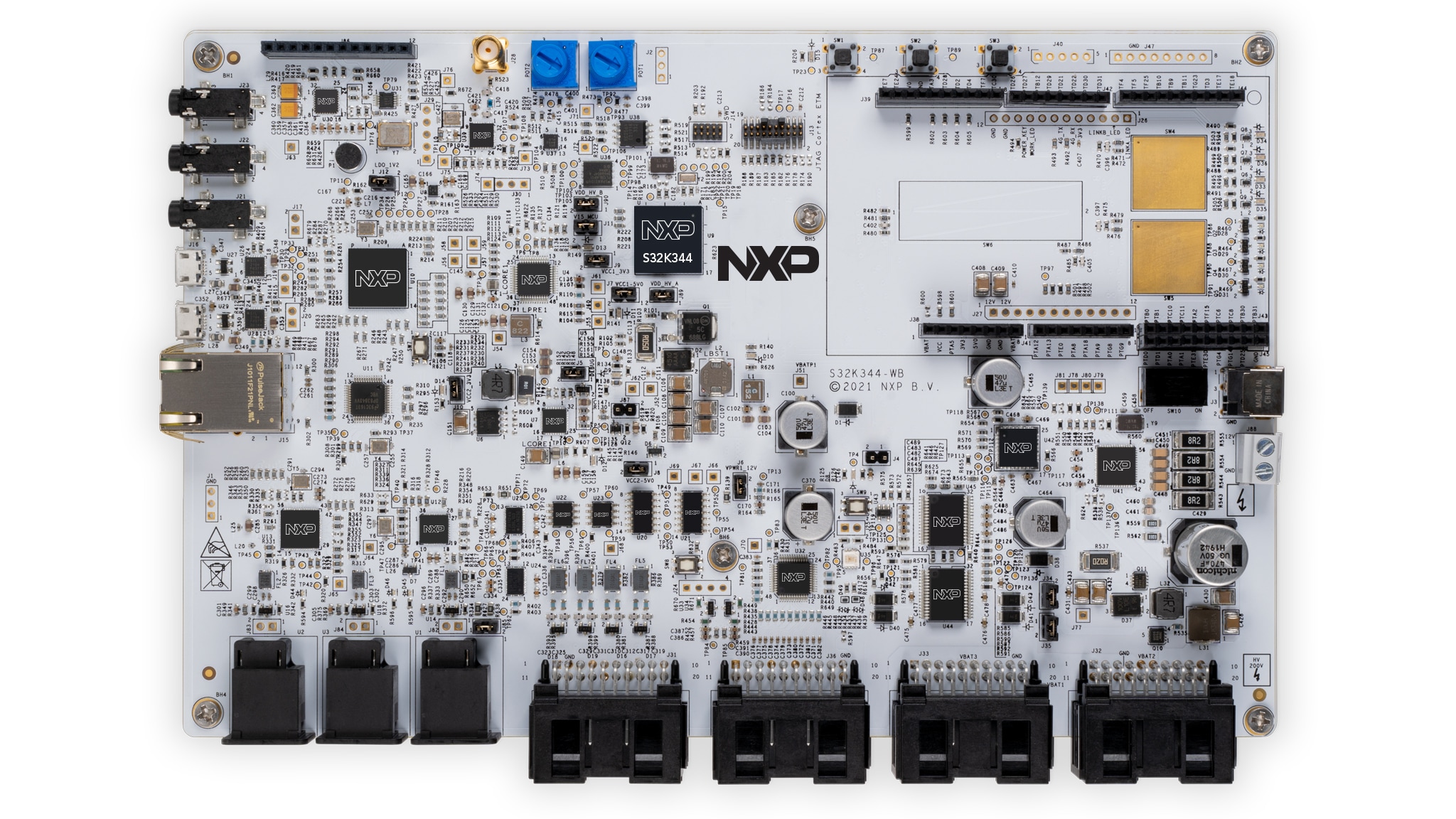
1.1 Get to Know the S32K344-WB Evaluation Board
Let’s start using the S32K3-WB evaluation board.
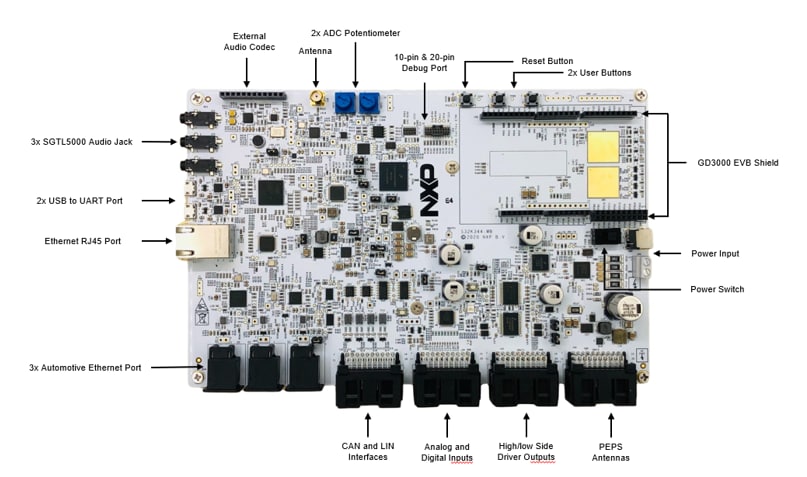
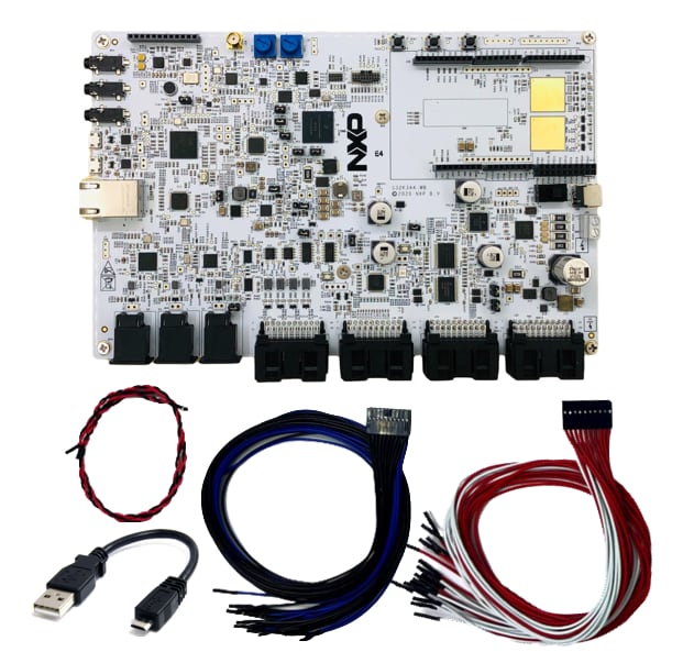
Discover what is inside your box of your S32K344-WB evaluation board.

2. Get Software
You can watch the video or follow the below step-by-step guide to set up your S32K344-WB Evaluation Board:
2.1 Get the Integrated Development Environment (IDE)
Download and install S32 Design Studio IDE for S32 Platform
Download S32 DESIGN STUDIO IDE
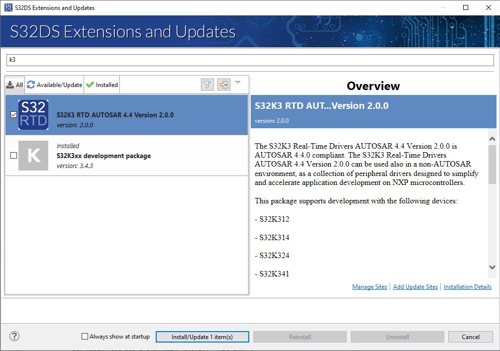
2.2 Install the S32K3xx Development Package
- Go to Help
- S32DS Extensions and Updates from the top menu to open the S32DS Extensions and Updates
- Navigate to the S32K3xx development package and install it
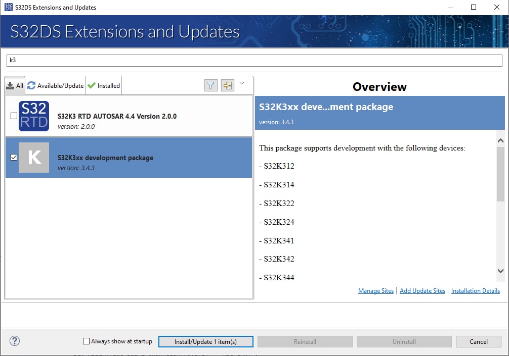
Continue with the installation of the S32K3 Real-Time Drivers:
3. Plug It In
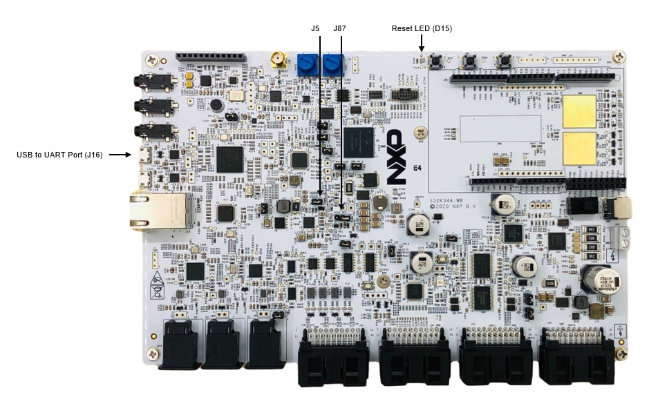
3.1 Set Up Jumpers in the S32K344-WB Evaluation Board
3.2 Connect Power Supply
Ensure that SW10 is in OFF position, connect the 12 V power supply adaptor and then switch SW10 to the ON position. If you see the reset LED(D15) blinking, it's possible that the FS26 is in normal mode and FS26 triggered the reset due to no watchdog feeding from the MCU. In such a case, switch SW10 OFF and ON again.
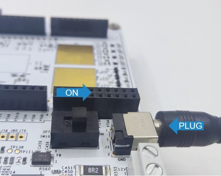
The successful power-on is signalized by several power-domain LEDs. For more details and LED positions please read the chapter 5 in the S32K344 White Board HW User Manual.
4. Build, Run
4.1 Build, Run
The software contains rich example set for both High Level Driver (HLD) and Low Level Drivers (LLD). The HLD example set is based on S32K3 RTD version 1.0.0, while LLD example set is based on S32K3 RTD version 2.0.0. The next instructions are for LLD example set.
Download the s32k3_wb_self_test project in the software package S32K344_Whiteboard_Example(LLD)_RTM_1.0.0.zip. Import to S32DS, compile and upload the firmware to the board. Connect the board(J16) to the PC with the MicroUSB cable. Set the UART assistant parameters on the PC as 115200, 8, None, 1. You should be able to see below printing information.
***************************************************************
********************Clock init done****************************
Reset source DES=0x00000000, FES=0x000000001.
Reset count FREC=0.
Base task init OK.
FS26 basic init done.
FS26 all registers read OK.
Reg_flag=0x0101.
Regulator flag set.
FS26 WDG refresh OK.
TJA11xx device 1 is TJA1145.
TJA11xx device 1 initialization OK.
TJA11xx device 1 entered normal mode.
TJAIIxx device 2 is TJA1145.
TJAIIxx device 2 initialization OK.
TJA11xx device 2 entered normal mode.
CDI030 initialization OK.
HB2001 initialization OK.
LPUART and TJA1124 are initialized!
SJA1124 Detected. Read SJA1124 ID = 25.
SJA1124 initialization OK!
MC33879 initialization OK.
MB85RC256 FRAM read write test OK.
QSPI Flash ProgramVerify test OK.
NJJ29C2 SPI Initial read OK.
NCK2910 SPI Communication OK.
SJA1105P initialization OK.
Read SJA1105P 10: 0xAE00030E.
S32K3 GMAC initialization OK.
Eth Phy TJA1101 and TJA1102 init OK.
CS2100 initialized, and init OK!
SGTL5000 initialized, and init OK!
All self-test results OK.
For more details about importing and building the project read the chapter 2 in the S32K344 Whiteboard SW(LLD) QuickStartGuide. For more details about downloading code into MCU and debugging please read the chapter 7 in the S32K344 Whiteboard SW(HLD) UserGuide.
RTD Examples
RTD Examples
Kickstart your RTD journey with these handy examples. We've rounded up some of the most common use cases to get you inspired and moving forward.
Users can copy the path directly into their window once the RTD is downloaded.
ADC
C:\NXP\S32DS.3.6.1\S32DS\software\PlatformSDK_S32K3\RTD\Adc_TS_T40D34M30I0R0\examples\S32DS\S32K3XX\Adc_example_S32K344 ADC SAR BCTU IP
C:\NXP\S32DS.3.6.1\S32DS\software\PlatformSDK_S32K3\RTD\Adc_TS_T40D34M30I0R0\examples\S32DS\S32K3XX\Adc_Sar_Bctu_Ip_example_S32K344 CAN
C:\NXP\S32DS.3.6.1\S32DS\software\PlatformSDK_S32K3\RTD\Can_43_FLEXCAN_TS_T40D34M30I0R0\examples\S32DS\S32K3XX\Can_Example_S32K344 FLEXCAN IP
C:\NXP\S32DS.3.6.1\S32DS\software\PlatformSDK_S32K3\RTD\Can_43_FLEXCAN_TS_T40D34M30I0R0\examples\S32DS\S32K3XX\FlexCAN_Ip_Example_S32K344 CRC
C:\NXP\S32DS.3.6.1\S32DS\software\PlatformSDK_S32K3\RTD\Crc_TS_T40D34M30I0R0\examples\S32DS\S32K3XX\Crc_Example_S32K344 CRC IP
C:\NXP\S32DS.3.6.1\S32DS\software\PlatformSDK_S32K3\RTD\Crc_TS_T40D34M30I0R0\examples\S32DS\S32K3XX\Crc_Ip_Example_S32K344 CRYPTO CMAC CTR KEY GEN
C:\NXP\S32DS.3.6.1\S32DS\software\PlatformSDK_S32K3\RTD\Crypto_TS_T40D34M30I0R0\examples\S32DS\S32K3XX\Crypto_CmacCtr_KeyGenBD_S32K344 CRYPTO SYMMETRIC PRIMITIVES
C:\NXP\S32DS.3.6.1\S32DS\software\PlatformSDK_S32K3\RTD\Crypto_TS_T40D34M30I0R0\examples\S32DS\S32K3XX\Crypto_SymmetricPrimitives_S32K344 HSE IP
C:\NXP\S32DS.3.6.1\S32DS\software\PlatformSDK_S32K3\RTD\Crypto_TS_T40D34M30I0R0\examples\S32DS\S32K3XX\Hse_Ip_AesEncAsyncIrq_S32K344 DIO
C:\NXP\S32DS.3.6.1\S32DS\software\PlatformSDK_S32K3\RTD\Dio_TS_T40D34M30I0R0\examples\S32DS\S32K3XX\Dio_Example_S32K344 SIUL2 DIO IP
C:\NXP\S32DS.3.6.1\S32DS\software\PlatformSDK_S32K3\RTD\Dio_TS_T40D34M30I0R0\examples\S32DS\S32K3XX\Siul2_Dio_Ip_Example_S32K344 ETH
C:\NXP\S32DS.3.6.1\S32DS\software\PlatformSDK_S32K3\RTD\Eth_43_GMAC_TS_T40D34M30I0R0\examples\S32DS\S32K3XX\Eth_InternalLoopback_S32K344 GMAC IP
C:\NXP\S32DS.3.6.1\S32DS\software\PlatformSDK_S32K3\RTD\Eth_43_GMAC_TS_T40D34M30I0R0\examples\S32DS\S32K3XX\Gmac_Ip_InternalLoopback_S32K344 FEE
C:\NXP\S32DS.3.6.1\S32DS\software\PlatformSDK_S32K3\RTD\Fee_TS_T40D34M30I0R0\examples\S32DS\S32K3XX\Fee_Example_S32K344 GPT
C:\NXP\S32DS.3.6.1\S32DS\software\PlatformSDK_S32K3\RTD\Gpt_TS_T40D34M30I0R0\examples\S32DS\S32K3XX\Gpt_Example_S32K344 PIT GPT IP
C:\NXP\S32DS.3.6.1\S32DS\software\PlatformSDK_S32K3\RTD\Gpt_TS_T40D34M30I0R0\examples\S32DS\S32K3XX\Pit_Gpt_Ip_Example_S32K344 I²C
C:\NXP\S32DS.3.6.1\S32DS\software\PlatformSDK_S32K3\RTD\I2c_TS_T40D34M30I0R0\examples\S32DS\S32K3XX\I2c_HLD_FLEXIO_Transfer_S32K344 I²C (Q172)
C:\NXP\S32DS.3.6.1\S32DS\software\PlatformSDK_S32K3\RTD\I2c_TS_T40D34M30I0R0\examples\S32DS\S32K3XX\I2c_HLD_FLEXIO_Transfer_S32K344_Q172 I²C IP
C:\NXP\S32DS.3.6.1\S32DS\software\PlatformSDK_S32K3\RTD\I2c_TS_T40D34M30I0R0\examples\S32DS\S32K3XX\I2c_IP_FLEXIO_Transfer_S32K344 I²C IP (Q172)
C:\NXP\S32DS.3.6.1\S32DS\software\PlatformSDK_S32K3\RTD\I2c_TS_T40D34M30I0R0\examples\S32DS\S32K3XX\I2c_IP_FLEXIO_Transfer_S32K344_Q172 I²S
C:\NXP\S32DS.3.6.1\S32DS\software\PlatformSDK_S32K3\RTD\I2s_TS_T40D34M30I0R0\examples\S32DS\S32K3XX\I2s_Example_Flexio_Master_Tx_Sai_Slave_Rx_S32K344 EMIOS ICU IP
C:\NXP\S32DS.3.6.1\S32DS\software\PlatformSDK_S32K3\RTD\Icu_TS_T40D34M30I0R0\examples\S32DS\S32K3XX\Emios_Icu_Ip_BlinkLed_S32K344 ICU
C:\NXP\S32DS.3.6.1\S32DS\software\PlatformSDK_S32K3\RTD\Icu_TS_T40D34M30I0R0\examples\S32DS\S32K3XX\Icu_BlinkLed_ASR_Emios_S32K344 LIN IP
C:\NXP\S32DS.3.6.1\S32DS\software\PlatformSDK_S32K3\RTD\Lin_43_LPUART_FLEXIO_TS_T40D34M30I0R0\examples\S32DS\S32K3XX\Lin_Ip_FrameTransfer_S32K344 LIN Leader
C:\NXP\S32DS.3.6.1\S32DS\software\PlatformSDK_S32K3\RTD\Lin_43_LPUART_FLEXIO_TS_T40D34M30I0R0\examples\S32DS\S32K3XX\Lin_MasterFrameTransfer_S32K344 DMA IP
C:\NXP\S32DS.3.6.1\S32DS\software\PlatformSDK_S32K3\RTD\Mcl_TS_T40D34M30I0R0\examples\S32DS\S32K3XX\Dma_Ip_DmaTransfer_S32K344 LCU IP
C:\NXP\S32DS.3.6.1\S32DS\software\PlatformSDK_S32K3\RTD\Mcl_TS_T40D34M30I0R0\examples\S32DS\S32K3XX\Lcu_Ip_LcuControlMotor_S32K344 MCL
C:\NXP\S32DS.3.6.1\S32DS\software\PlatformSDK_S32K3\RTD\Mcl_TS_T40D34M30I0R0\examples\S32DS\S32K3XX\Mcl_DmaTransfer_S32K344 CLOCK IP
C:\NXP\S32DS.3.6.1\S32DS\software\PlatformSDK_S32K3\RTD\Mcu_TS_T40D34M30I0R0\examples\S32DS\S32K3XX\Clock_Ip_Example_S32K344 MCU
C:\NXP\S32DS.3.6.1\S32DS\software\PlatformSDK_S32K3\RTD\Mcu_TS_T40D34M30I0R0\examples\S32DS\S32K3XX\Mcu_Example_S32K344 POWER IP
C:\NXP\S32DS.3.6.1\S32DS\software\PlatformSDK_S32K3\RTD\Mcu_TS_T40D34M30I0R0\examples\S32DS\S32K3XX\Power_Ip_Example_S32K344 MEM
C:\NXP\S32DS.3.6.1\S32DS\software\PlatformSDK_S32K3\RTD\Mem_43_ExFls_TS_T40D34M30I0R0\examples\S32DS\S32K3XX\Mem_43_ExFls_Example_S32K344 QSPI IP
C:\NXP\S32DS.3.6.1\S32DS\software\PlatformSDK_S32K3\RTD\Mem_43_ExFls_TS_T40D34M30I0R0\examples\S32DS\S32K3XX\Qspi_Ip_Example_S32K344 C40 IP
C:\NXP\S32DS.3.6.1\S32DS\software\PlatformSDK_S32K3\RTD\Mem_43_InFls_TS_T40D34M30I0R0\examples\S32DS\S32K3XX\C40_Ip_Example_S32K344 MEM INFLS
C:\NXP\S32DS.3.6.1\S32DS\software\PlatformSDK_S32K3\RTD\Mem_43_InFls_TS_T40D34M30I0R0\examples\S32DS\S32K3XX\Mem_InFls_Example_S32K344 MEM ACC
C:\NXP\S32DS.3.6.1\S32DS\software\PlatformSDK_S32K3\RTD\MemAcc_TS_T40D34M30I0R0\examples\S32DS\S32K3XX\MemAcc_Example_S32K344 EMIOS OCU IP
C:\NXP\S32DS.3.6.1\S32DS\software\PlatformSDK_S32K3\RTD\Ocu_TS_T40D34M30I0R0\examples\S32DS\S32K3XX\eMios_Ocu_Ip_Example_S32K344 OCU
C:\NXP\S32DS.3.6.1\S32DS\software\PlatformSDK_S32K3\RTD\Ocu_TS_T40D34M30I0R0\examples\S32DS\S32K3XX\Ocu_Example_S32K344 PLATFORM MPU HLD
C:\NXP\S32DS.3.6.1\S32DS\software\PlatformSDK_S32K3\RTD\Platform_TS_T40D34M30I0R0\examples\S32DS\S32K3XX\Platform_MPU_HLD_Example_S32K344 PLATFORM MPU IP
C:\NXP\S32DS.3.6.1\S32DS\software\PlatformSDK_S32K3\RTD\Platform_TS_T40D34M30I0R0\examples\S32DS\S32K3XX\Platform_MPU_IP_Example_S32K344 PORT
C:\NXP\S32DS.3.6.1\S32DS\software\PlatformSDK_S32K3\RTD\Port_TS_T40D34M30I0R0\examples\S32DS\S32K3XX\Port_Example_S32K344 SIUL2 PORT IP
C:\NXP\S32DS.3.6.1\S32DS\software\PlatformSDK_S32K3\RTD\Port_TS_T40D34M30I0R0\examples\S32DS\S32K3XX\Siul2_Port_Ip_Example_S32K344 EMIOS PWM IP
C:\NXP\S32DS.3.6.1\S32DS\software\PlatformSDK_S32K3\RTD\Pwm_TS_T40D34M30I0R0\examples\S32DS\S32K3XX\Emios_Pwm_Ip_Example_S32K344 FLEXIO PWM IP
C:\NXP\S32DS.3.6.1\S32DS\software\PlatformSDK_S32K3\RTD\Pwm_TS_T40D34M30I0R0\examples\S32DS\S32K3XX\Flexio_Pwm_Ip_Example_S32K344 PWM
C:\NXP\S32DS.3.6.1\S32DS\software\PlatformSDK_S32K3\RTD\Pwm_TS_T40D34M30I0R0\examples\S32DS\S32K3XX\Pwm_example_S32K344 RM DMAMUX
C:\NXP\S32DS.3.6.1\S32DS\software\PlatformSDK_S32K3\RTD\Rm_TS_T40D34M30I0R0\examples\S32DS\S32K3XX\Rm_DMAMUX_Example_S32K344 RM
C:\NXP\S32DS.3.6.1\S32DS\software\PlatformSDK_S32K3\RTD\Rm_TS_T40D34M30I0R0\examples\S32DS\S32K3XX\Rm_Example_S32K344 RM MSCM
C:\NXP\S32DS.3.6.1\S32DS\software\PlatformSDK_S32K3\RTD\Rm_TS_T40D34M30I0R0\examples\S32DS\S32K3XX\Rm_Mscm_Example_S32K344 RM VIRT WRAP
C:\NXP\S32DS.3.6.1\S32DS\software\PlatformSDK_S32K3\RTD\Rm_TS_T40D34M30I0R0\examples\S32DS\S32K3XX\Rm_Virt_Wrap_Example_S32K344 RM XBIC
C:\NXP\S32DS.3.6.1\S32DS\software\PlatformSDK_S32K3\RTD\Rm_TS_T40D34M30I0R0\examples\S32DS\S32K3XX\Rm_Xbic_Example_S32K344 SENT RECEIVER
C:\NXP\S32DS.3.6.1\S32DS\software\PlatformSDK_S32K3\RTD\Sent_TS_T40D34M30I0R0\examples\S32DS\S32K3XX\Sent_Receiver_S32K344 LPSPI FLEX IP
C:\NXP\S32DS.3.6.1\S32DS\software\PlatformSDK_S32K3\RTD\Spi_TS_T40D34M30I0R0\examples\S32DS\S32K3XX\Lpspi_Flexio_Ip_Transfer_S32K344 LPSPI IP
C:\NXP\S32DS.3.6.1\S32DS\software\PlatformSDK_S32K3\RTD\Spi_TS_T40D34M30I0R0\examples\S32DS\S32K3XX\Lpspi_Ip_HalfDuplexTransfer_S32K344 SPI HALF DUPLEX
C:\NXP\S32DS.3.6.1\S32DS\software\PlatformSDK_S32K3\RTD\Spi_TS_T40D34M30I0R0\examples\S32DS\S32K3XX\Spi_HalfDuplexTransfer_S32K344 SPI
C:\NXP\S32DS.3.6.1\S32DS\software\PlatformSDK_S32K3\RTD\Spi_TS_T40D34M30I0R0\examples\S32DS\S32K3XX\Spi_Transfer_S32K344 LPUART FLEXIO UART IP
C:\NXP\S32DS.3.6.1\S32DS\software\PlatformSDK_S32K3\RTD\Uart_TS_T40D34M30I0R0\examples\S32DS\S32K3XX\LpuartFlexio_Uart_Ip_Example_S32K344 UART
C:\NXP\S32DS.3.6.1\S32DS\software\PlatformSDK_S32K3\RTD\Uart_TS_T40D34M30I0R0\examples\S32DS\S32K3XX\Uart_Example_S32K344 SWT IP
C:\NXP\S32DS.3.6.1\S32DS\software\PlatformSDK_S32K3\RTD\Wdg_TS_T40D34M30I0R0\examples\S32DS\S32K3XX\Swt_Ip_Example_S32K344 WDOG
C:\NXP\S32DS.3.6.1\S32DS\software\PlatformSDK_S32K3\RTD\Wdg_TS_T40D34M30I0R0\examples\S32DS\S32K3XX\Wdg_Example_S32K344 Design Resources
Board Information
Chip Documents
Software
- Automotive Software Package Manager
- How To Use the Automotive Software Package Manager
- S32K3 Standard Software Package
- S32K3 Reference Software Package
- S32 Design Studio IDE
- Real-Time Drivers (RTD)
- S32K Power Estimation Tool (PET)
- Model-Based Design Toolbox (MBDT)
- Structural Core Self-Test (SCST) Library
- FreeMASTER Run-Time Debugging Tool
- Inter-Platform Communication Framework (IPCF)
- Automotive Math and Motor Control Library (AMMCLib)
- S32 Safety Software Framework (SAF) and Safety Peripheral Drivers (SPD)
Support
Training
Forums
Connect with other engineers and get expert advice on designing with the S32K344-WB evaluation board using our community sites