Getting Started with the SLN-VIZNAS-IOT
Contents of this document
-
Plug It In
-
Get Software
-
Build, Run
Sign in to save your progress. Don't have an account? Create one.
Purchase your NXP EdgeReady MCU-Based Solution for Face Recognition with Liveness Detection
1. Plug It In
Welcome to the SLN-VIZNAS-IOT Getting Started Guide, In this document, we will discuss how to get up and running with your kit, how to grab a hold of the hardware and software files to begin developing with the kit yourself, and resources where you can learn more about the topics covered in this guide.
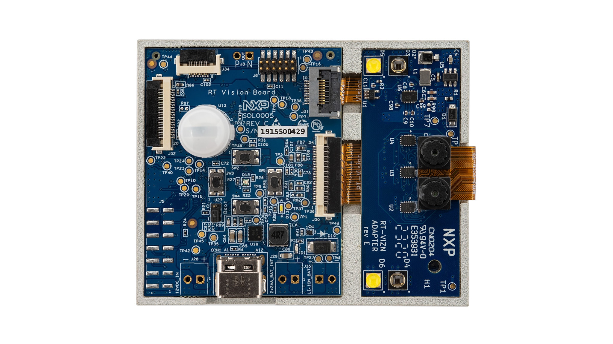
1.1 Unboxing
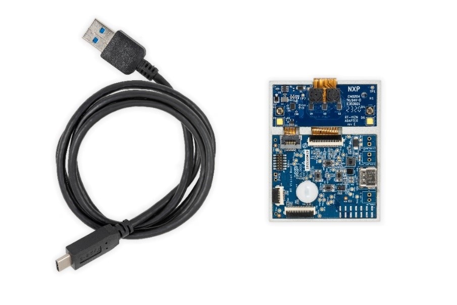
Please check your kit for damage or marks, and, if seen, please contact your NXP representative.
1.2 Power On
To get started, take the USB-C cable provided inside the kit and plug the USB-A end into your computer and the USB-C end into your kit.
We recommend using a USB-A port which can support up to 1 A of current at 5 V. This is necessary for configurations utilizing the audio amplifier and other optional hardware on the kit.
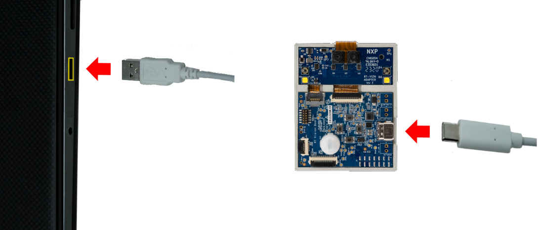
Once connected, a green LED (D1) will light up to indicate the kit is receiving
power.
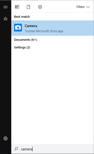
1.3 Access the Camera
With the kit powered on and connected to your computer, the SLN-VIZNAS-IOT kit will automatically enumerate as both a serial device and USB camera device. To access the kit’s camera, open Camera if using Windows, or Cheese, if using Ubuntu. In this guide, we’ll be using Windows and the Windows camera app.
After opening the camera app, video coming directly from the kit will be shown in the camera window.
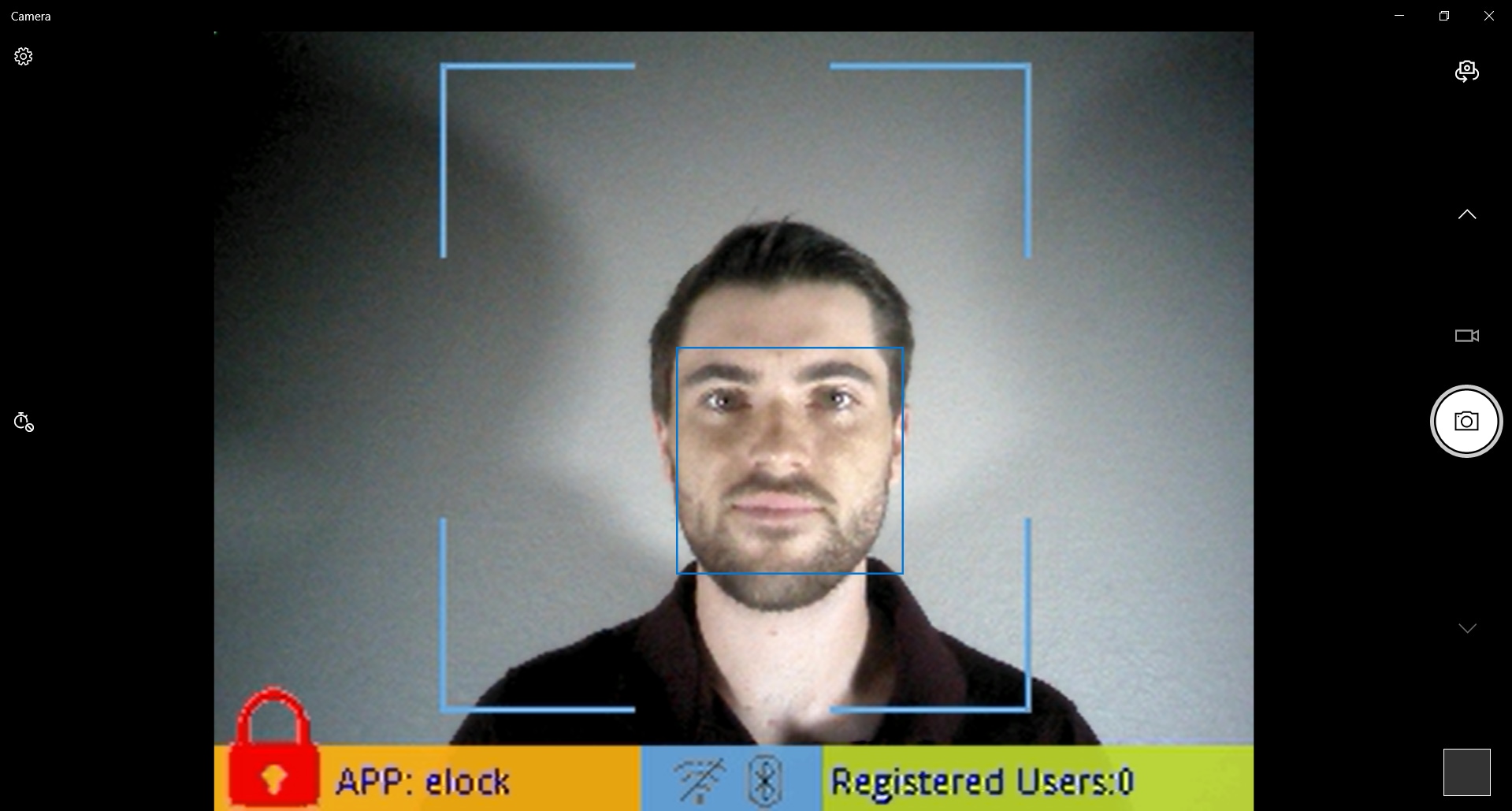
If you have multiple cameras connected to your computer, you may need to change which camera is being shown. In the Windows Camera app, this can be done by using the “Change Camera” button located in the top right-hand corner of the app.
1.4 Register Face
To make use of the recognition feature of the SLN-VIZNAS-IOT, a face must be registered in
the kit’s
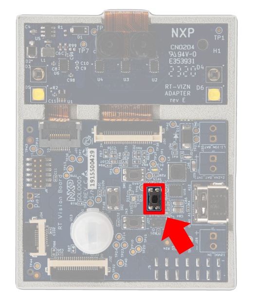
local face database. To begin registering a new face, press the Manual
Registration
button on the kit
(SW4).
Once pressed, a message indicating registration is taking place will pop up at the top of the screen.
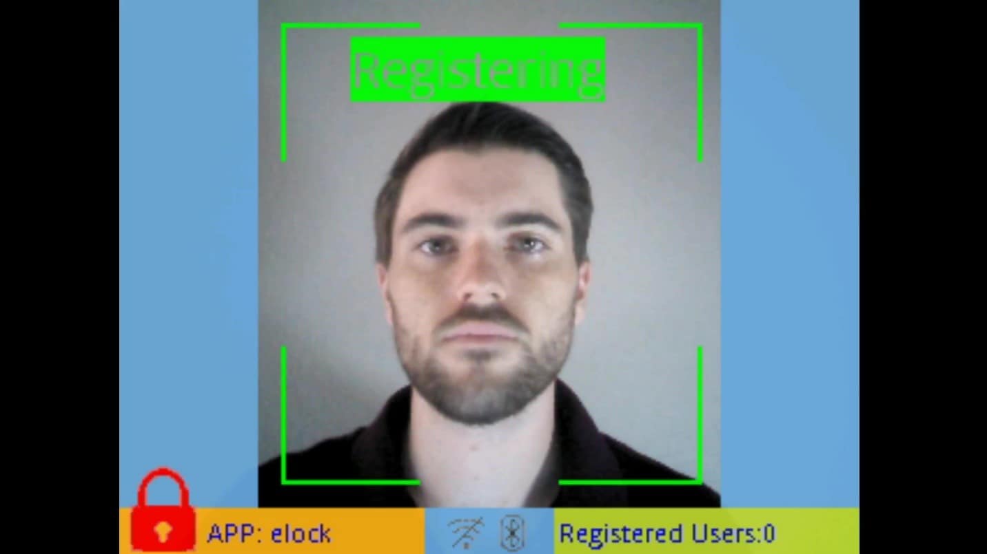
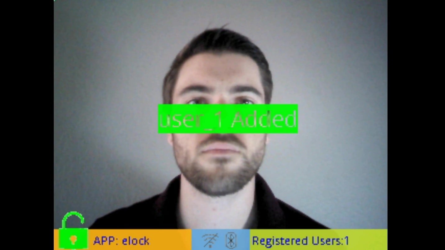
To register your face, stare straight-on at the camera and wait for the box around your face to turn from red to green. When registering a face via the buttons on the kit, a generic username will be assigned to the newly registered face.
Should your face fail to register properly, either due to the registration being canceled or timing out, a message like the following will be displayed:
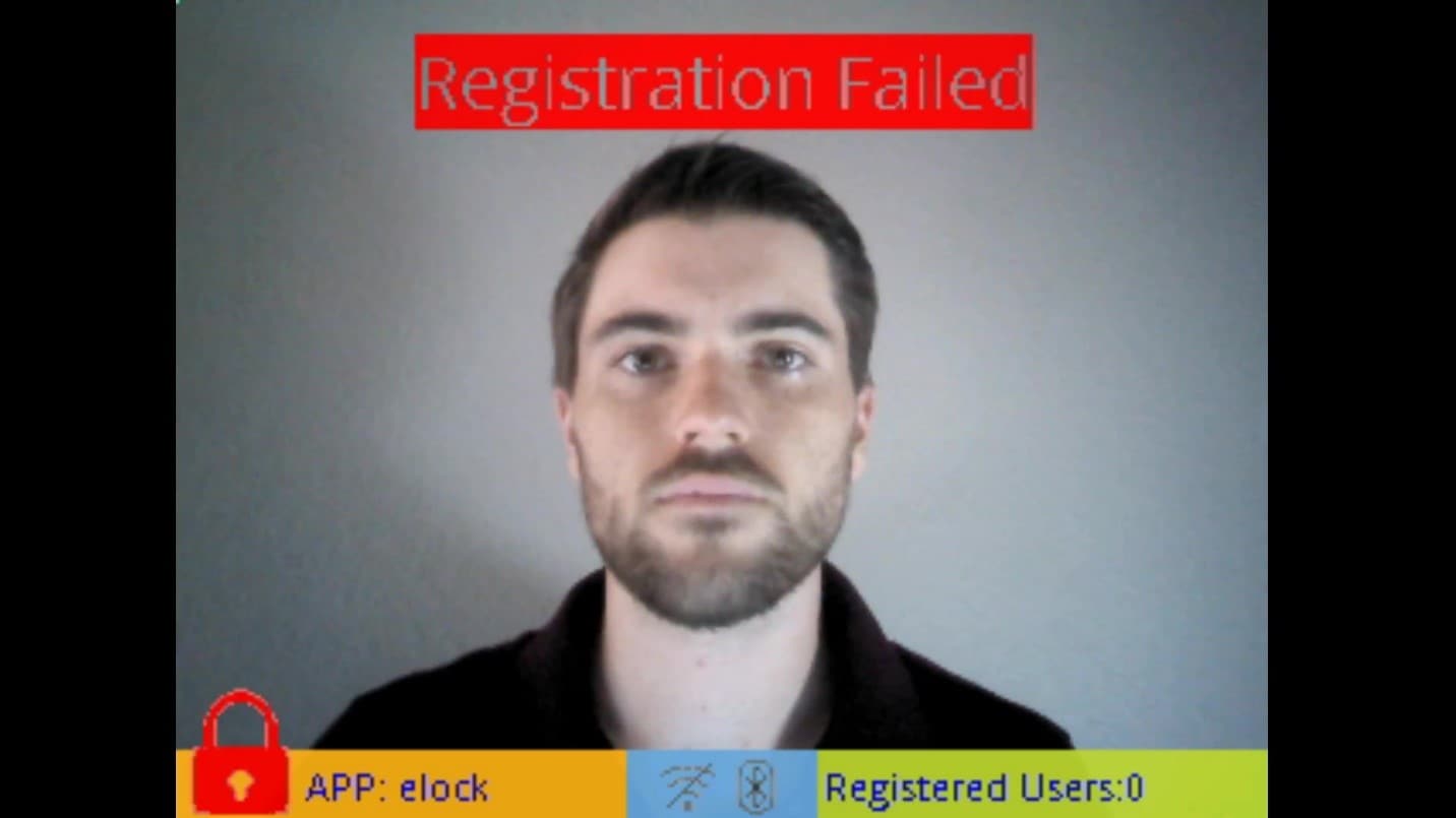
To retry, simply press the manual registration button again.
Once registered, recognition of your face will prompt a “Welcome Home” message, indicating the kit has detected a recognized face.
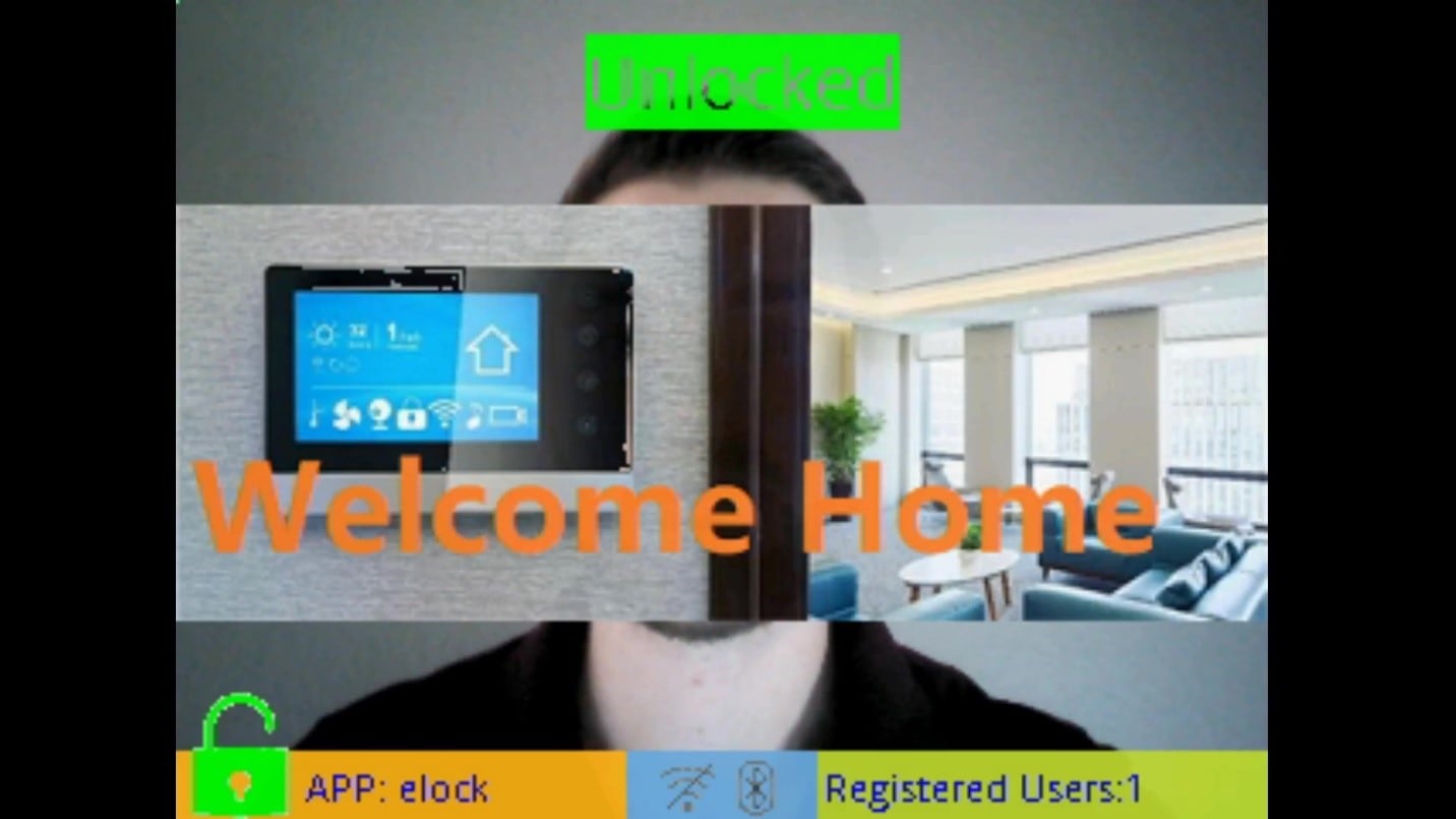
Your face will continue to be recognized so long as the system is running. By default, however, faces will be erased upon reset and must be explicitly saved into flash using the “save” CLI command if you want those faces to continue being recognized after a reset. Using CLI commands and the kit’s built-in shell will be discussed in a later section.
1.5 Liveness Detection and Anti-Spoofing
The SLN-VIZNAS-IOT comes with Liveness Detection and Anti-Spoofing turned ON by default, meaning that the system can discern between your actual face and a print-out/phone display picture of your face.

By requiring a user’s actual face to be able to unlock the system, as opposed to a simple picture of the user’s face, this feature helps to protect against some of the most common face recognition “spoof” attacks wherein a malicious actor will use a picture of someone to gain access to their face-protected materials.
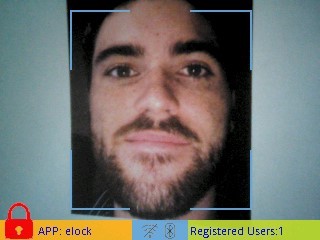
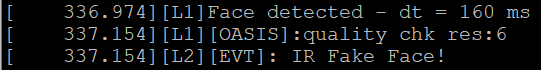
As shown in the screenshots above, using neither a phone display nor a printed picture of a face triggers the “Welcome Home” message. In fact, if we enable the verbose mode discussed in a later section, while attempting to recognize the above printed picture, we can see that the inference engine detects a face, but recognizes that the image captured by the IR camera is a “fake”/”spoofed” face.
1.6 Connect to Serial CLI
This step requires that you have installed a serial terminal emulator like PuTTY or Tera Term.
Not sure how to use a terminal application? Try one of these tutorials: Tera Term Tutorial, PuTTY Tutorial.
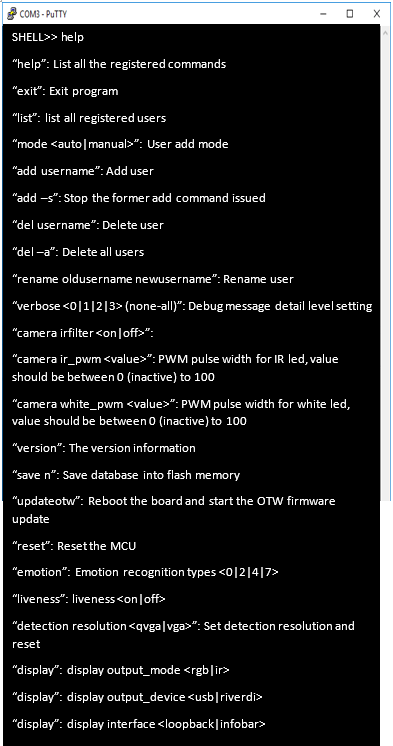
After connecting to the kit’s serial interface, you will encounter a blank terminal screen that echoes any characters that you type. Use the “help” command to display a list of all the available serial commands and their usage. We will be discussing a few of these commands in the upcoming sections.
| Command | Arguments | Description |
|---|---|---|
|
help |
- |
Display a list of all available serial commands along with a brief description of their function |
|
exit |
- |
Exit program; closes serial terminal until reset |
|
list |
- |
List all registered users |
|
add |
USERNAME |
Add new user with specified username |
|
add |
-s |
Stops attempting to add a new user |
|
del |
USERNAME |
Deletes specified user |
|
del |
-a |
Deletes all registered users |
|
rename |
Old new |
Renames face associated with old name to new name |
|
verbose |
< 0 | 1 | 2 | 3 > |
Configures verbose mode debug logging with the specified verbosity |
|
camera ir_pwm |
< 0 – 100 > |
Configures the camera adapter’s IR LEDs to use the specified intensity |
|
camera white_pwm |
< 0 – 100 > |
Configures the camera adapter’s white LEDs to use the specified intensity |
|
version |
- |
Displays version information regarding inference engine |
|
save |
Saves face database in flash memory |
|
|
updateotw |
- |
Reboots the board and sets up OTW firmware update mode |
|
reset |
- |
Reset the MCU |
|
emotion |
< 0 | 2 | 4 | 7 > |
Configures emotion recognition to use the specified mode (0, 2, 4, or 7 emotion recognition mode) |
|
liveness |
< on | off > |
Enables or disables liveness detection |
|
detection resolution |
< qvga | vga > |
Configures the detection resolution to use the resolution specified and resets the board |
|
display output_mode |
< rgb | ir > |
Configures whether output from the rgb camera or the ir camera is shown |
|
display output_device |
< usb | riverdi > |
Configures the display output device to use either video over USB or the Riverdi display. (Requires Riverdi display) |
|
display interface |
< loopback | infobar > |
Configures whether the info bar/GUI is displayed or not |
|
wifi |
< on | off > |
Turn the Wi-Fi connection on or off |
|
wifi reset |
- |
Reset Wi-Fi to reestablish connection |
|
wifi credentials |
- |
Get the current Wi-Fi credentials (SSID and password) |
|
wifi credentials |
[SSID] [PASSWORD] |
Set Wi-Fi credentials |
|
wifi ip |
- |
Return the current ip address. |
|
wifi erase |
- |
Erase the Wi-Fi credentials from flash |
|
app_type |
< 0 | 1 | 2 | 3 > |
Determines the inference engine model to use. For descriptions of these models see |
|
low_power |
< on | off > |
Enables or disables low power mode |
We will discuss a few of these commands in the upcoming sections.
1.7 Enable Verbose Mode
The SLN-VIZNAS-IOT kit supports verbose debug message logging which provides important inference information, like, the time it took to detect a user. Serial debug messages are disabled by default but can be enabled using a serial command.
To enable debug output on the SLN-VIZNAS-IOT, type the command “verbose 3.”
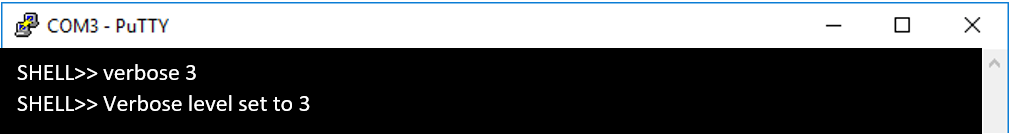
Using this command will show information from each type of debug message shown in the following table.
| Message Type | Importance | " Verbose 0" | "Verbose 1" | "Verbose 2" | "Verbose 3" |
|---|---|---|---|---|---|
|
Critical |
High |
- | x | x | x |
|
Detailed |
Medium |
- | - | x | x |
|
Misc. |
Low |
- | - | - | x |
|
On-screen Debug Info |
N/A |
- | - | - | x |
The figure below shows an example of a debug message from a face detection and recognition.
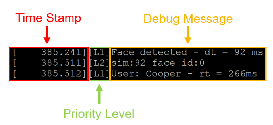
Abbreviations you can encounter in a debug message are explained in the table below
| Abbreviation | Definition |
|---|---|
| Dt | Time taken to detect face |
| Rt | Time taken to recognize face |
| Sim | Predictive accuracy/confidence value of face rec |
| Face_id | Internal face database identifier |
In addition to debug logging over serial, enabling “verbose 3” will also display some useful on-screen information as well that can be helpful when troubleshooting registration/recognition issues. An example can be seen in the images below:
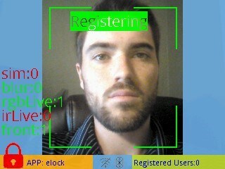
In the above example, registration is taking place, but according to the on-screen debugging info, although the face has passed the blurriness check (hence “blur: 0”), the “front face check” has passed (hence “front: 1”), and the RGB liveness check has passed (hence “rgbLive: 1”), the IR liveness check has not passed (hence “irLive: 0”). This would suggest that there may be an issue with the IR camera – likely a lighting issue.
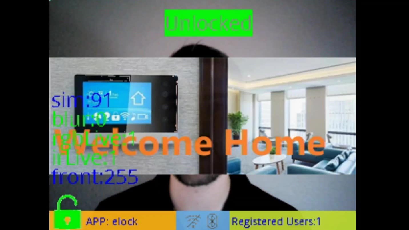
In this example, the on-screen info reflects information about the face being recognized. As shown in the screenshot, the face has been recognized with 95% similarity to the matching face in the internal database (hence “sim: 95”) and has passed both the RGB and IR liveness checks (hence “rgbLive: 1” and “irLive: 1”).
1.8 Enable Low Power Mode
For many use cases, managing power consumption is critical. Fortunately, the SLN-VIZNAS-IOT supports low power features out of the box. Low power mode functionality can be enabled or disabled through the use of the serial commands.
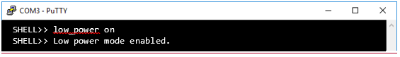
Use the command “low_power on” or “low_power off” to enable or disable the low power mode feature supported on the SLN-VIZNAS-IOT.
When low power mode is enabled, the SLN-VIZNAS-IOT will automatically sleep/hibernate in a state of much lower power consumption than normal, when no registration/deregistration is taking place and no activity is detected by the camera for ~20s.
A “recognition timeout” message like the one shown in the figure below will be displayed on screen as a warning that the SLN-VIZNAS-IOT will be entering sleep mode within the next 5 seconds.
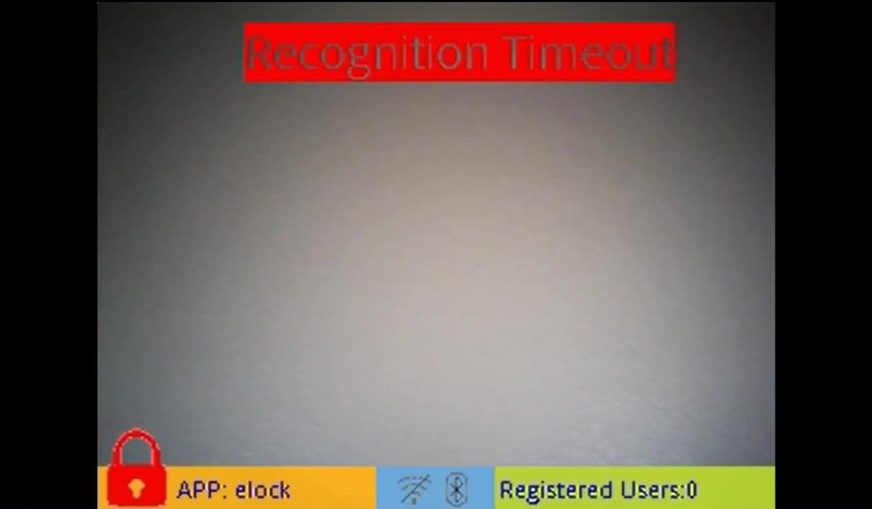
During hibernation, nearly everything but a select few peripherals is disabled in order to conserve power. As a result, the video output from the kit as well as the shell interface will not be active and will not be accessible until the board has woken up again.
Because only select peripherals are enabled during sleep mode, the SLN-VIZNAS-IOT will only wake up in response to a specific trigger(s), which by default, is the SW3 push button shown in the following figure:
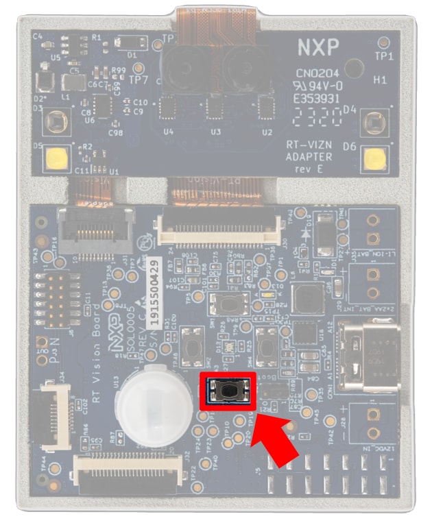
Upon detecting the trigger, the SLN-VIZNAS-IOT will automatically wake up and begin running as normal.
For more information on low power mode, see the SLN-VIZNAS-IOT User’s Guide.
2. Get Software
In addition to the contents included in the kit, the SLN-VIZNAS-IOT also comes with access to both hardware collateral and software collateral.including includes assembly files, 3D files, ODB files, and more. The software collateral includes a SDK compatible with MCUXpresso IDE that contains example projects and source code to the secure face recognition software, example Android APKs + source code for performing remote registration and Wi-Fi credential provisioning, and manufacturing tools for automated and secured flashing of the kit which can be useful in a manufacturing/production environment.
The following section details how to download these files for yourself through the NXP website for the SLN-VIZNAS-IOT.
2.1 Download the Hardware Package
Schematics including assembly files, 3Dfiles, ODB files, and more can be found on the main website for the SLN-VIZNAS-IOT near the top of the page:
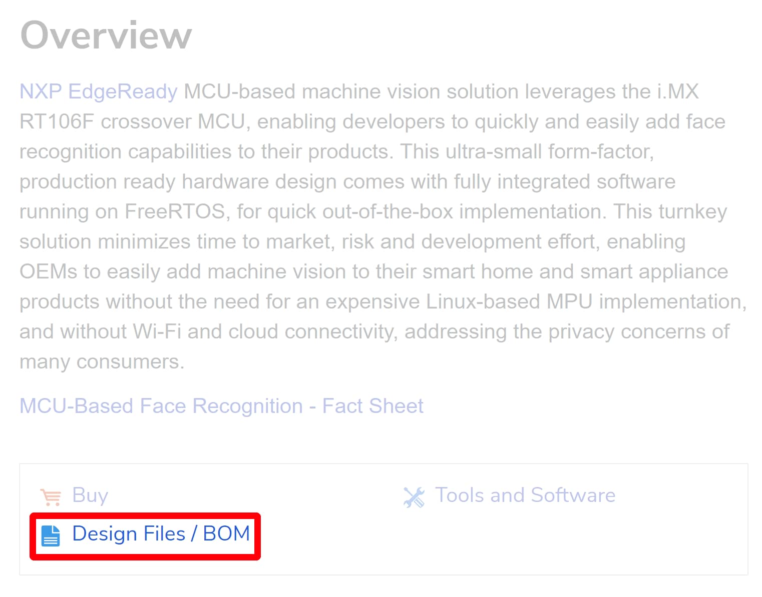
Or under Design Resources in the Quick Reference bar to the left.
2.2 Jump Start Your Design with the MCUXpresso SDK
The MCUXpresso SDK is complimentary and includes full source code under a permissive open source license for all hardware abstraction and peripheral driver software.
Click below to download a preconfigured SDK release for the SLN-VIZNAS-IOT Development Kit.
 Get MCUXpresso SDK
2.3 Install Your Toolchain
MCUXpresso IDE brings developers an easy-to-use Eclipse-based development environment for NXP’s microcontrollers based on Arm® Cortex®-M cores. It offers advanced editing, compiling and debugging features with the addition of MCU-specific debugging views, code trace and profiling, multicore debugging, and integrated configuration tools. Its debug connections support every NXP evaluation board with a variety of open-source and commercial debug probes from Arm®, P&E Micro® and SEGGER®.
 Get MCUXpresso IDE
The MCUXpresso SDK for the SLN-VIZNAS-IOT also includes support for the command-line GCC.
2.4 Download the Android Applications
For applications where companion smartphone/tablet applications might be useful, the example FaceRec Manager APK and VIZN Companion APK projects provide convenient source code to be used as a boilerplate/reference for developers looking to create their own companion apps. Both APKs and their full source code can be found under the Software and Tools section on the main page for the SLN-VIZNAS-IOT. For more information about both applications and their features, check out the SLN-VIZNAS-IOT User’s Guide.
3. Build, Run
3.1 Install the SDK
MCUXpresso SDK is a comprehensive software enablement package designed to simplify and accelerate application development with NXPs microcontrollers based on Arm® Cortex®-M cores. The MCUXpresso SDK includes production-grade software with integrated RTOS (optional), integrated stacks and middleware, reference software, and more. It is available in custom downloads based on user selections of MCU, evaluation board, and optional software components.
Before building the SLN-VIZNAS-IOT SDK example projects, the target SDK needs to be imported into MCUXpresso IDE.
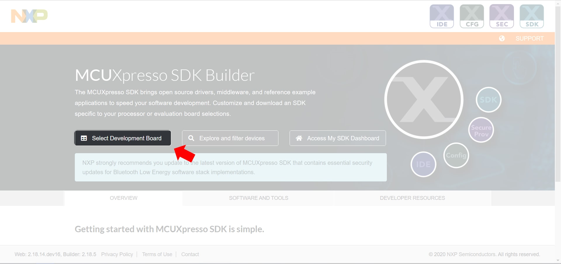
The MCUXpresso SDK for the SLN-VIZNAS-IOT can be downloaded from NXP’s SDK Builder by clicking Select Development Board and searching for “SLN-VIZNAS-IOT” in the search box.
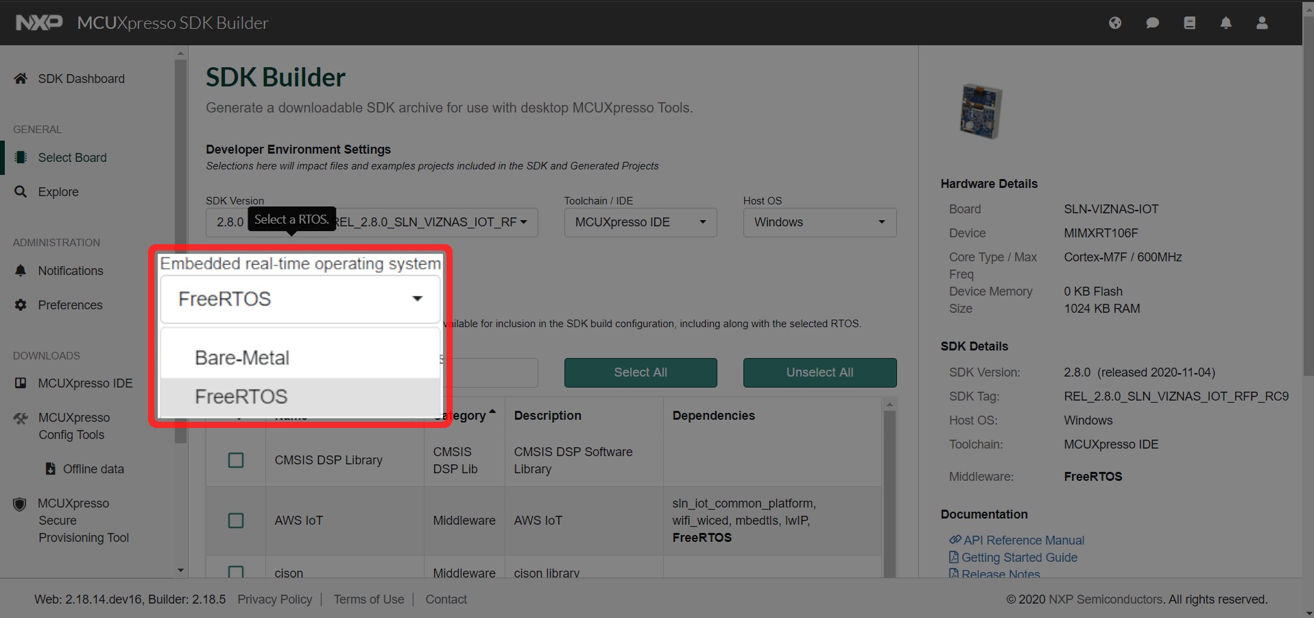
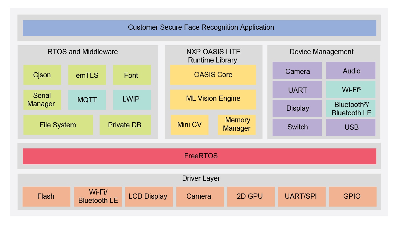
When building the SDK, be sure to select FreeRTOS under Embedded real-time operating system.
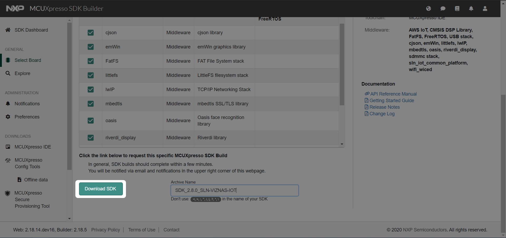
After updating the operating system, be sure to click Select All to make sure all required components get added.

With these options selected, press the Download SDK button at the bottom of the page.
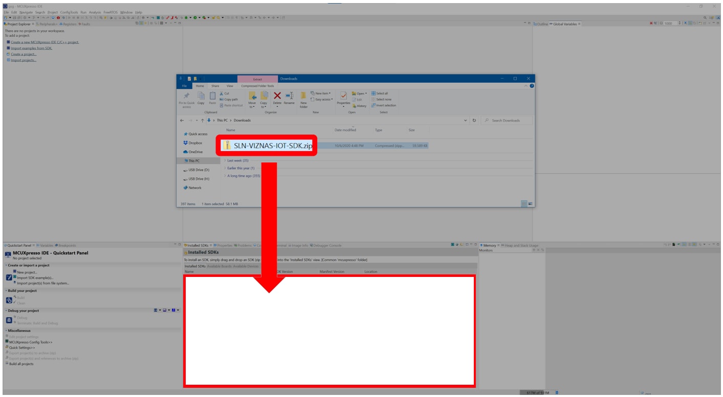
Once the SDK is downloaded, import the SDK into MCUXpresso IDE by dragging the SDK zip folder into the Installed SDKs window in MCUXpresso IDE.
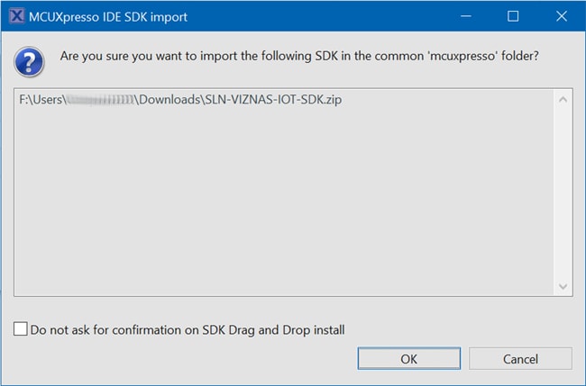
For each package, a confirmation window will pop-up. Select OK to validate.
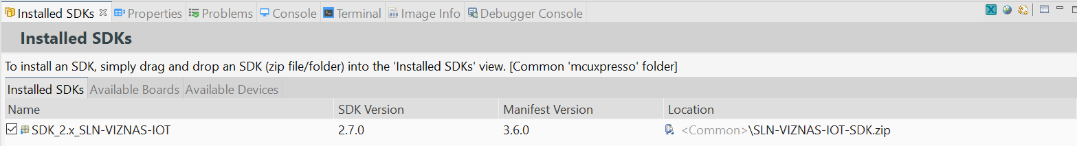
Once the package has been imported, it will be displayed in the Installed SDKs window in MCUXpresso.
3.2 Import SLN-VIZNAS-IOT Projects
The SLN-VIZNAS-IOT SDK allows you to import existing application examples as a development starting point. The following steps will show you how to import one of these example projects into MCUXpresso IDE.
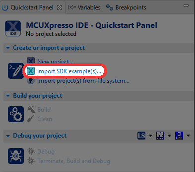
From the Quickstart Panel, select Import SDK example(s).
For each SDK you have installed into MCUXpresso, a corresponding image will be shown. Select the SLN-VIZNAS-IOT image and proceed by selecting the Next button.
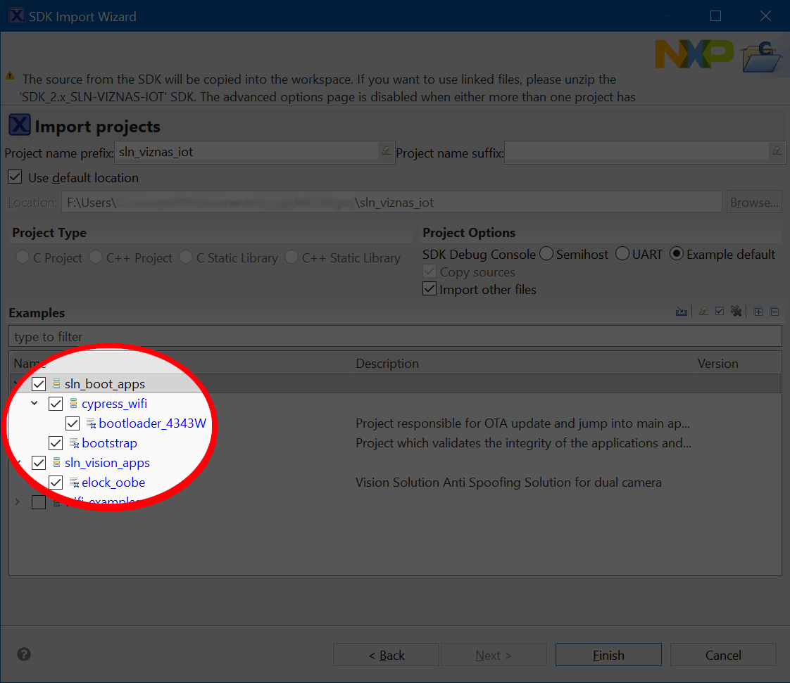
The import wizard will then display all the example applications that are available to import.
For this guide we will be focused primarily on the sln_viznas_iot_elock_oobe
application. This is the application that comes flashed by default on your
SLN-VIZNAS-IOT kit.
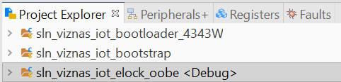
Once the projects have successfully been imported, they will be listed in the project explorer ready to be built and run.
3.3 Increase Clock Drive Strength
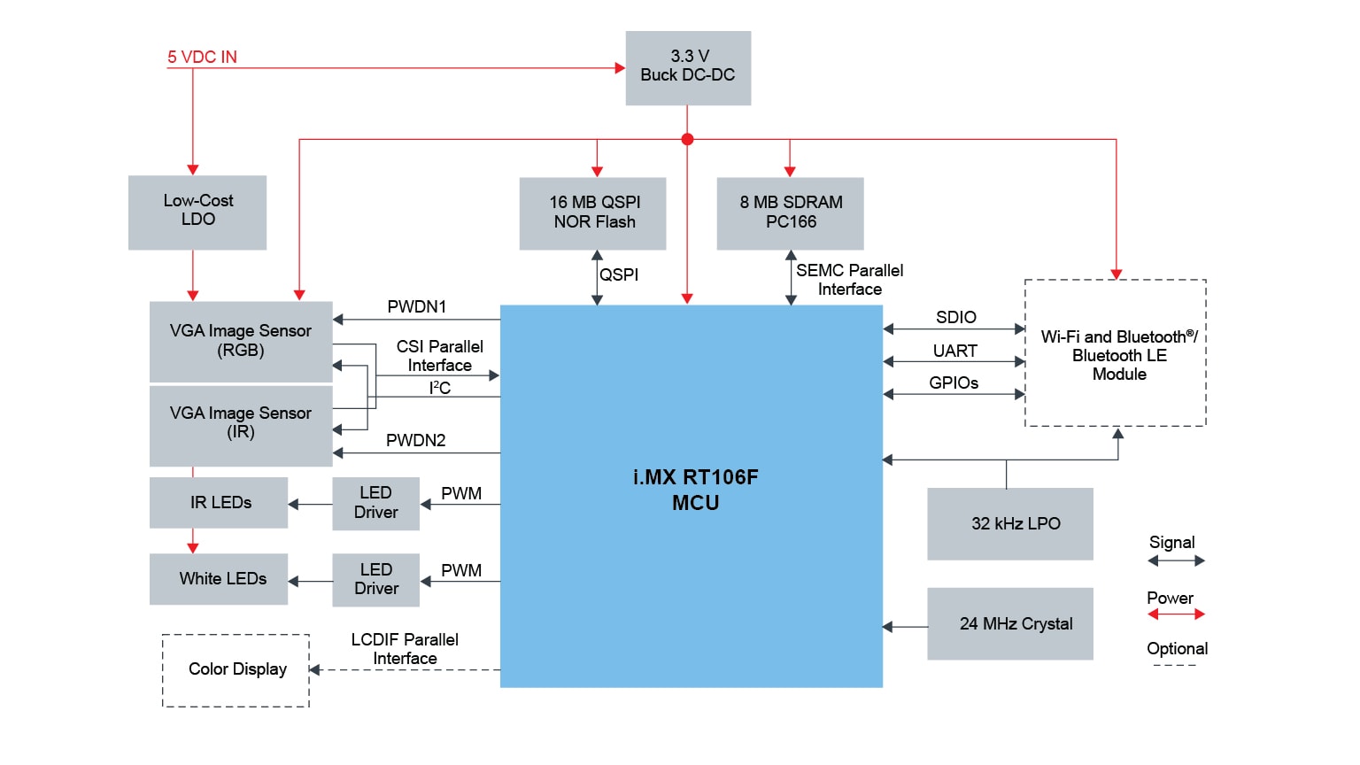
By default, the sln_viznas_iot_elock_oobe application uses a lower clock rate and clock drive strength for the cameras than the 106F is capable of in order to maintain EMC compliance (see RT106F VISION CROSSOVER PROCESSOR OVERVIEW). This lower clock rate results in a lower FPS and overall recognition performance.
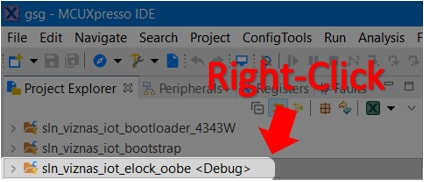
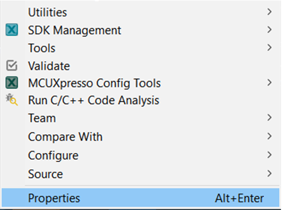
To make it easy for developers to utilize the full performance capabilities of the camera, the sln_viznas_iot_elock_oobe project provides a convenient preprocessor macro which can be configured to increase or decrease the camera clock’s drive strength and clock rate. To configure this preprocessor macro, right click on the sln_viznas_iot_elock_oobe project in the Project Explorer pane as shown in the figure below and select Properties, found near the bottom of the context menu:
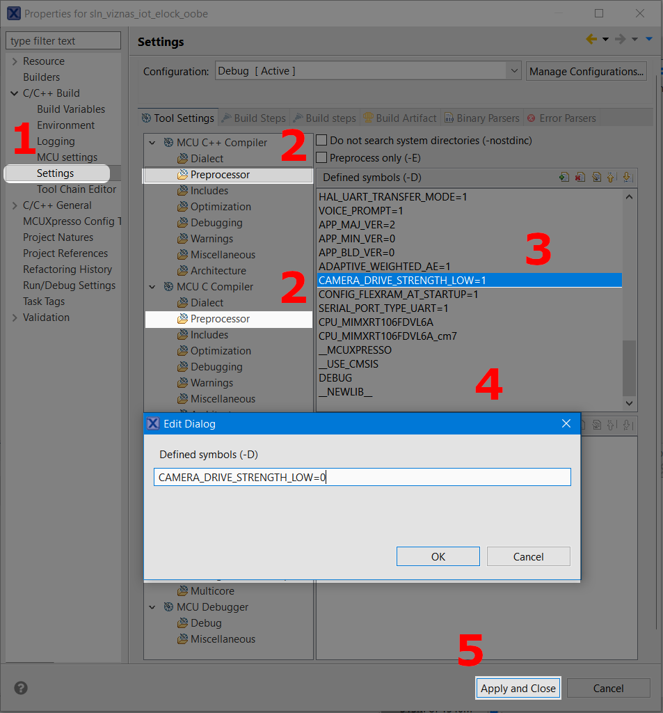
Clicking the Properties option will open up a new window which looks like the one shown in Figure 22: Properties Window. From there:
- Click Settings
- Click MCU C++ Compiler → Preprocessor
- Double click the CAMERA_DRIVE_STRENGTH_LOW macro
- Change the value from 1 to 0 and click OK
Repeat the previous steps for the CAMERA_DRIVE_STRENGTH_LOW preprocessor macro found under MCU C COMPILER → Preprocessor, then003A.
5. Click Apply and Close
3.4 Build a SLN-VIZNAS-IOT Project
The bootstrap project is the first application that is booted. The bootstrap is a minimal FreeRTOS application that is responsible for image verification.
The bootloader project is a second stage bootloader that manages jumping into the E-Lock OoBE application. This application can be used for any additional bootloader functionality needed for the product. The bootloader is also responsible for Mass Storage Device drag-and-drop firmware updates via USB.
The E-Lock OoBE is the out-of-box application used to demonstrate the capabilities of the Oasis Lite machine learning engine for secure face recognition. This is the application (in addition to the bootloader and bootstrap) that is flashed on your SLN-VIZNAS-IOT kit by default.
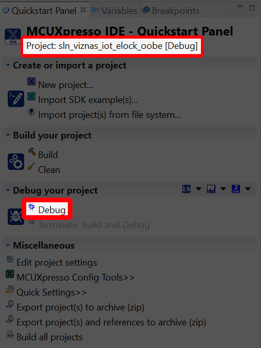
From the Quickstart Panel, select the option Build to start the compilation and linking of the application currently highlighted in the Project Explorer pane.
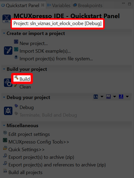
This will need to be done for the sln_viznas_iot_elock_oobe as well as the
sln_viznas_iot_bootloader and sln_viznas_iot_bootstrap if you
intend to flash those
projects.
Wait for MCUXpresso to finish the build process. This should take a relatively short time due to the small size of the application.
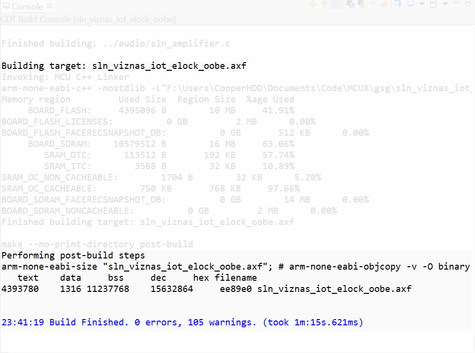
If you received a message like the one shown above, your SLN-VIZNAS-IOT project has successfully been built.
3.5 Flash and Debug SLN-VIZNAS-IOT Project
With the elock_oobe project compiled, it is now time to program its associated binary into flash.
Flashing and debugging the SLN-VIZNAS-IOT kit WILL REQUIRE a
Segger J-Link with a 9-pin
Cortex-M Adapter and V6.62a or newer of the J-Link
Software and Documentation Pack found on the Segger website
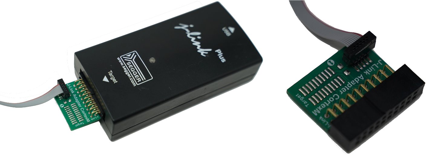
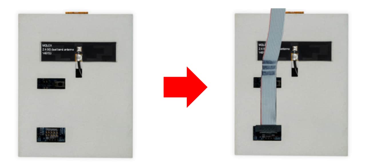
To begin the process of flashing the kit, attach your J-Link debug probe into the header shown below.
Next, select the Debug option found under the QuickStart panel in MCUXpresso to start the process of loading the binary into the flash and begin debugging. Similar to the Build option, Debug will only flash and debug the project currently highlighted in the Project Explorer panel.
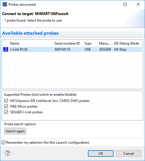
Select the J-Link probe that is connected to your kit and press OK.
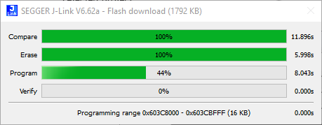
This will launch the flashing tool and proceed to flash the binary associated with the currently selected project.
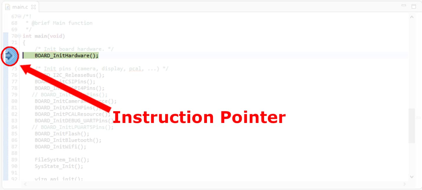
Once flashed, the program should automatically halt at main, indicated by the first instruction in main being highlighted and pointed to.
Finally, press the Run button found in the toolbar to begin running the application. You will also find buttons to Terminate, Step In, Step Out, and Step Over in this same toolbar.

To learn more about debugging in MCUXpresso, check out the MCUXpresso User Guide found here
Push Button Table
Push Button Table
The push buttons on the SLN-VIZNAS-IOT kit have many useful functions to make interacting with the kit more user-friendly. Learn more about these functions by checking out the table below.
| Button | Function | Description |
|---|---|---|
| SW1 | Toggle GUI | Toggles the GUI on or off. |
| SW2 | Manual Deregister | Triggers the deletion of the next registered face encountered by the kit. |
| SW3 | Toggle IR/RGB Output | Toggles whether output from the RGB or IR camera is shown. Does not affect which cameras are in use. |
| SW4 | Manual Register | Triggers registration of the next face encountered by the kit. |
Tera Term Tutorial
Tera Term Tutorial
Tera Term is a very popular open source terminal emulation application. This program can be used to display information sent from your NXP development platform's virtual serial port.
- Download Tera Term from SourceForge. After the download, run the installer and then return to this webpage to continue
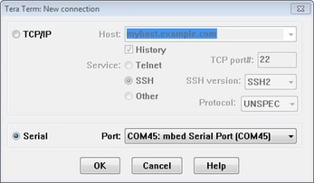
- Launch Tera Term. The first time it launches, it will show you the following dialog. Select the serial option. Assuming your board is plugged in, there should be a COM port automatically populated in the list
- Configure the serial port settings (using the COM port number identified earlier) to 115200 baud rate, 8 data bits, no parity and 1 stop bit. To do this, go to Setup → Serial Port and change the settings
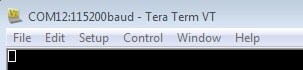
- Verify that the connection is open. If connected, Tera Term will show something like below in it's title bar
- You're ready to go
PuTTY Tutorial
PuTTY Tutorial
PuTTY is a popular terminal emulation application. This program can be used to display information sent from your NXP development platform's virtual serial port.
- Download PuTTY using the button below. After the download, run the installer and then return to this webpage to continue.
- Launch PuTTY by either double clicking on the *.exe file you downloaded or from the Start menu, depending on the type of download you selected.
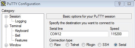
- Configure In the window that launches, select the Serial radio button and enter the COM port number that you determined earlier. Also enter the baud rate, in this case 115200.
- Click Open to open the serial connection. Assuming the board is connected and you entered the correct COM port, the terminal window will open. If the configuration is not correct, PuTTY will alert you.
- You're ready to go
Design Resources
Board Documents
Chip Documents
Software
- MCUXpresso SDK with FreeRTOS support
- MCUXpresso IDE
- MCUXpresso Config Tools
- VIZNAS SDK including NXP OASIS Lite machine learning vision engine
Support
Learn more about the SLN-VIZNAS-IOT with design tips, training documents, and the NXP Community. If you need additional help, contact NXP Support.
Communities
Connect with other engineers and get expert advice on designing with the SLN-VIZNAS-IOT on one of our community sites.
On this page
- 1.1
Unboxing
- 1.2
Power On
- 1.3
Access the Camera
- 1.4
Register Face
- 1.5
Liveness Detection and Anti-Spoofing
- 1.6
Connect to Serial CLI
- 1.7
Enable Verbose Mode
- 1.8
Enable Low Power Mode
- 2.1
Download the Hardware Package
- 2.2
Jump Start Your Design with the MCUXpresso SDK
- 2.3
Install Your Toolchain
- 2.4
Download the Android Applications