- No Longer Manufactured
- Getting Started with the OM13588
Getting Started with the OM13588
Contents of this document
-
Get Software
-
Build, Run
-
Create
Sign in to save your progress. Don't have an account? Create one.

Purchase your USB Type-C Shield Board for Kinetis FRDM and LPC Boards
1. Get Software
1.1 Download MCUXpresso SDK with USB PD
The MCUXpresso SDK is complimentary and includes full source code under a permissive open source license for all hardware abstraction and peripheral driver software.
The MCUXpresso SDK contains USB Type-C Power Delivery middleware to support rapid development.
Click below for instructions on how to use the SDK Builder to create a custom SDK package with USB Power Delivery support.

Create MCUXpresso SDK
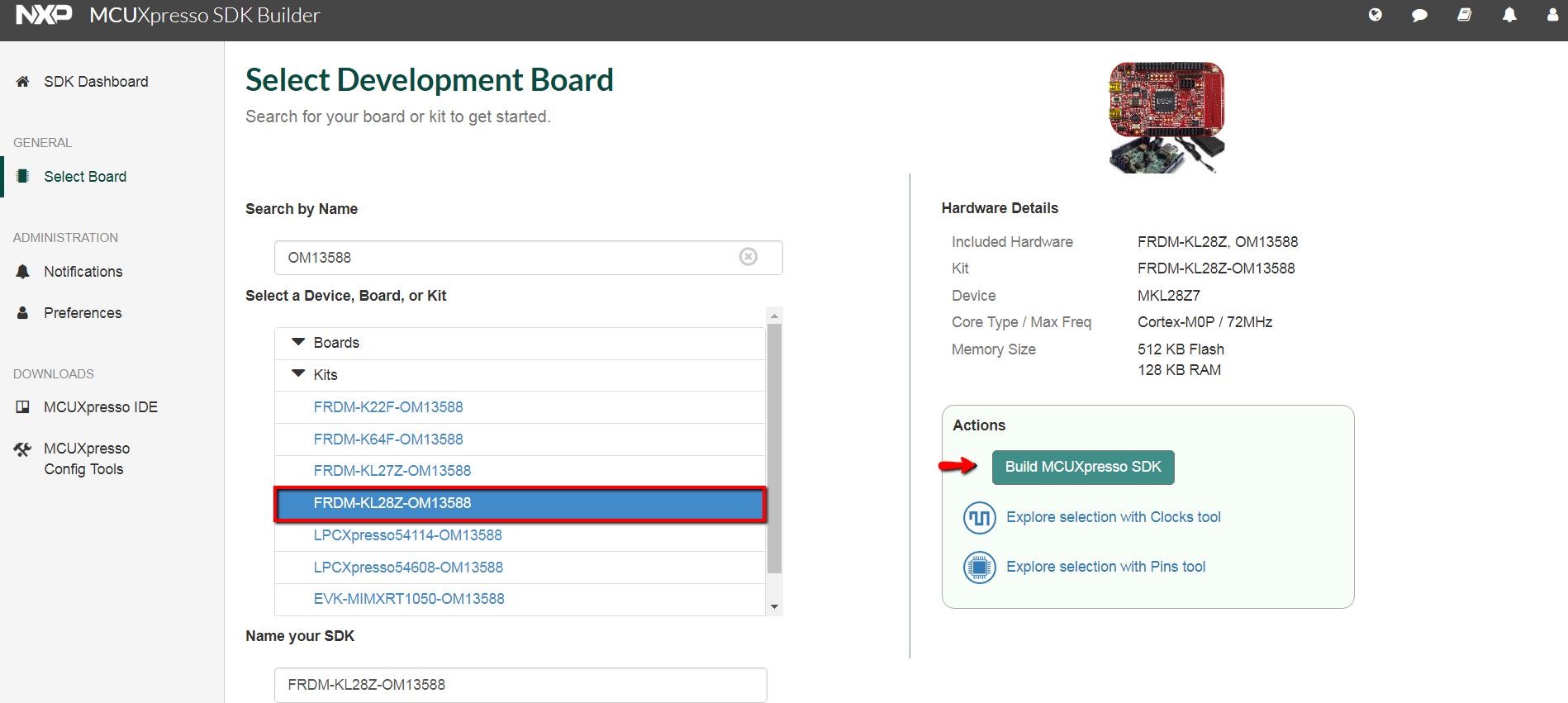
Use the online MCUXpresso SDK Builder to create a custom SDK package for the FRDM-KL28Z board.
- Open a web browser and navigate to the MCUXpresso homepage MCUXpresso SDK Builder
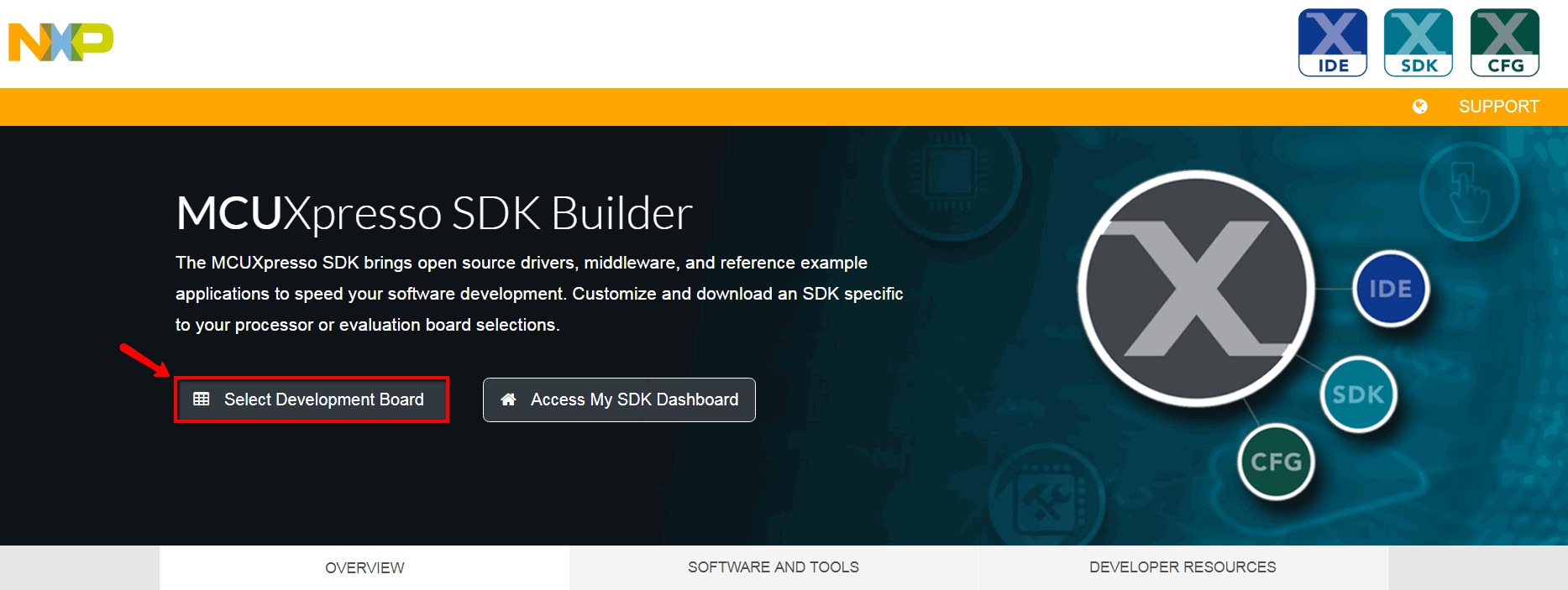
- Click on “Select Development Board” to download a customized SDK
- After being redirected to nxp.com login page. Enter your account information or register for a new account
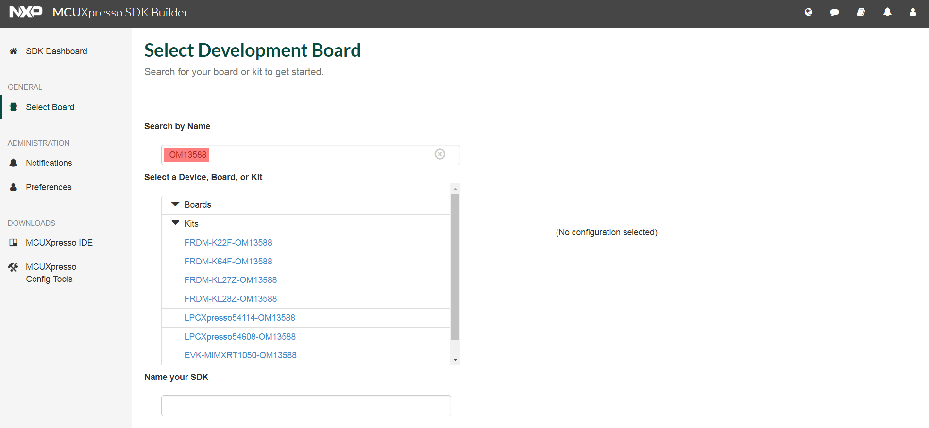
- Back on the Select Development Board page, search for the USB PD board name (example: OM13588)
- Choose any board from the list and provide a name for the configuration. Then, click “Build MCUXpresso SDK”
-
At the SDK Builder section, select the following Configuration Settings
-
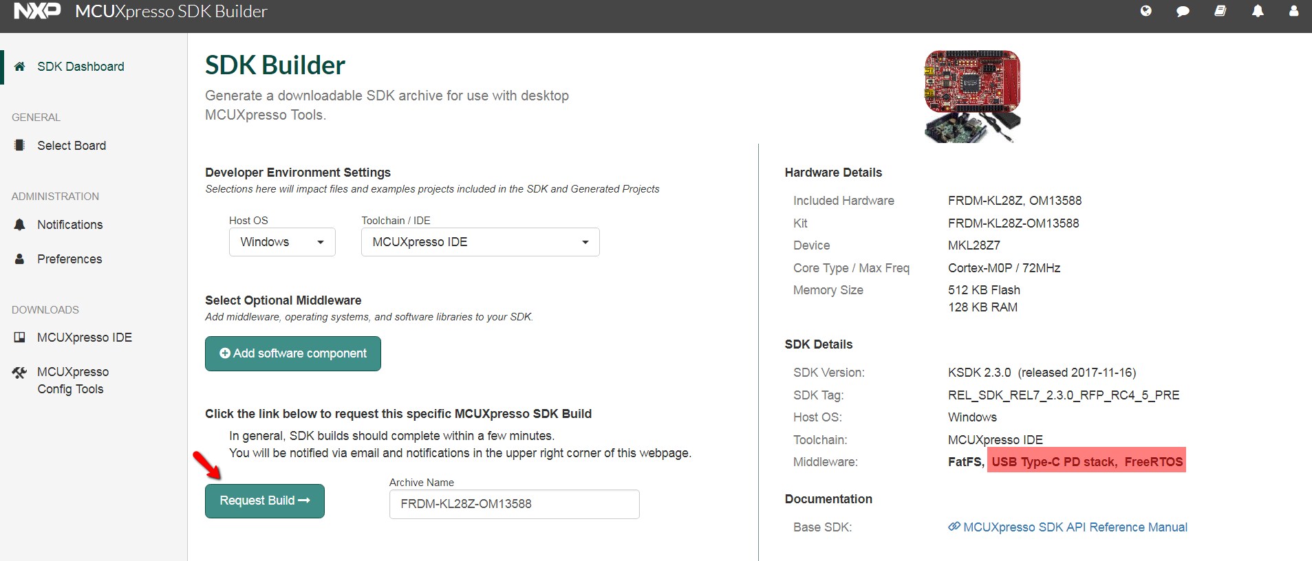
Developer Environment Settings
- Host OS → Windows
- Toolchain / IDE → MCUXpresso IDE
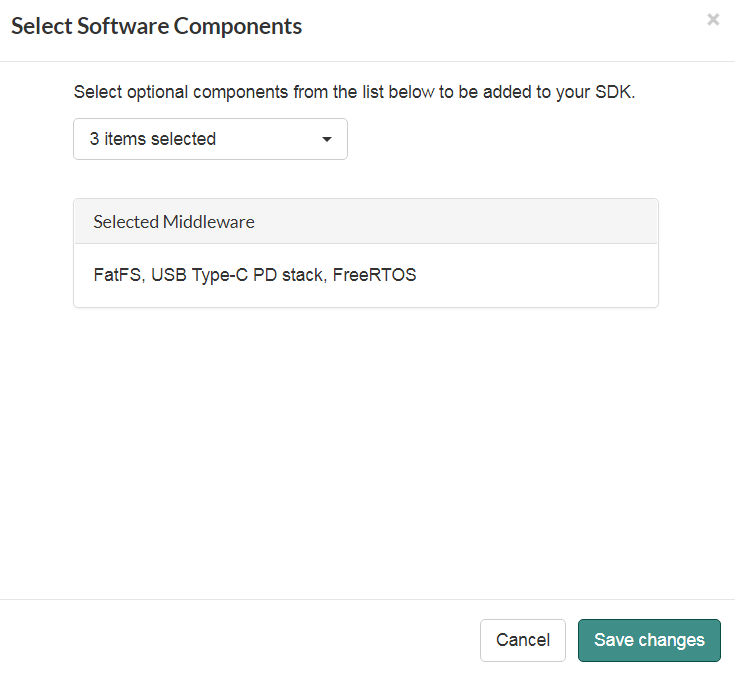
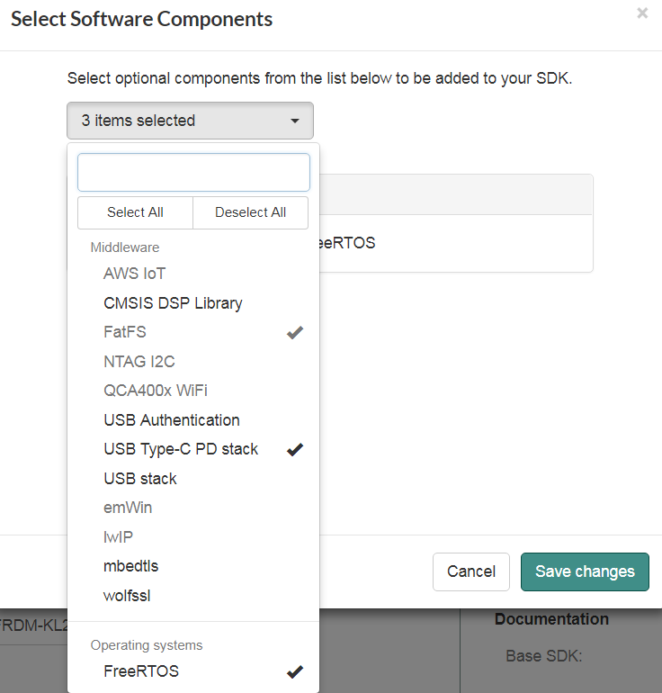
- Select Optional Middleware – click Add Software component, select FatFs, USB Type-C PD stack, FreeRTOS. Then click Save Change
-
Developer Environment Settings
- Select “Download Now” to download the SDK
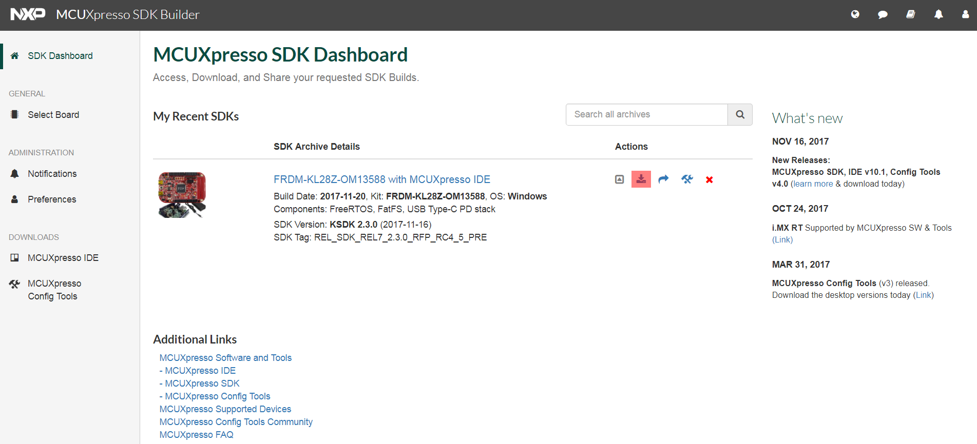
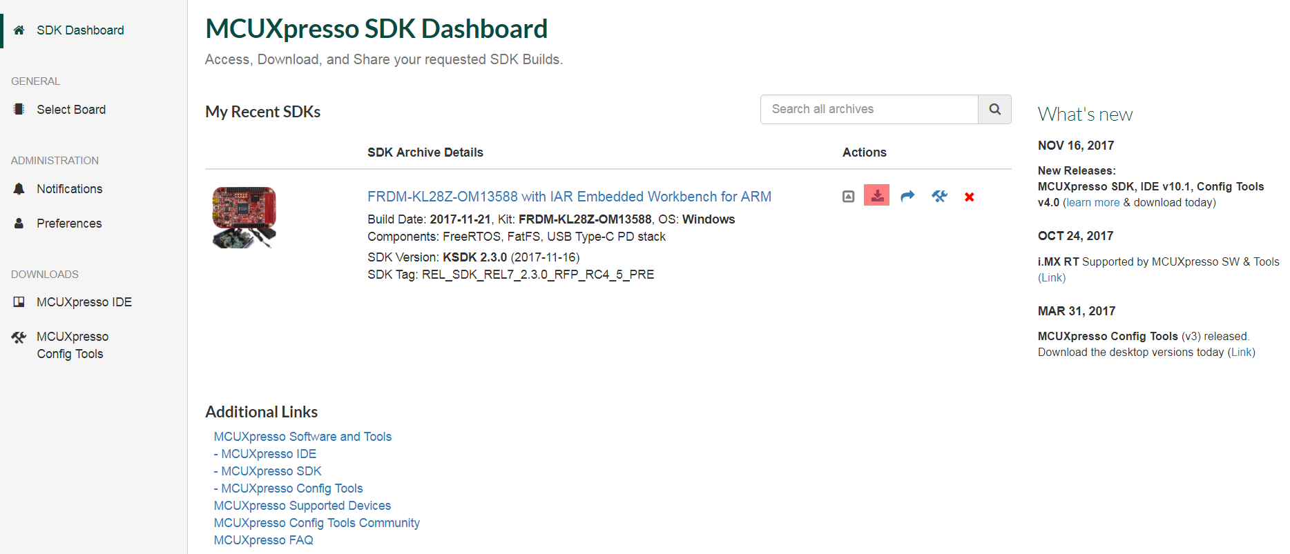
Note: you may see “Request to Build” instead, so click on that, and after the package gets built, there will be a new download in the SDK Dashboard section - Inside the SDK Dashboard look for the recently built SDK then click Download icon
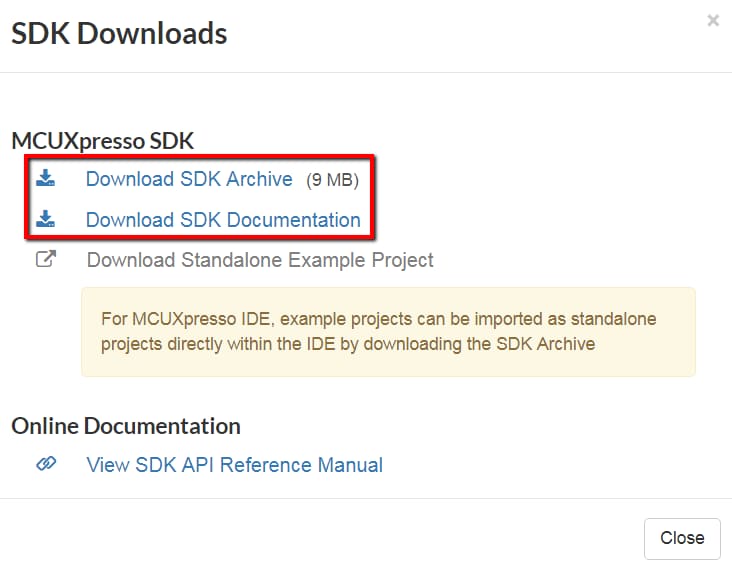
- Download the SDK Archive and SDK Documentation pop-up
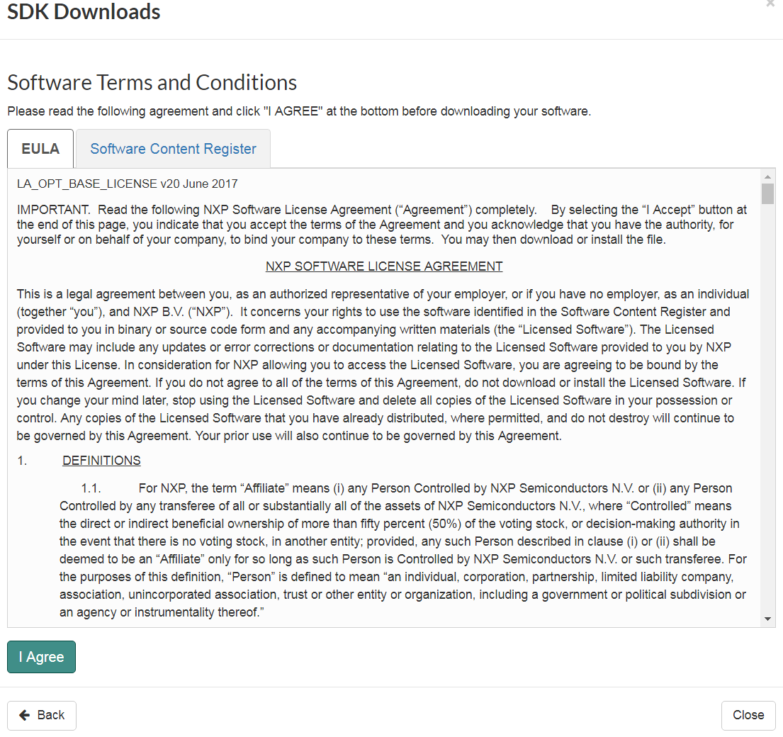
- Agree to Licensing Terms and Conditions
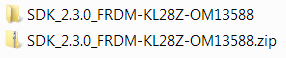
- Unzip SDK to a folder (i.e.,
SDK_2.3.0_FRDM-KL28Z_OM13588)
Create IAR SDK
Use the online MCUXpresso SDK Builder to create a custom SDK package for the FRDM-KL28Z board.
- Open a web browser and navigate to the MCUXpresso homepage MCUXpresso SDK Builder
- Click on “Select Development Board” to download a customized SDK
- After being redirected to nxp.com login page. Enter your account information or register for a new account.
- Back Select Development Board page, search for the USB PD board name (example: OM13588).
- Choose any board from the list and provide a name for the configuration. Then, click “Build MCUXpresso SDK.”
-
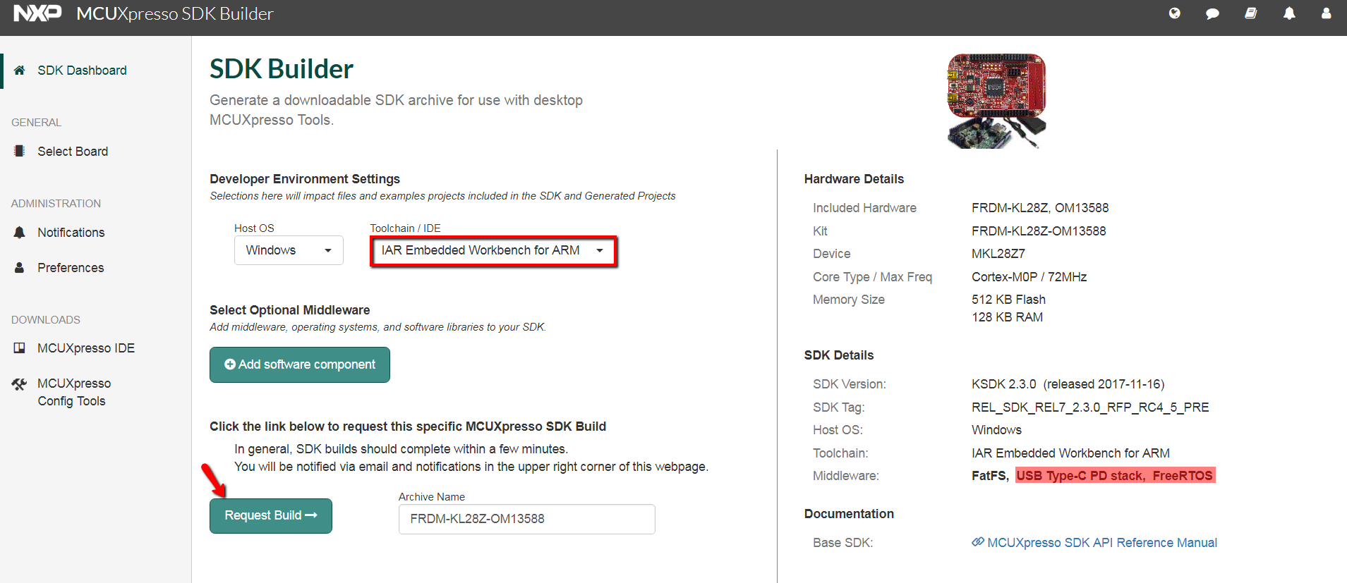
At the SDK Builder section, select the following Configuration Settings
-
Developer Environment Settings
- Host OS → Windows
- Toolchain / IDE → IAR Embedded Workbench
- Select Optional Middleware → click Add Software component, select: FatFs, USB Type-C PD stack, FreeRTOS. Then click Save Change
-
Developer Environment Settings
- Select “Download Now” to download the SDK
- Note: you may see “Request to Build” instead, so click on that, and after the package gets built, there will be a new download in the SDK Dashboard section
- Inside the SDK Dashboard look for the recently built SDK then click Download icon
- Download the SDK Archive and SDK Documentation pop-up
- Agree to Licensing Terms and Conditions
- Unzip SDK to a folder (i.e.,
SDK_2.3.0_FRDM-KL28Z_OM13588)
1.2 Install Your Toolchain
NXP offers a complimentary toolchain called MCUXpresso IDE

Want to use a different toolchain?
No problem. The MCUXpresso USB Power Delivery SDK includes support for IAR Embedded Workbench IDE .
1.3 MCUXpresso Config Tools
The MCUXpresso Config Tool is an integrated suite of configuration tools that guide users in creating new MCUXpresso SDK projects, and also provides pin and clock tools to generate initialization C code for custom board support.
 Get MCUXpresso Config Tools
1.4 PC Configuration
Many of the example applications output data over the MCU UART so you'll want to make sure that the driver for the board's virtual COM port is installed. Before you run the driver installer, you MUST have the board plugged into your PC.
With the serial port driver installed, run your favorite terminal application to view the serial output from the MCU's UART. Configure the terminal to 115200 baud rate, 8 data bits, no parity, and one stop bit. To determine the port number of the FRDM-KL28Z virtual COM port, open the device manager and look under the "Ports" group.
Not sure how to use a terminal application? Try one of these tutorials: Tera Term Tutorial, PuTTY Tutorial
2. Build, Run
2.2 Explore the USB PD MCUXpresso SDK Example Code
The MCUXpresso SDK comes with an extensive list of example applications code.
The USB Power Delivery SDK middleware provides several example codes compatible with the USB Type-C PD Shield Board located at <sdk_install_directory>/boards/frdmkl28z_om13588/usb_examples</sdk_install_directory>
To learn more about specific example code, open the readme.txt file in an example's directory.
2.3 Build, Download USB PD SDK Example
If one or more of the demo applications or driver examples sounds interesting, you probably want to know how you can build and debug yourself. The Getting Started with MCUXpresso SDK guide provides easy, step-by-step instructions on how to configure, build, and debug demos for all toolchains supported by the SDK.
Use the guide below to learn how to open, build, and debug a USB PD example application using the MCUXpresso IDE.
Ultra-Low-Power
Use MCUXpresso IDE
The following steps will guide you through open. Compile and download the usb_pd application to the FRDM-KL28Z.
Import the MCUXpresso SDK
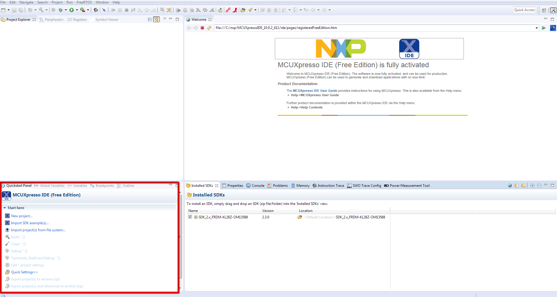
- Open up the MCUXpresso IDE
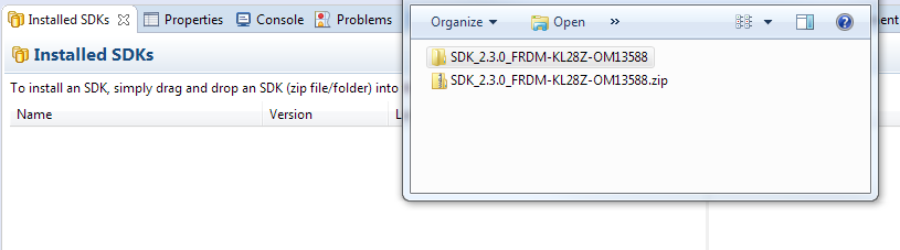
- Switch to the Installed SDKs view within the MCUXpresso IDE window
- Open Windows Explorer, drag and drop the FRDM-KL87Z-OM13588 SDK (unzipped) file into the Installed SDKs view
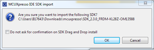
- When the following pop-up appears, click OK to continue the import
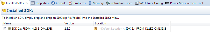
- The installed SDK will be displayed in the Installed SDKs view as shown below:
Build an Example Application
The following steps guide you trough opening the usb-pd example.
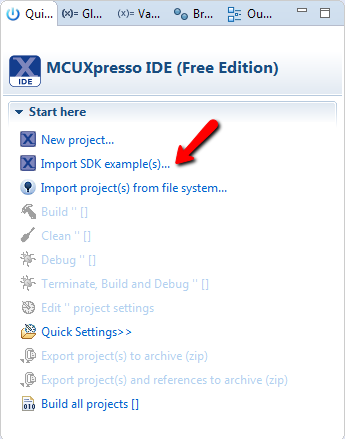
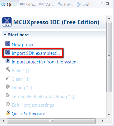
- Find the Quickstart Panel in the lower left-hand corner
- Then click on import SDK examples(s)...
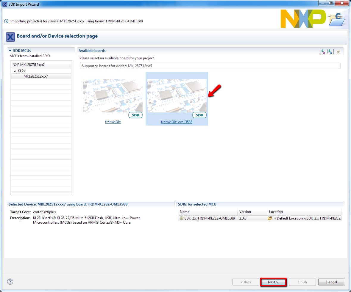
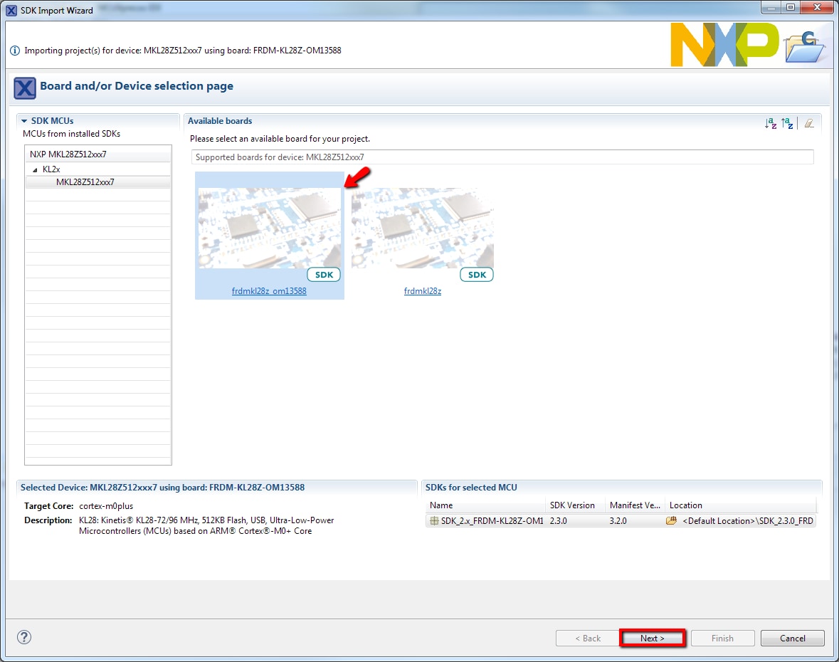
- Click on the frdmkl28z_om13588 board image to select that you want to import an example project that can run on that board, then click Next
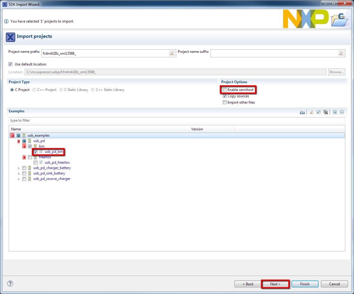
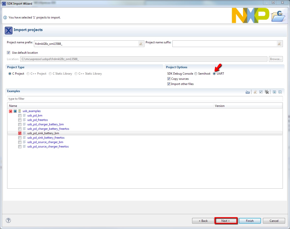
- Use the arrow button to expand the usb_examples category, expand the usb_pd section, then select one of the projects usb_pd_bm bare metal or usb_pd_freertos freertos. To use the UART for printing (instead of the default semihosting), clear the “Enable semihost” under the project options. Then, click Next
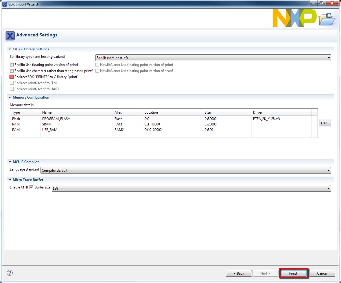
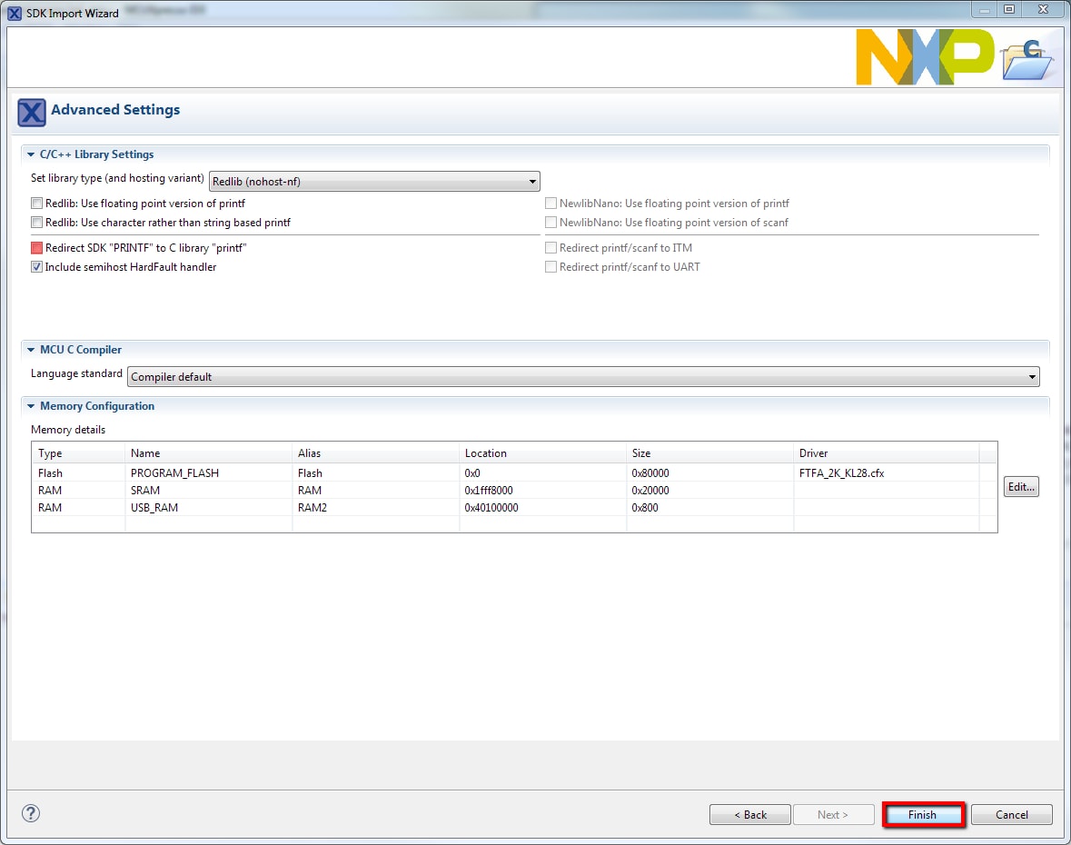
- On the Advanced Settings wizard, clear the checkbox Redirect SDK “
PRINTF” to C library “printf” to use the MCUXpresso SDK console functions for printing instead of generic C library ones. Then click on Finish - Now build the project by clicking on the project name and then click on the Build icon
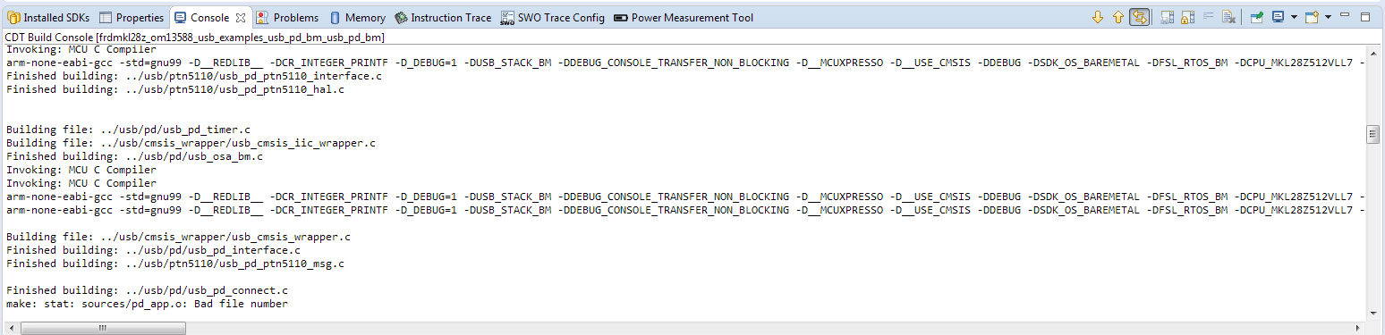
- You can see the status of the build in the Console tab
Run an Example Application
- With the project compiled, you can now flash it to the board and run it
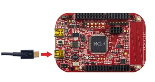
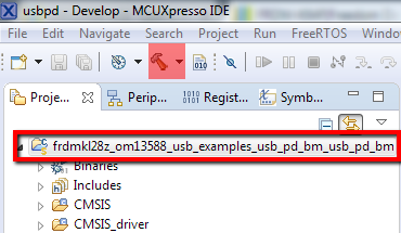
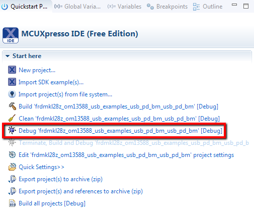
- Make sure that the FRDM-KL28Z board is plugged in through the SDA USB port, and click on Debug ‘
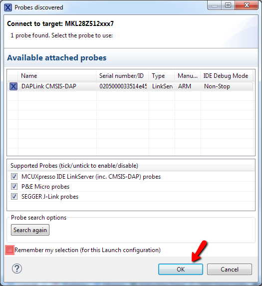
frdmkl28z_om13588_usb_examples_usb_pd_bm’ [Debug] - MCUXpresso IDE probes for connected boards and should find the USB – OpenSDA DAP Link debug probe that is part of the integrated OpenSDA circuit on the FRDM-KL28Z. Uncheck the Remember my selection. Click on OK to continue
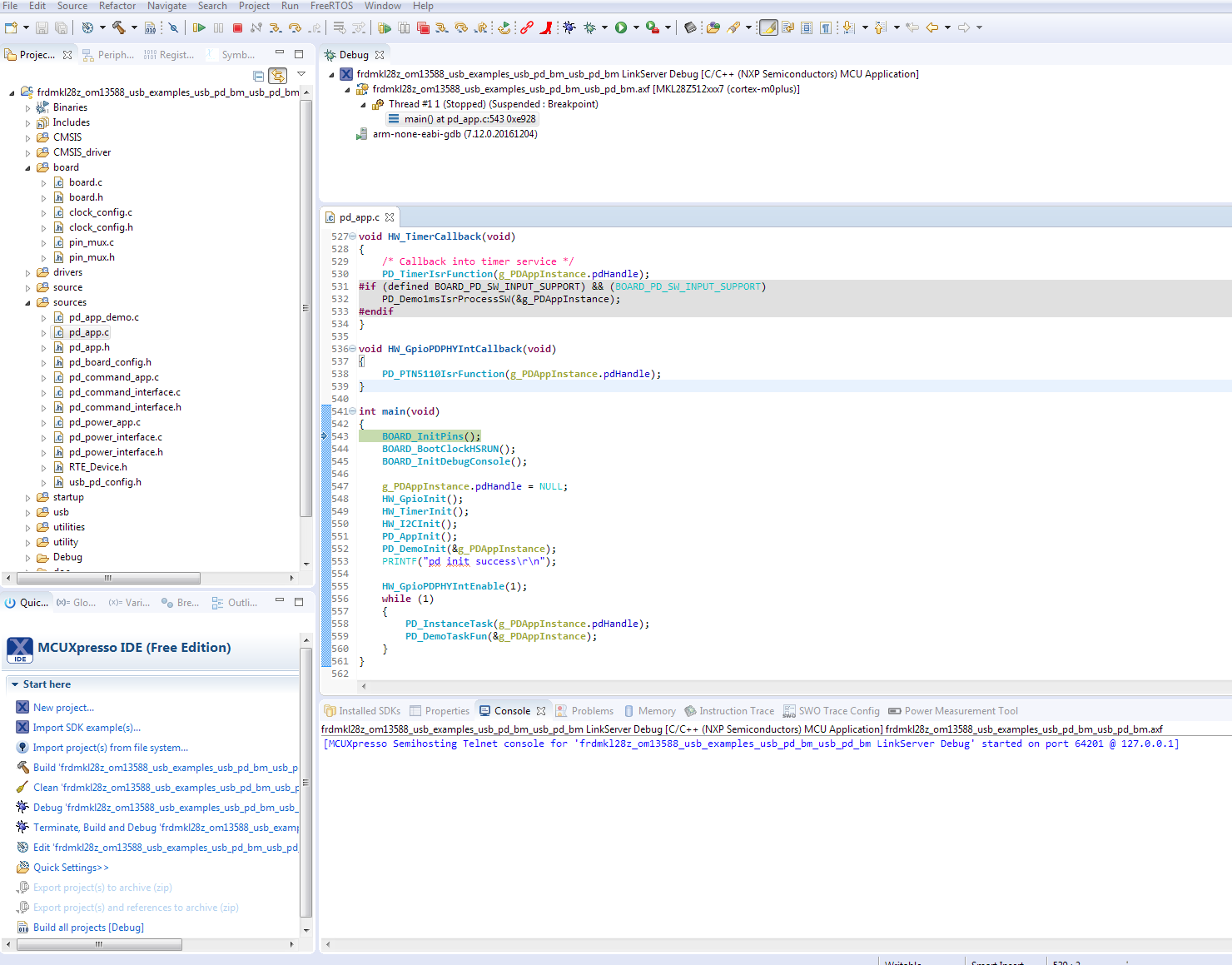
- The board gets flashed with the firmware, and the debugger starts
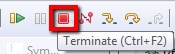
- Click the Terminate button and disconnect the device
The USB Type-C PD stack needs one provider and one consumer, repeat steps 1 through 6 to program the second board.
2.5 Run usb_pd software example
Use the guide below for a step-by-step guide on how to assemble the hardware and running the usb_pd DRP example application.
Run usb_pd Example
The following steps show how to connect and run the usb_pd example application.
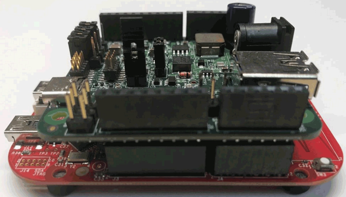
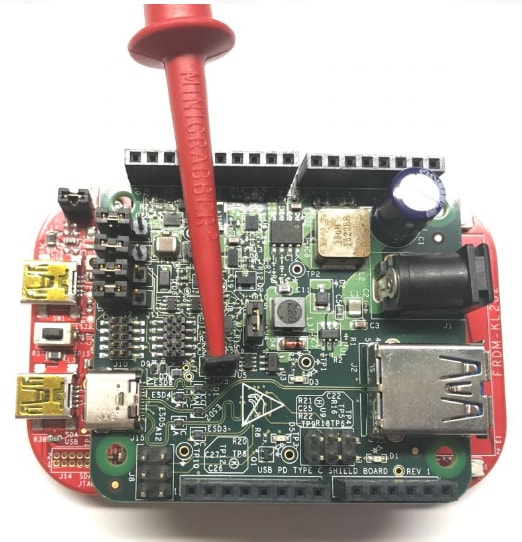
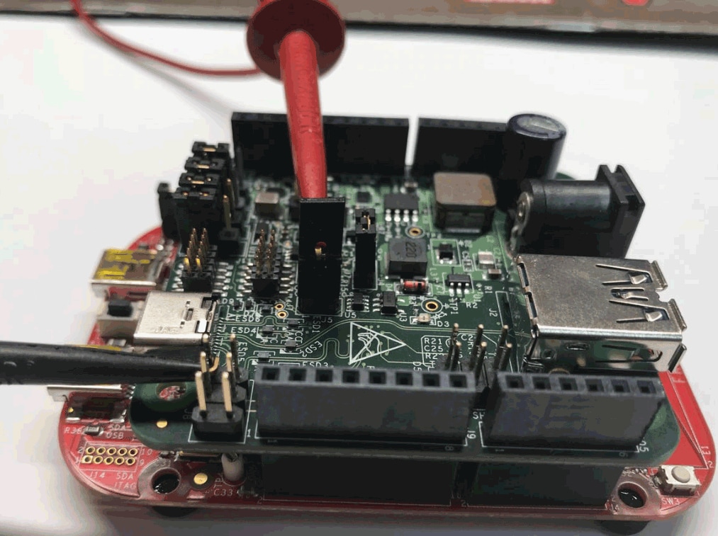
- Align the pins on the USB Type-C Shield to the headers of the FRDM-KL28Z so that the two boards mate correctly and press them together
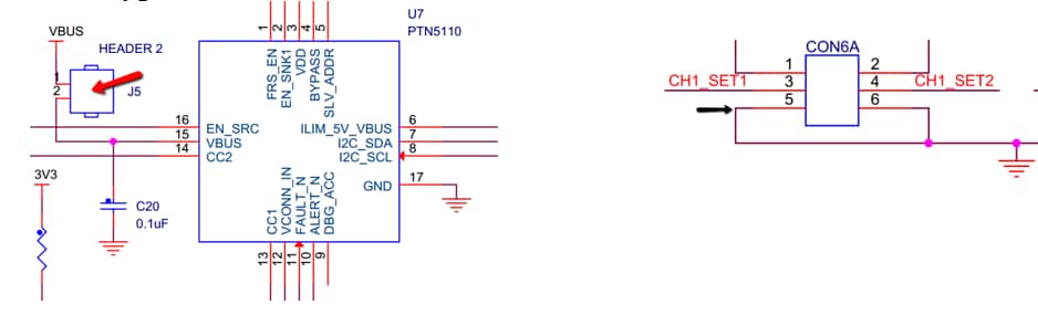
- Change USB PD Shield jumpers
J11andJ12to the 2-3 position - To monitor VBUS changes, connect a voltmeter between
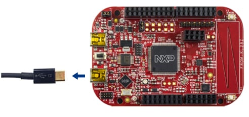
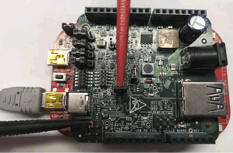
J5andJ8pin 6 at the USB Type-C Shield - Attach the FRDM-KL28Z OpenSDA USB cable
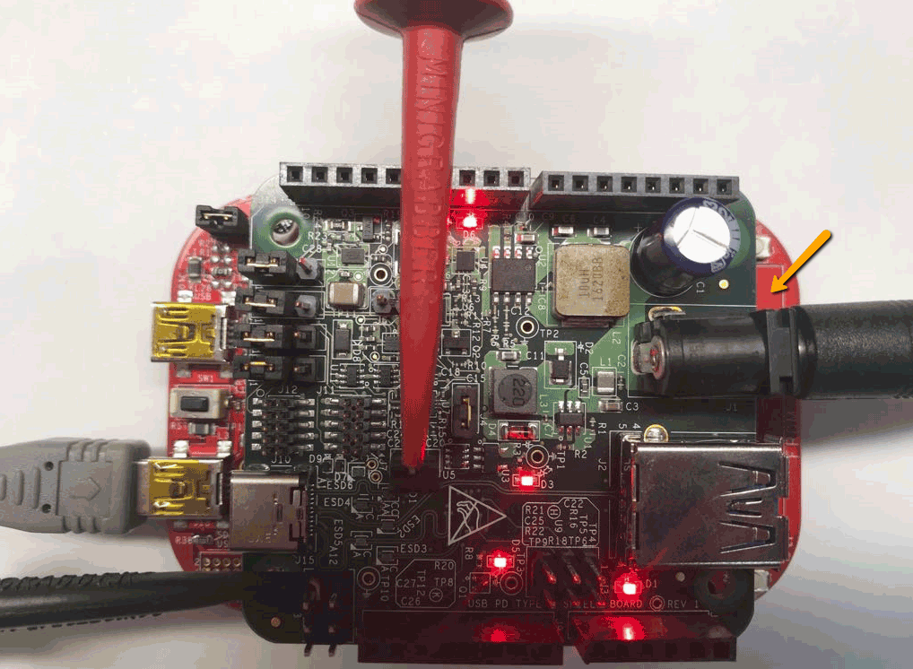
- Power the USB Type-C Shield by connecting the 9V power source to
J1jack - Open a terminal application on the PC (such as PuTTY or TeraTerm) using the debug COM port you determined earlier. Configure the terminal with these settings:
- 115200 baud rate
- No parity
- 8 data bits
- 1 stop bit
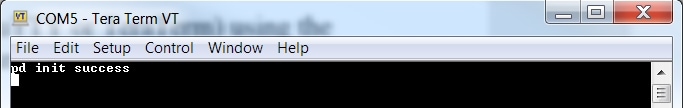
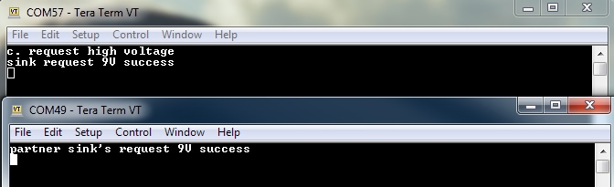
- Press the Reset button; the following message should appear on the terminal
- Repeat steps 1 through 6 for the second FRDM-KL28Z / USB Type-C Shield setup
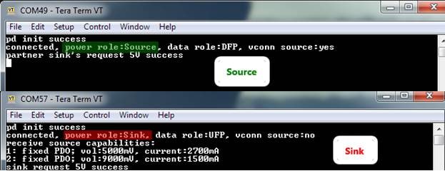
- Connect a USB Type-C cable between the two boars, one works as a sink and the second one becomes the source. To identify which is which go to the terminals
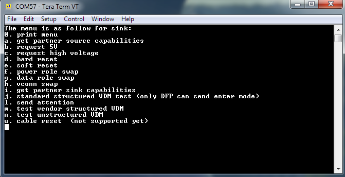
- Write ‘0’ at the sink terminal. The following menu will be printed in the debug console
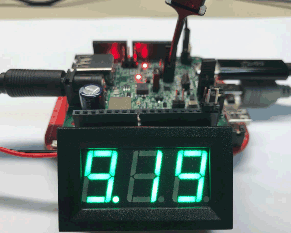
- Input ‘c’ to make a 9 V request. After the request is complete, the voltmeter shows approximately 9 V
For extra information, please use the "MCUXpresso SDK USB Type-C PD Stack User's Guide" located at the document folder
3. Create
Clone a USB PD example project from MCUXpresso SDK
Option A: Use the MCUXpresso IDE to clone an example project
3.1 Use MCUXpresso IDE
- Open MCUXpresso IDE
- Click Import SDK Example(s)... from the Quick Start Panel
- Select the FRDM-KL28Z-OM13588 board in the Import Wizard. Then, select Next
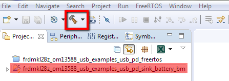
- Use the arrow button to expand the
usb_examplescategory, and then click the checkbox next tousb_pd_sink_battery_bmto choose that project. Select UART as the SDK Debug Console under the project options. Then, click Next - On the Advanced Settings wizard, clear the checkbox Redirect SDK “
PRINTF” to C library “printf” to use the MCUXpresso SDK console functions for printing instead of generic C library ones. Then click on Finish - Now build the project by clicking on the project name and then click on the Build icon
3.2 Use MCUXpresso Config Tools
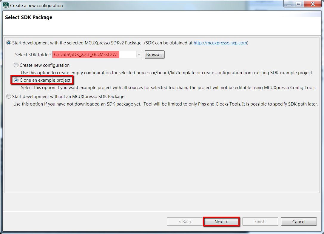
- Open the MCUXpresso Config Tool
- In the wizard that comes up, browse to the place where the MCUXpresso SDK previously unzipped, and then select the “Clone an example project” radio button and click Next
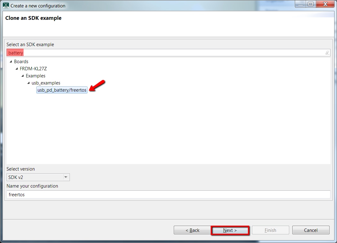
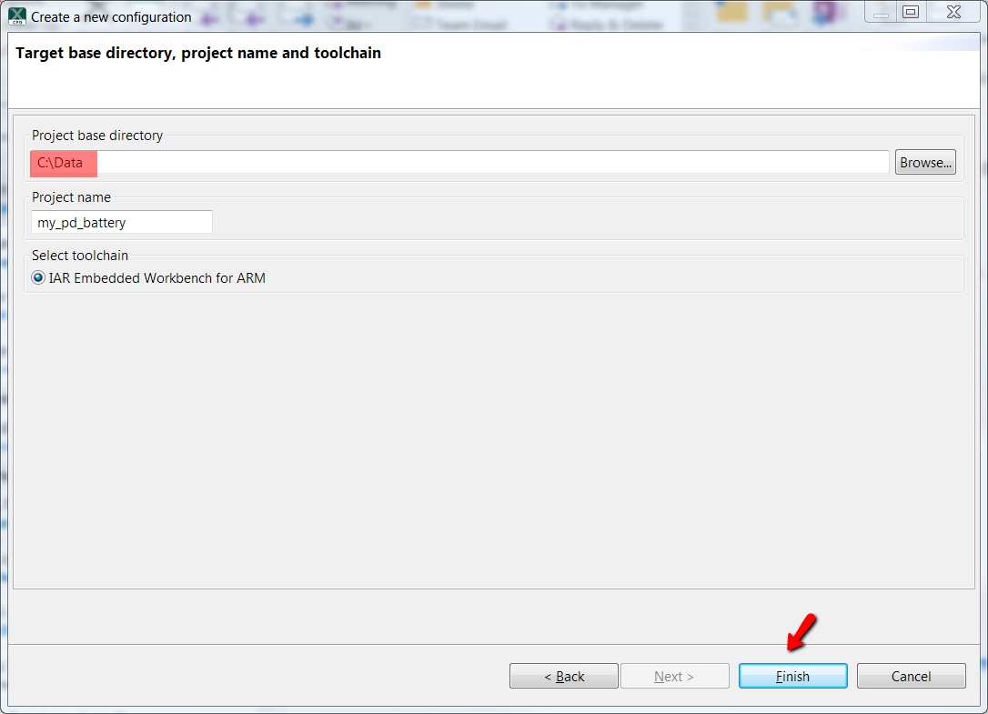
- Choose one of the USB PD sample projects to clone. For this example, the following instructions show how to clone the usb_pd_battery project. Write battery in the filter box and then select the
usb_pd_battery/freertosproject. Then click Next - Then select the directory you want to place the cloned project, give it a name, and choose the IDE to use. Note that the toolchains listed are the same used in the SDK builder. Then click on Finish
- After cloning go to the select directory, and open the project for your IDE. Import, compile, and run the project as done in previous sections
Tera Term Tutorial
Tera Term Tutorial
Tera Term is a very popular open source terminal emulation application. This program can be used to display information sent from your Freescale development platform's virtual serial port.
- Download Tera Term from SourceForge. After the download, run the installer and then return to this webpage to continue
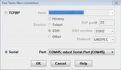
- Launch Tera Term. The first time it launches, it will show you the following dialog. Select the serial option. Assuming your board is plugged in, there should be a COM port automatically populated in the list
- Configure the serial port settings (using the COM port number identified earlier) to
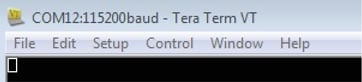
115200baud rate, 8 data bits, no parity, and 1 stop bit. To do this, go to Setup → Serial Port and change the settings - Verify that the connection is open. If connected, Tera Term will show something like below in it's title bar
- You're ready to go
Putty Tutorial
Putty Tutorial
PuTTY is a popular terminal emulation application. This program can be used to display information sent from your Freescale development platform's virtual serial port
- Download PuTTY using the button below. After the download, run the installer and then return to this webpage to continue
- Launch PuTTY by either double-clicking on the
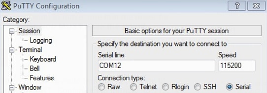
*.exefile you downloaded or from the Start menu, depending on the type of download you selected - Configure In the window that launches, select the Serial radio button and enter the COM port number that you determined earlier. Also enter the baud rate, in this case
115200 - Click Open to open the serial connection. Assuming the board is connected and you entered the correct COM port, the terminal window will open. If the configuration is not correct, PuTTY will alert you
- You're ready to go