Getting Started with EXPI-OS08A20
Contents of this document
-
Out of the Box
-
Hardware Setup
-
Software Setup
Sign in to save your progress. Don't have an account? Create one.
Purchase your EXPI-OS08A20
1. Out of the Box
The following section lists the steps to power on and use the EXPI-OS08A20 camera module.
The development kit contains:
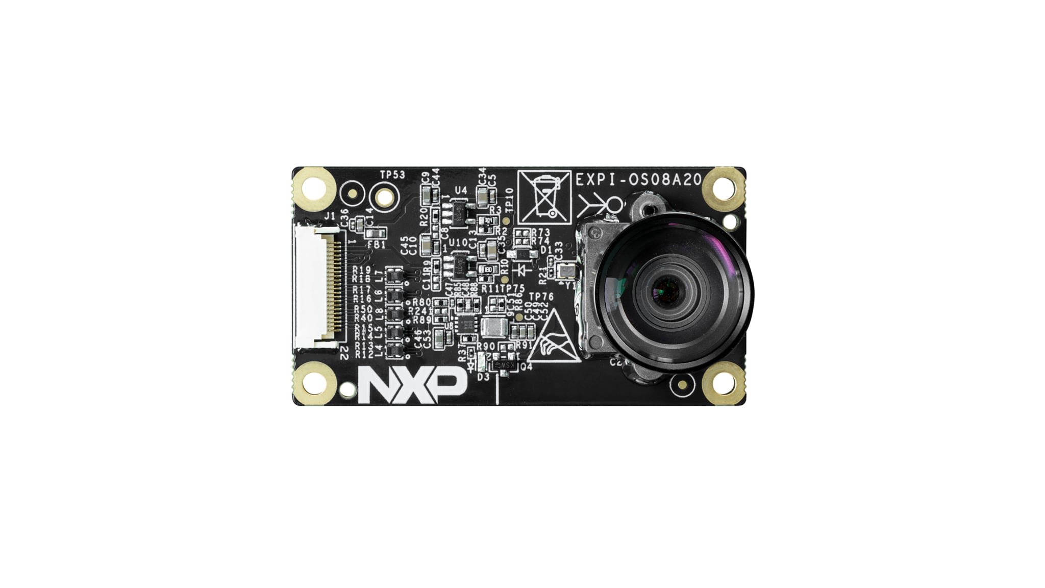
- EXPI-OS08A20 camera module
- Four pairs of white nylon screws and studs
- Assembly manual card
- 180mm, pitch=0.5mm, same-side 22-pin flexible printed circuit (FPC) cable
Get started developing your application on the EXPI-OS08A20 camera module with the out-of-the-box video. For more information, please visit the module webpage.
2. Hardware Setup
This section describes how a connection can be established between the EXPI-OS08A20 camera module and FRDM boards.
2.1 Connect the Camera Module
To setup the hardware connection between EXPI-OS08A20 camera module and FRDM-IMX 8MPLUS, please follow the steps below.
2.3 Boot Switch Setup
SW5 [1:4] is the boot configuration switch. By default, the boot device is embedded MultiMediaCard/Ultra Secured Digital Host Controller 1 (eMMC/uSDHC1).
| BOOT MODE | SW5-1 |
SW5-2 |
SW5-3 |
SW5-4 |
|---|---|---|---|---|
| Serial Downloader | 0 | 0 | 0 | 1 |
| USDHC1 8-bit eMMC 5.1 | 0 | 0 | 1 | 0 |
| USDHC2 4-bit SD3.0 | 0 | 0 | 1 | 1 |
2.4 Connect EXPI-OS08A20 Camera Module
The module supports flexible hardware and software integration, featuring an FPC connector that can be accessed from either side. Two types of FPC cables are available—one with same-side contacts and another with opposite-side contacts. To prevent damage to the camera module, always check the cable orientation before making any connections as reversing the power supply can cause harm.
Follow these steps to assemble the hardware:
- Insert the FPC into the connector
- Secure the circuit board with screws and studs for support
- Connect the other end of the FPC to the FRDM-IMX8MPLUS
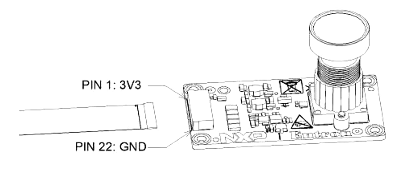
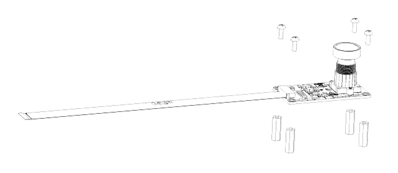
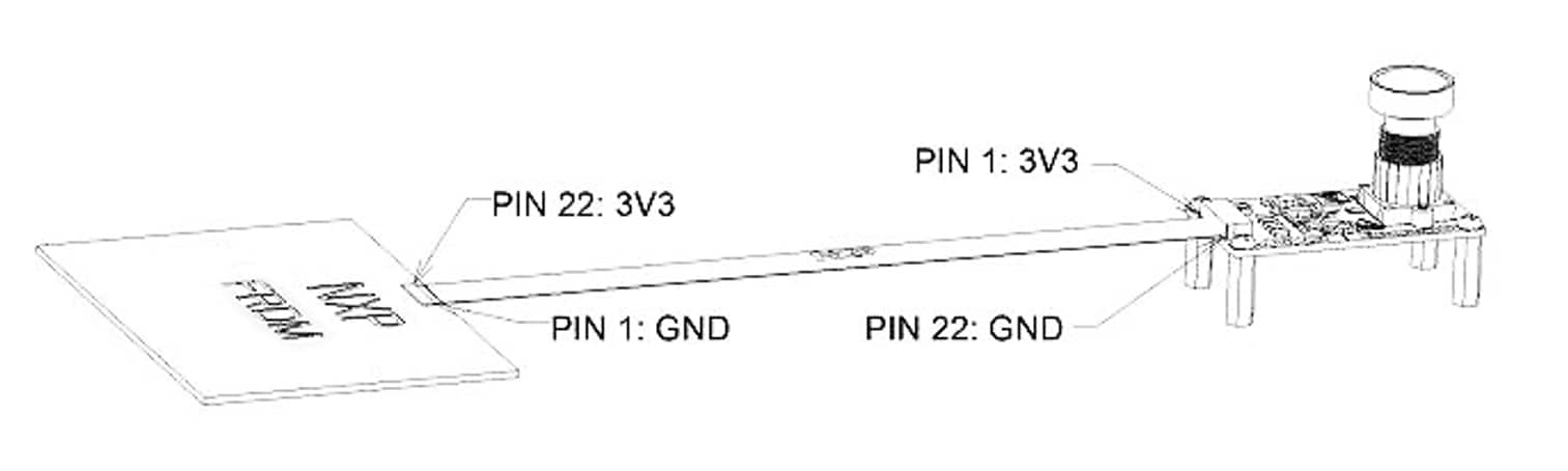
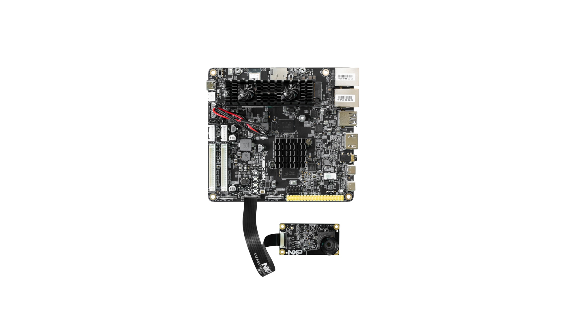
The image below illustrates the connection between the EXPI-OS08A20 camera module and the FRDM-IMX8MP board using the provided FPC cable.
3. Software Setup
This section describes how to set up the software for the EXPI-OS08A20 camera module.
Set Up EXPI-OS08A20 Camera Module on FRDM-IMX8MPLUS Board
To set up the EXPI-OS08A20 camera module, follow the steps below:
3.1 Download a Prebuilt Image
The latest prebuilt images for the FRDM-IMX8MPLUS are available on the FRDM-IMX8MPLUS Demo Images. The image file (with the extension *.wic or *.wic.zst) contains a partitioned image (with U-Boot, kernel, rootfs, and so on) suitable for booting the corresponding hardware.
3.2 Update Prebuilt Image to FRDM-IMX8MP Board
You have options when updating the image depending on the boot source. You can either can use the official universal update utility (UUU) tool or third-party software.
| Boot sources / Flash tools | UUU | Third party flash tool |
|---|---|---|
| eMMC | support | no |
| SD | support | support |
The following steps explain how to boot embedded MultiMediaCard (eMMC) or SD card using the official UUU tool with a prebuilt image. For other methods, please refer to UG10195.
To use the UUU update FRDM-IMX8MPLUS, follow the instructions below:
- Download UUU version 1.2.39 or higher from the GitHub mfgtools releases
- Use a USB Type-C cable to connect your computer to the FRDM-i.MX8M Plus board’s port labeled “USB1_C”
- Connect a USB cable from the USB Type-C connector labeled "DEBUG" to a host computer for debug message outputting
- Set the boot pin to Serial download mode
- Burn the image:
- To update a pre-built image to an SD card, run the following command: uuu -b sd_all imx-boot-imx8mpfrdm.bin imx-image-full-imx8mpfrdm.rootfs.wic
- To update a pre-built image to eMMC, run the following command: uuu -b emmc_all imx-boot-imx8mpfrdm.bin imx-image-full-imx8mpfrdm.rootfs.wic
- To boot the board, change the boot switch to SD/eMMC boot mode and reset the board
For FRDM-IMX8MPLUS, the USB on-the-go (OTG) port is labeled as "USB1_C".
The following table shows the boot switch settings for FRDM-IMX8MPLUS to enter Serial download mode.
| Switch Name | D1 |
D2 |
D3 |
D4 |
|---|---|---|---|---|
SW5 |
0 | 0 | 0 | 1 |
| Switch Name | D1 |
D2 |
D3 |
D4 |
|---|---|---|---|---|
SW5 |
0 | 0 | 1 | 1 |
| Switch Name | D1 |
D2 |
D3 |
D4 |
|---|---|---|---|---|
SW5 |
0 | 0 | 1 | 0 |
3.3 Running EXPI-OS08A20 Camera Module on FRDM-IMX8MPLUS
- To select a device tree, perform the following steps:
- "imx8mp-frdm-os08a20.dtb" - # single os08a20, connect to CSI1
- "imx8mp-frdm-dual-os08a20.dtb" - # dual os08a20, connect to CSI1 and CSI2
- Check to make sure that the subdev and video nodes are correct
- Run Gstreamer to capture and display
u-boot=> setenv fdtfile imx8mp-frdm-os08a20.dtb
    u-boot=> saveenv
    Saving Environment to MMC... Writing to MMC(2)... OK
u-boot=> bootroot@imx8mpfrdm:~# ls /dev
… v4l-subdev0 … video3
… v4l-subdev1 …
… v4l-subdev2 .
… v4l-subdev3
root@imx8mpfrdm:~# cat /sys/class/video4linux/video3/name
viv_v4l20$ gst-launch-1.0 -v v4l2src device=/dev/video3 ! "video/x-
raw,format=YUY2,width=3840,height=2160" ! queue ! waylandsink