Getting Started with FRDM-STBI-NPM8
Contents of this document
-
Out of the Box
-
Kit Contents and Packing List
-
Getting to Know the Hardware
-
Configuring the Hardware
Sign in to save your progress. Don't have an account? Create one.
Purchase your FRDM-STBI-NPM8
1. Out of the Box
1.1 Out of the Box
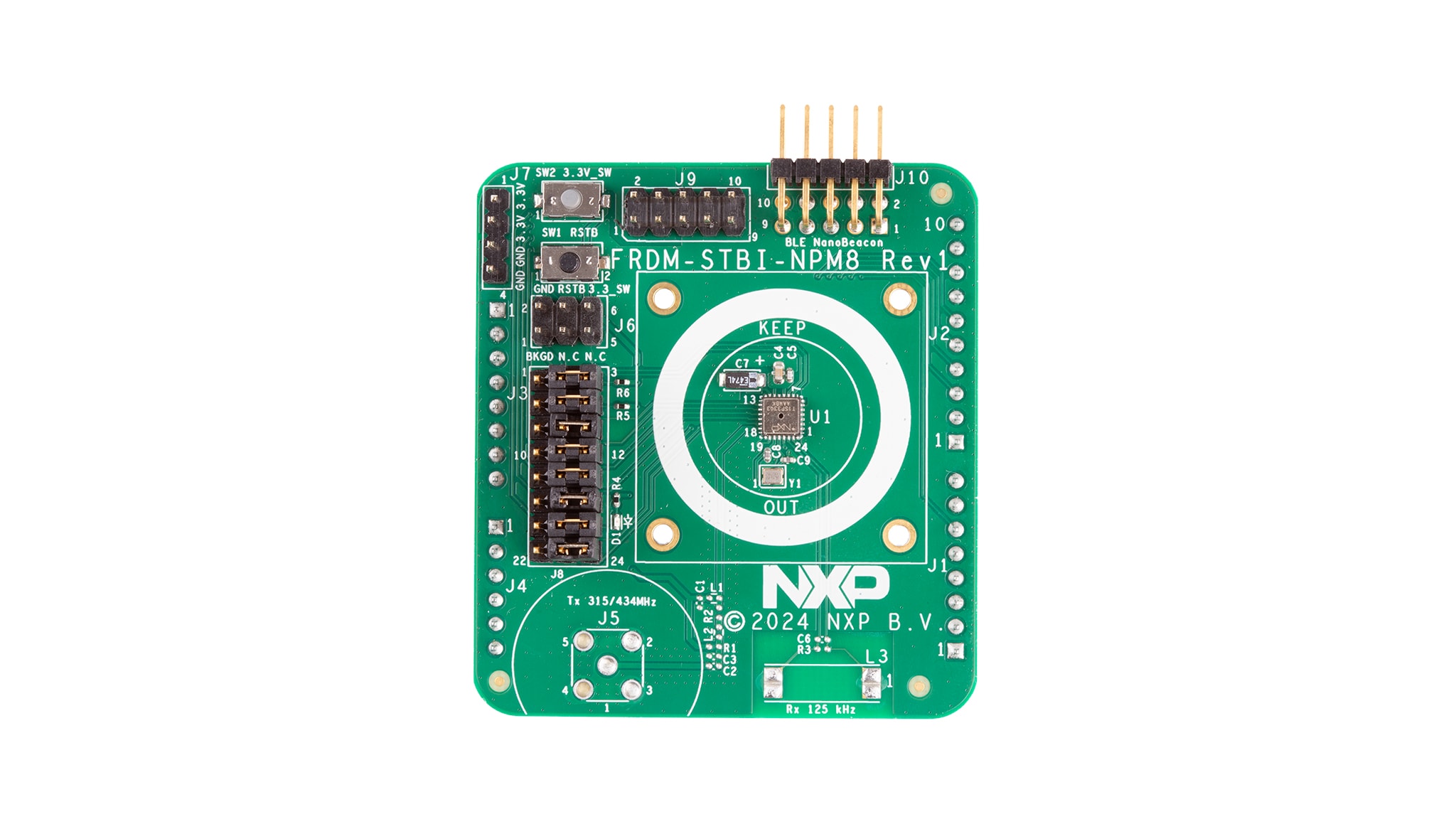
The FRDM-STBI-NPM8 is an evaluation board composed of all necessary headers, jumpers and signal test points to quickly evaluate the NPM8 pressure sensor.
This document is intended to help a user quickly set up, configure, and operate the FRDM-STBI-NPM8 evaluation board.
2. Kit Contents and Packing List
The FRDM-STBI-NPM8 box includes:
- FRDM-STBI-NPM8 shield board compatible with Arduino Uno headers
- 10 x jumpers for hardware configuration
2.1 Extra Hardware
The FRDM-STBI-NPM8 can be paired with a variety of NXP MCU boards, however there is a demo project provided for the FRDM-MCXW71 MCU board for evaluation. More information is provided in Section 3.
3. Getting to Know the Hardware
3.1 Kit Overview
The FRDM-STBI-NPM8 shield board incorporates an NPM8 sensor. The NPM8 is a fully integrated industrial pressure monitoring sensor (IPMS) that includes a programmable 8-bit CPU (S08 family) and enables wired and wireless communication.
The FRDM-STBI-NPM8 shield board can be easily connected to an NXP Freedom MCU board via the Arduino headers for evaluation (see Section 4). The following board is are recommended:
- FRDM-MCXW71
CAUTION
These evaluation boards provide a way to change between profiles and help users in their software development. The FRDM-STBI-NPM8 shield board also contains footprints for low-frequency (LF) reception (125 kHz) and sub-GHz radio frequency (RF) transmission. However, the passive elements related with these sub-Ghz wireless modules:
- Are not populated in this board revision as they are not targeted as main profiles
- Must not be populated in this board revision for this board to maintain EMC compliance with FCC requirements and the EU Radio Equipment Directive
See Schematic, board layout and bill of materials for bill of material (BOM) details and refer to the NPM8 data sheet for more information.
3.2 Shield board features
The NPM8 family comprises fully integrated industrial pressure monitoring sensors (IPMS) with an absolute pressure range of 90 kPa to 1500 kPa. These sensors incorporate a dual-axis accelerometer architecture within a 4 mm × 4 mm × 1.98 mm package, optimized for ultralow power consumption, featuring a typical standby current of 180 nA.
The NPM8Kx4S IPMS integrates an 8-bit microcontroller (MCU) and offers seven GPIOs, a client SPI and a two-channel timer/pulse width modulation (PWM) module, ensuring system control and communication.
Features include:
- Absolute pressure ranges: 90 kPa to 1500 kPa
- Transducer measurement interfaces with low-power AFE:
- 10-bit compensated pressure sense element
- 8-bit compensated internal device temperature measurement
- 8-bit compensated internal device voltage measurement
- 8-bit S08 compact instruction set controller:
- 64 bytes low power always-on nonvolatile memory (NVM) parameter registers
- 512-bytes SRAM
- 16 kB flash memory (512 bytes reserved for NXP coefficients)
- Native wireless two-way communication:
- Radio frequency transmission at 315 MHz or 434 MHz
- Data reception at 125 kHz
- Wired communication:
- Client SPI supporting host access to internal peripherals, registers and memory
- Host SPI and controller I2C enabled via software drivers
- Small package: 4 mm x 4 mm x 1.98 mm. QFN, 24 pins, 0.5 mm pitch
- Target applications: Air compressors, air tools, rachet wrench, paint sprayers
- Low power consumption, allowing to supply the sensor from a coincell battery
- Temperature range: -40 °C to 125 °C
- Qualified in compliance with NXP Standard Industrial Mission Profile
3.3 Shield board featured components
Figure 1 identifies important components on the board.
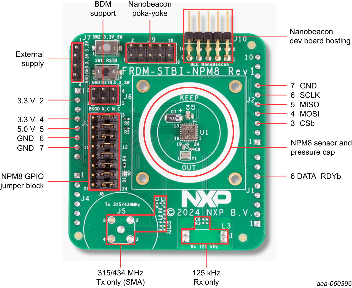
The FRDM-STBI-NPM8 shield board comes with standard Arduino Uno headers and can be paired with NXP Freedom MCU boards for user evaluation and software development. For evaluation and prototyping, NXP provides a demo project targeted to the FRDM-MCXW71 board and the hardware design files.
3.4 BDM Support
The standard 2x3 header pin arrangement, see Figure 1, is provided for typical background Debug mode (BDM) interface cables. A normally open momentary pushbutton switch is provided to assert RSTb low. A normally closed momentary pushbutton switch is provided to interrupt power to the NPM8 (part of BDM access).
3.5 FRDM-STBI-NPM8 Hardware Design Files
The FRDM-STBI-NPM8 shield board design files can be found and downloaded from the NPM8 product page under the Tools and Software tab.
4. Configuring the Hardware
4.1 Configuring the Hardware
Figure 2 shows the typical hardware configuration incorporating the FRDM-STBI-NPM8 evaluation board with standard Arduino headers combined with the FRDM-MCXW71 MCU board. See Table 1 for a description of the hardware configuration.
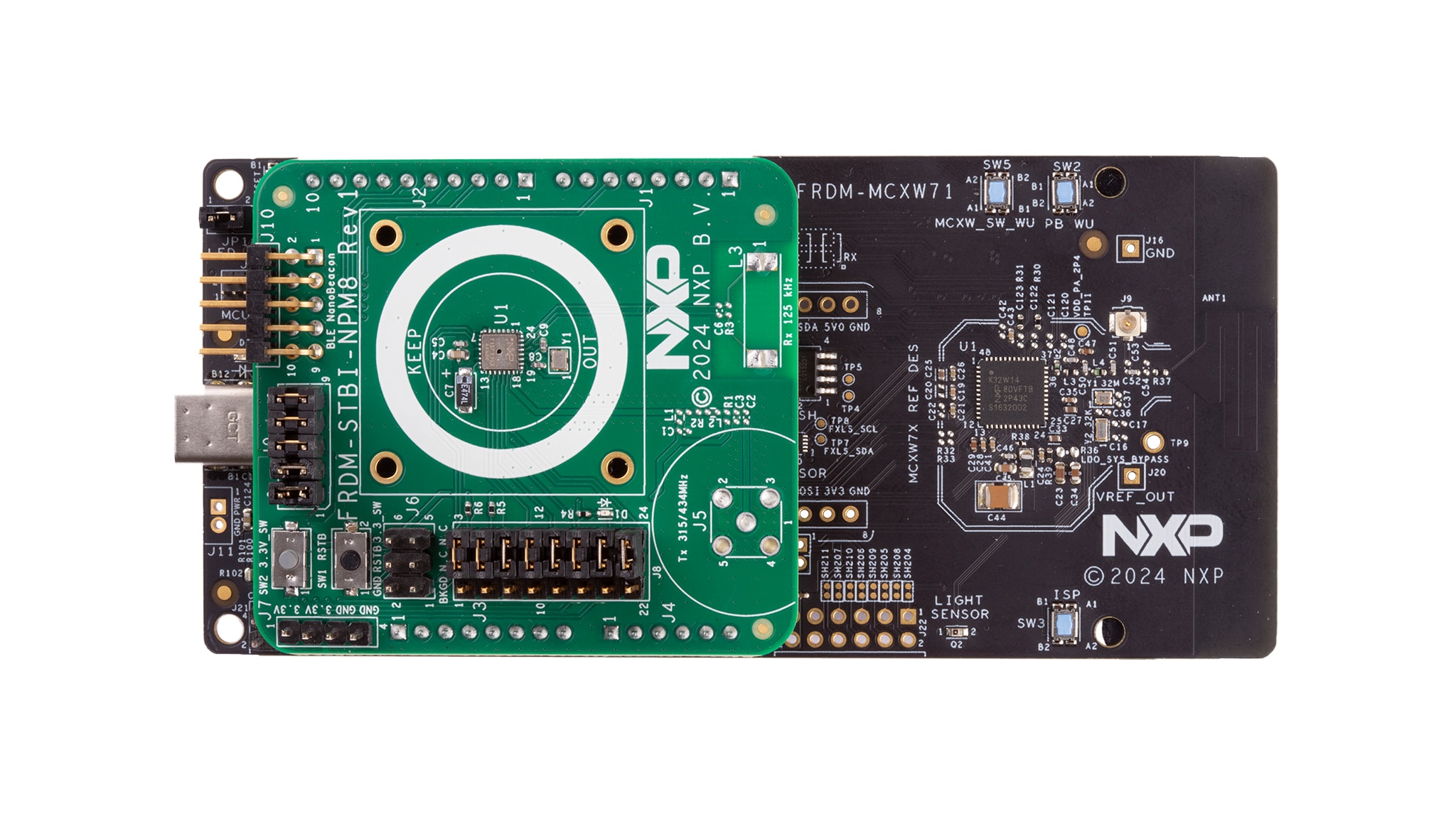
Figure 3 the FRDM-STBI-NPM8 in its standalone configuration, functioning as a host for the IN100 Bluetooth Low Energy Nano Beacon. The IN100 operates in codeless mode, eliminating the need for firmware development and allowing users to quickly configure and deploy Bluetooth Low Energy applications. See Table 2 for a description of the hardware configuration.
NXP provides software (SW) packages to support the evaluation of both configurations: demo projects designed for the FRDM-MCXW71 and the NanoBeacon IN100 (Standalone mode). These SW package demos can be accessed on the NPM8 webpage.
Design Resources
Board Information
In addition to the NPM8 Freedom Shield evaluation board for NPM8 Industrial Pressure Monitoring Sensor page, visit: