Getting Started with MTRCKTSPS5744P
Contents of this document
-
Plug It In
-
Get Software
-
Build And Run
-
Debug and Control
Sign in to save your progress. Don't have an account? Create one.
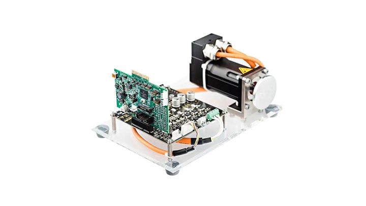
Purchase your MPC5744P 3-phase PMSM Development Kit
1. Plug It In
Choose between watching a short setup video or following the step-by-step guide.
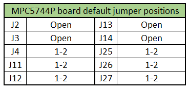
1.1 Configure the MPC5744P Controller Board
Ensure jumpers are in their default position:
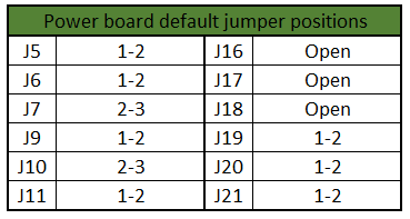
1.2 Configure the 3-phase Low-Voltage Power Stage Board
Ensure jumpers are in their default position:
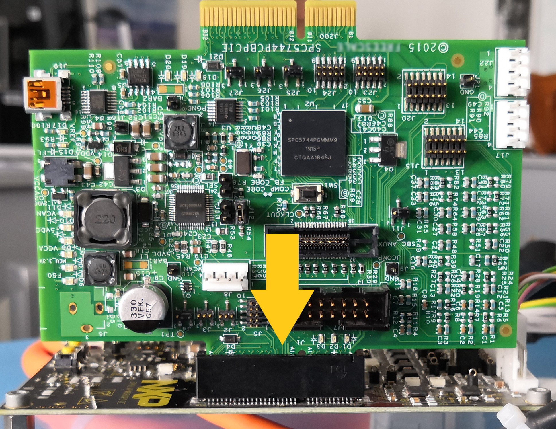
1.3 Plug the MPC5744P Into the Power Board
Use PCIe connector (J1 → J14) to connect MPC5744P board with the Power board.
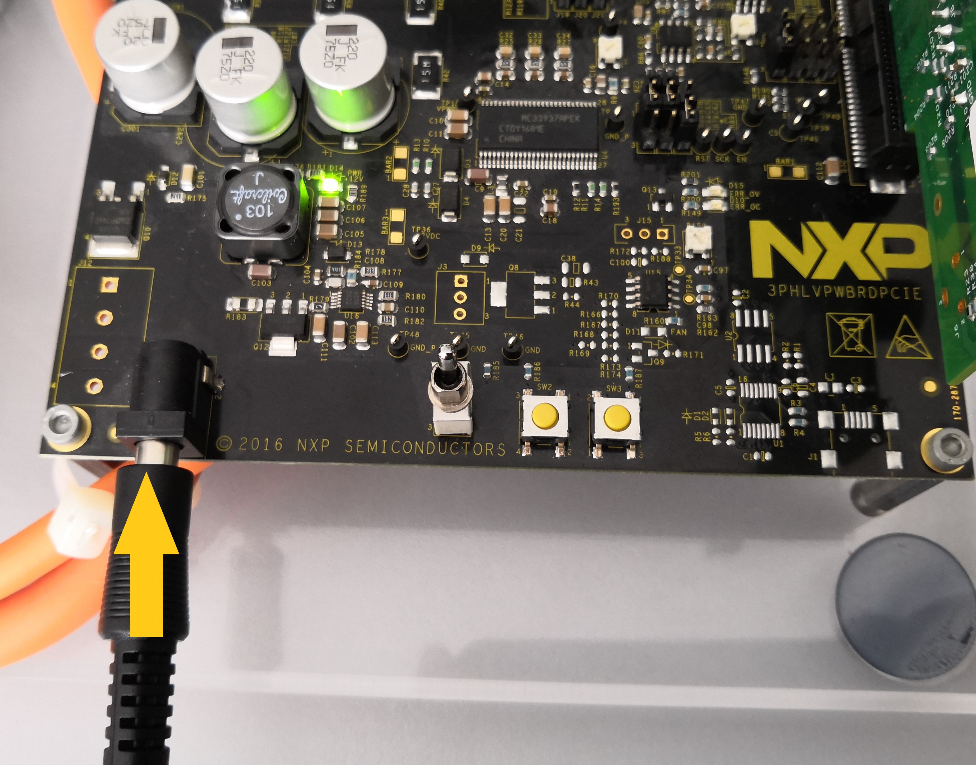
1.4 Plug the 24 V Power Supply
Attach the 24 V power supply for powering the MPC5744P controller and the 3-phase Low-Voltage Power Stage boards together with the 3-phase PMSM motor
2. Get Software
2.1 Download the Motor Control Application Software
Download the complete motor control application software for MTRCKTSPS5744P and the latest version of the Automotive Math and Motor Control Library Set.
2.2 Get Your Integrated Development Environment (IDE)
MTRCKTSPS5744P performs better using S32 Design Studio IDE for Power Architecture®
2.3 Get Your Debugger
MTRCKTSPS5744P performs better using FreeMASTER Run-Time Debugging Tool 2.0
2.4 Get Your Port Driver
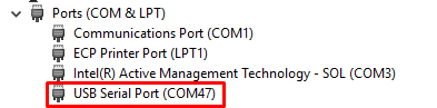
Select the virtual COM port (VCP) driver based on your operating system and processor architecture. Run “Device Manager” on your system and determine which COM port was assigned to the FTDI COM port driver.
Select the virtual COM port (VCP) driver based on your operating system and processor architecture. Run “Device Manager” on your system and determine which COM port was assigned to the FTDI COM port driver.
3. Build And Run
3.1 Import the Software Project Into Your IDE
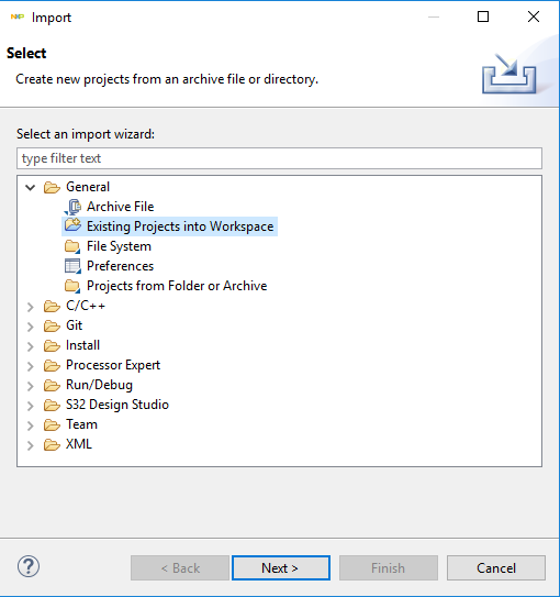
Import the installed application software project in the S32 Design Studio for Power Architecture® by launching S32 Design Studio and then click File - Import and then select General - Existing Projects into Workspace.
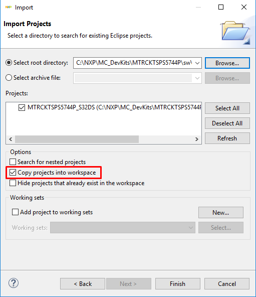
Navigate to the installed application directory MC_DevKits\ MTRCKTSPS5744P\sw\FreeMASTER_control and click OK, then Finish.
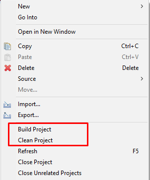
3.2 OPTIONAL - Build Project
These steps should not be necessary since they are executed in the next step automatically:
- Right click on the imported project and select Clean
- Right click on the imported project and select Build
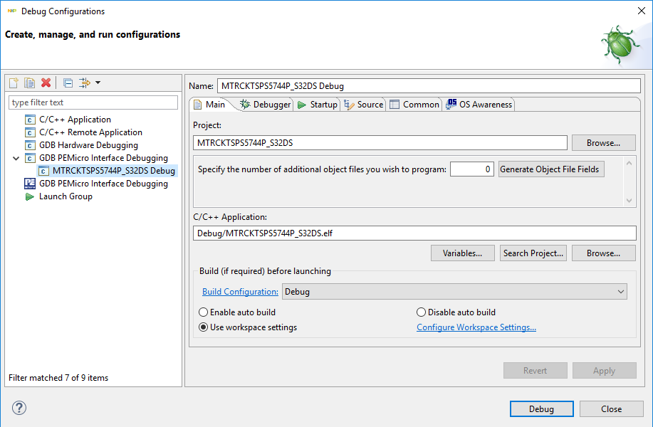
3.3 Debug for Loading Code Into S32K144 MCU
In the S32 Design Studio menu click Run - Debug Configuration and select the predefined debug configuration and click on Debug to start loading built code into MCU.
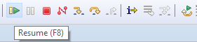
3.4 Let Code Run and Disconnect
Let code run by click on Resume (F8) button.
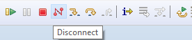
Use the Disconnect button for avoiding interference between S32DS debugger and FreeMASTER tool.
4. Debug and Control
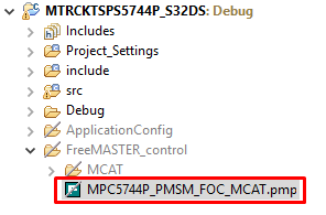
4.1 Start FreeMASTER Project
Start the FreeMASTER project for debugging by launching FreeMASTER and then open <your workspace>\MTRCKTSPS5744P_S32DS\FreeMASTER_control\MTRCKTSPS5744P_PMSM_FOC-MCAT.pmp by clicking File - Open Project…
4.2 Create a Connection With MCU
Select Options from the Project menu, and choose the RS232 COM port number that was assigned to the virtual COM port driver and set the communication speed to 115200 Bd.
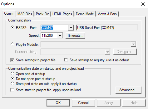
Click the red STOP button in the FreeMASTER toolbar (or press <CTRL> + <K>) to enable the communication
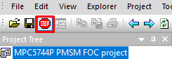
Successful communication is signalized in the status bar at very bottom as:
RS232 UART Communication;COMn; speed = 115200
4.3 Open App Control Page
Click App Control tab in the Motor Control Application Tuning tool (MCAT) tool menu to display the application control page. Configure the motor rpms and turn on the motor drive.
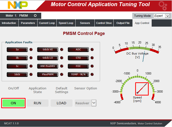
Success! Motor runs.
On this page
- 1.1
Configure the MPC5744P Controller Board
- 1.2
Configure the 3-phase Low-Voltage Power Stage Board
- 1.3
Plug the MPC5744P Into the Power Board
- 1.4
Plug the 24 V Power Supply
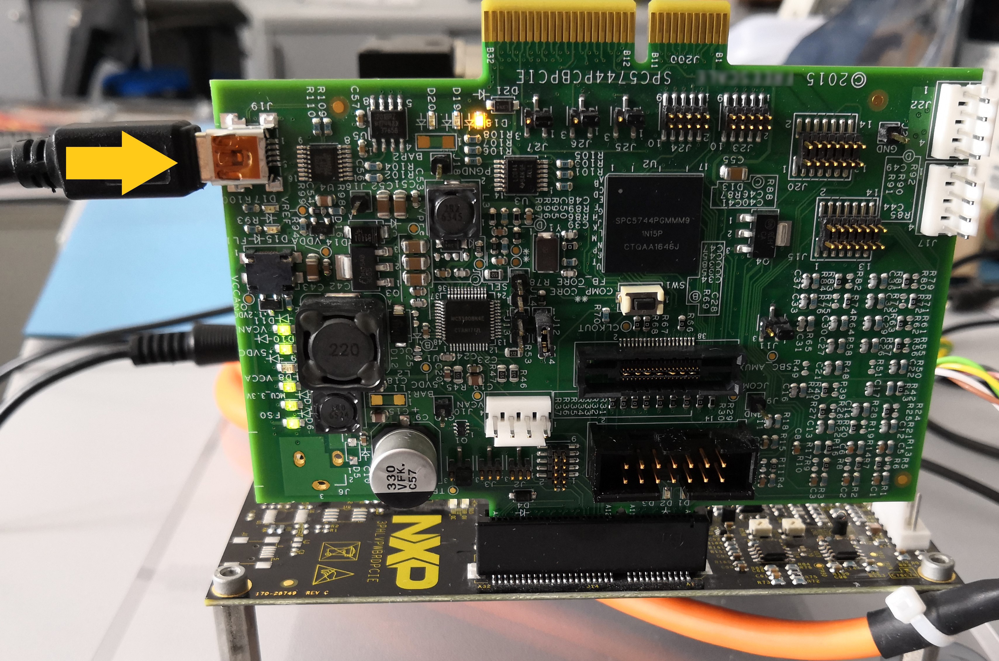
- 1.5
Plug the USB Cable
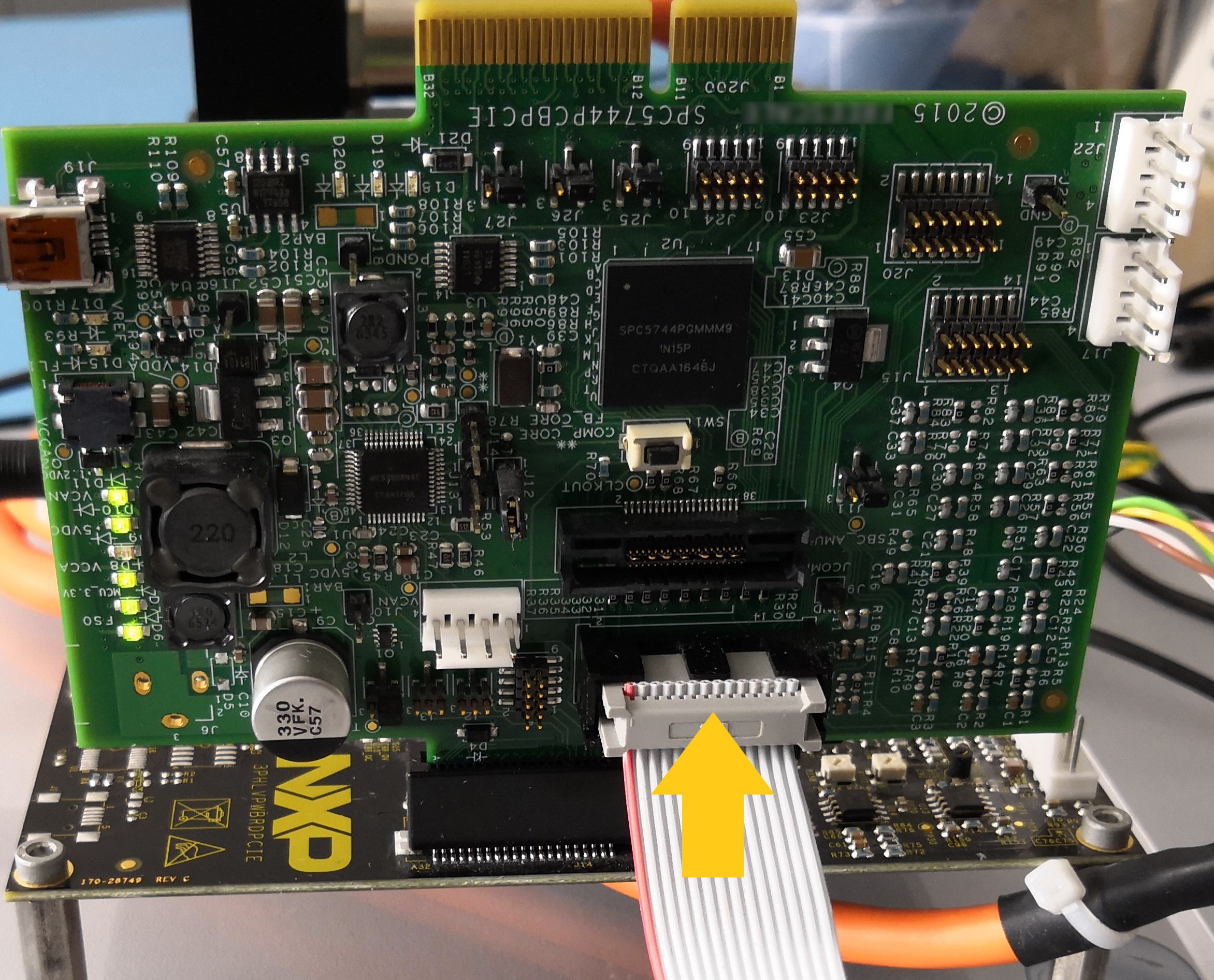
- 1.6
Plug the JTAG/NEXUS Cable
- 2.1
Download the Motor Control Application Software
- 2.2
Get Your Integrated Development Environment (IDE)
- 2.3
Get Your Debugger
- 2.4
Get Your Port Driver