Getting Started with the EasyEVSE EV Charging Signal Boards
Contents of this document
-
Out of the Box
-
Plug It In
-
Get Software
-
Build and Run
Sign in to save your progress. Don't have an account? Create one.
Purchase your EasyEVSE EV Charging Signal Board
1. Out of the Box
The NXP EasyEVSE EV Charging Signal Boards are an add-on board for several EV charging development platforms. This get started helps you to get the board up and running which integrates with an NXP host platform evaluation board. The main host of the system is on a separate processor development board. For EVSE simulation, the host platform board can be a i.MX 8 or 9 applications processor boards (MIMX93-EVK or FRDM-IMX93) or a i.MX RT crossover MCU board (MIMXRT1060/1064-EVK).
For EV simulation the host platform can be a i.MX 8 or 9 applications processor boards (MIMX93-EVK or FRDM-IMX93), a i.MX RT crossover MCU board (MIMXRT1060/1064-EVK), a S32G automotive processor board (S32G-VNP-RDB3) or a S32K3 MCU board (S32K3X4EVB-T172).
Use the EVSE-SIG-BRD2X as an add-on board to demonstrate basic charging and high-level communication (ISO 15118) by sending data signals between an EV and EVSE host controller board. The EVSE-SIG-BRD2X board is compatible with EasyEVSE MPU‑based and MCU‑based development platforms.
Use the SIGBRD-HPGP as an add-on board to support high-level communication (ISO 15118) between the EV and EVSE. By using the SIGBRD-HPGP together with the EVSE-EMETER on the EVSE side, the EasyEVSE development platform (with either an MPU or MCU host controller) enables precise acquisition of electrical parameters. The platform can measure the grid voltage supplied to the EV with high accuracy, as well as continuously monitor charging current and compute the total energy transferred throughout the charging session.
1.1 Kit Contents for EVSE-SIG-BRD2X
The NXP EasyEVSE EV Charging Signal Board kit contains the following:
- 1 x EVSE-SIG-BRD2X
- 1 x 100 - 240 V AC - 5 V DC (15 W) Power Supply
- 1 x GPIO connector-cable to connect to MCIMX93-EVK evaluation boards
- 1 x GPIO connector-cable to connect to S32G-VNP-RDB3 boards
1.2 Kit Contents for SIGBRD-HPGP
The miscellaneous hardware and tools required to program the board is shown below:
- 1 x MCU-Link Debug Probe or MCU-Link Debug Probe
- 1 x SIGBRD-HPGP
- 1 x 100 - 240 V AC - 5 V DC (15 W) Power Supply
1.3 Required Hardware
Get the required hardware and miscellaneous hardware and tools.
When using the EVSE-SIG-BRD2X board:
- 1 x Windows, Linux or MAC personal computer to build the EVSE-SIG-BRD MCUXpresso SDK source code project using NXP MCUXpresso IDE
- 1 x EVSE-IMX93_CBL when using the MCIMX93-EVK as a host (1 x cable kit includes the EV and EVSE side)
- 1 x EVSE-RT106X-CBL when using the MIMXRT1060-EVKB or MIMXRT1064-EVK as a host (1 x cable kit includes the EV and EVSE side)
- 1 x coaxial cable to connect the EVSE-SIG-BRD2X EasyEVSE EV Charging Signal boards between the EVSE and EV side
When using the SIGBRD-HPGP board:
- 1 x Windows, Linux or MAC personal computer to build the EVSE-SIG-BRD MCUXpresso SDK source code project using NXP MCUXpresso IDE
- 1 x coaxial cable to connect the SIGBRD-HPGP boards between the EVSE and EV side
- 4 x wires to connect the EVSE-EMETER and SIGBRD-HPGP through UART
- 2 x wires to connect the EVSE-EMETER and SIGBRD-HPGP for CP and GND
1.4 Miscellaneous Hardware and Tools
The miscellaneous hardware and tools required to program the board is shown below:
- 1 x MCU-Link Debug Probe or MCU-Link Debug Probe
2. Plug It In
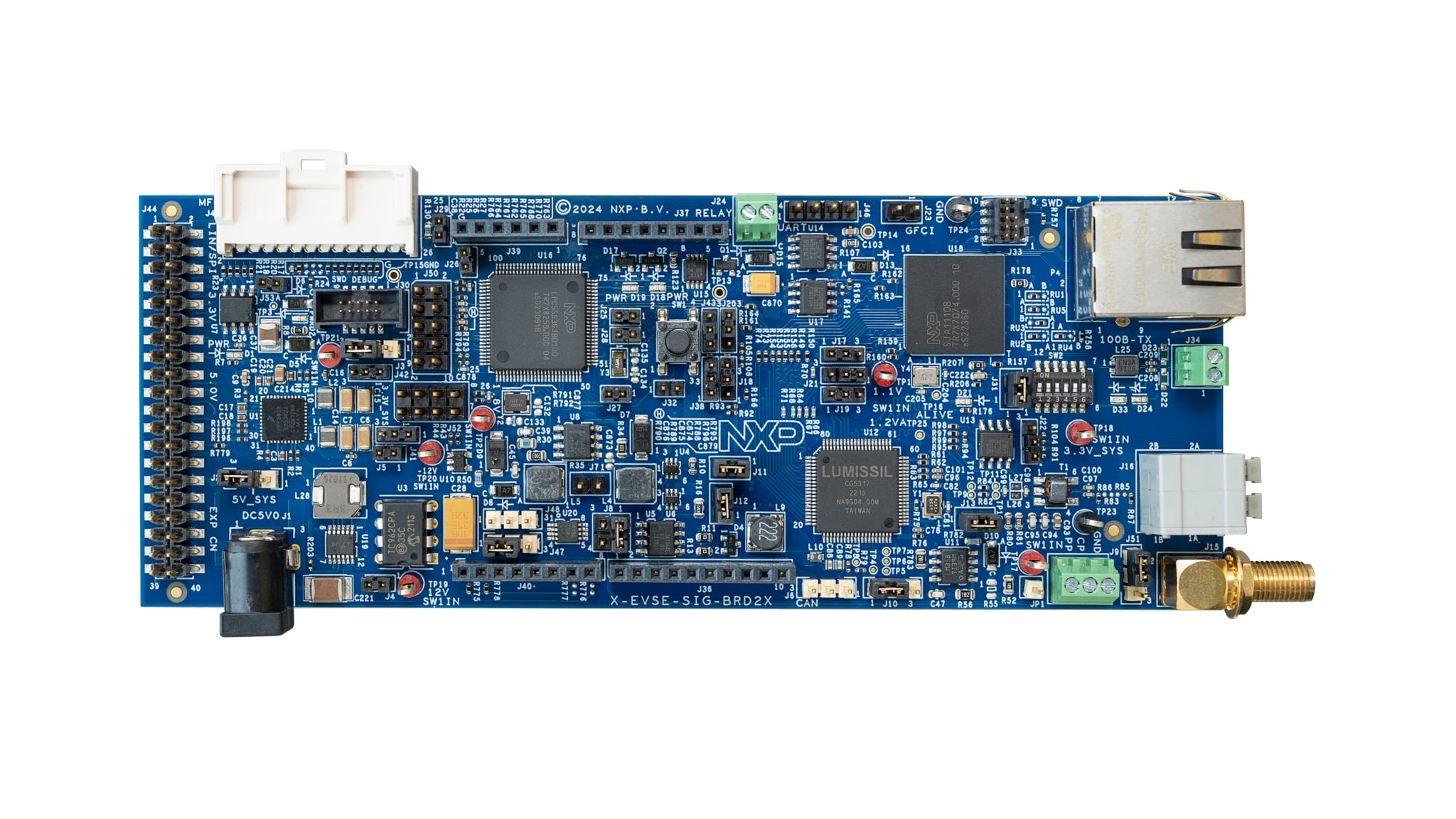
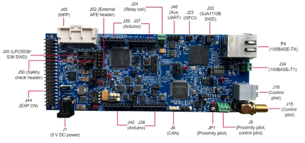
2.1 Get Familiar with the Board
The NXP EVSE-SIG-BRD2X takes the power from the host EVK connectors, for example, Arduino, EXP-CN, or MFP connector. To drive external relays (140 mA or above generated at 12 V), the board has a DC power jack for supplying 5 V external power. The kit comes with an 5 V DC power supply. For using additional power supplies, please refer to the User Guide.
The NXP SIGBRD-HPGP takes the power from the host EVK connectors, for example, Arduino, EXP-CN, or MFP connector. Within the board, it generates a +12 V supply by using a boost converter. The +12 V supply is used for the CP PWM signaling. Alternatively, a 5 V power can be provided externally through power jack input, P1. For using additional power supplies, please refer to the User Manual.
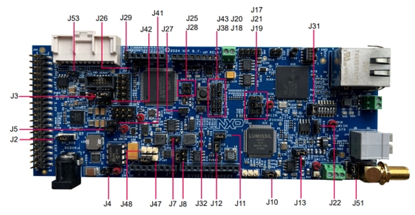
2.2 Hardware and Jumper Requirements for EVSE-SIG-BRD2X
| Part identifier | Jumper type/default | Description |
|---|---|---|
J2
|
1x3-pin header |
5V_SYS power source selection jumper:
|
J3
|
1x3-pin header |
3.3V_SYS power source selection jumper:
|
J4
|
1x2-pin header |
12V0_ISO supply enable jumper:
|
J5
|
1x2-pin header |
-12V0_ISO supply enable jumper:
|
J7
|
1x2-pin header |
EVSE/EV PWM loopback enable jumper:
|
J8
|
2x2-pin header |
Control pilot selection jumper:
|
J10
|
1x3-pin header |
Proximity pilot board test points:
|
J11
|
1x2-pin header |
3V3_CG5317 supply enable jumper:
Open: 3V3_CG5317 supply is OFF Shorted (default setting): 3V3_CG5317 supply is produced from 3.3V_SYS supply |
J12
|
1x2-pin header |
VCORE supply enable jumper:
|
J13
|
1x2-pin header |
3.3 VA supply enable jumper:
|
J17
|
1x3-pin header |
|
J18
|
|
|
J19
|
|
|
J20
|
|
|
J21
|
|
|
J22
|
|
|
J25
|
1x2-pin header |
MCU_VDD supply enable jumper:
|
2.3 Hardware and Jumper Requirements for SIGBRD-HPGP
| Power Source | Manufacturing part number | Power supply rail | Description |
|---|---|---|---|
Through J3 Pins10,16, J23 Pins2,4 and J26 Pins1 |
- | 5V_ARD_EXP_CN | Power supply received from host board with Arduino, ECP CN or Multi-Function Port(S32G-VNP-RDB2) |
Through Barrel Connector P1 |
- | DC_5V_IN | Power supply received through external 5 V DC power source |
Through J25 Pin2 |
- | 5V_SYS | Board 5 V power. Can be selected either from 5V_ARD_EXP_CN, DC_5V_IN or supplied from external power source |
Through J3 Pins4,8, J23 Pins1,17 and J26 Pin3 |
- | 3V3_ARD_EXP_CN | Power supply received from host board with Arduino, ECP CN or Multi-Function Port(S32G-VNP-RDB2) |
U15 |
PPF5020CMMAYES | VDD_3V3 | 3.3 V output from PMIC |
Through J28 Pin2 |
- | 3.3V_SYS | Board 3.3 V power. Can be selected either from 3V3_ARD_EXP_CN, VDD_3V3 or supplied from external power source |
U15 |
PPF5020CMMAYES | VCC_1V1 | 1.1 V output from PMIC. Power supply for SJA1110 switch core |
U2 |
AP3012KTR-G1 | 12V0 | Board 12 V power. Powers Control Pilot |
3. Get Software
The NXP EVSE-SIG-BRD2X and SIGBRD-HPGP application software for the EVSE and EV run as bare metal environment on the LPC55s36 microcontroller (for EVSE-SIG-BRD2X) or MCX A (SIGBRD-HPGP). For the EVSE-SIG-BRD2X and SIGBRD-HPGP two separate software are used for the EVSE and EV side of the board usage and can be downloaded via the provided software zip files on the main NXP EasyEVSE EV Charging Signal Board design page. One Windows, Linux or MAC PC is required to build the LPC55S36 or MCX A software.
3.1 NXP EVSE-SIG-BRD2X and SIGBRD-HPGP Firmware
To program the signal board, the following software requirements needs to be downloaded and installed:
- MCUXpresso IDE (Used for EVSE-SIG-BRD2X and SIGBRD-HPGP board. Download and install the IDE based on your operating system on your PC. For further help, please refer to the user guides for EVSE-SIG-BRD2X or SIGBRD-HPGP)
- LPC5536 SDK (Used for EVSE-SIG-BRD2X board. Download and install the LPCXpresso55S36 SDK v 2.14.0 to compile version V1 of the EVSE-SIG-BRD2X projects. For further help, please refer to the user guide)
- MCXA154 SDK (Used for SIGBRD-HPGP. Download and install the MCUXA154 SDK. To build the SIGBRD-HPGP sample project, SDK_2.x_MCXA154 is required. For further help, please refer to the user guide)
3.2 Downloading and Installing MCUXpresso IDE
MCUXpresso IDE is a free-of-charge, code-size-unlimited, and easy-to-use IDE for Kinetis, LPC and MCX MCUs and i.MX RT crossover processors.
To install MCUXpresso IDE, perform the following steps:
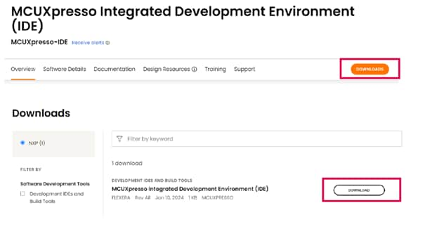
-
Go to the MCUXpresso-IDE and click the
Download button
- Sign in to your account at the NXP website. If you do not have an account, click CREATE AN ACCOUNT

- If you are an existing user, click Employee Sign In and enter your email address or NXP ID, and password.

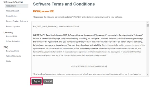
- Click MCUXpresso IDE
- Accept the software terms and conditions
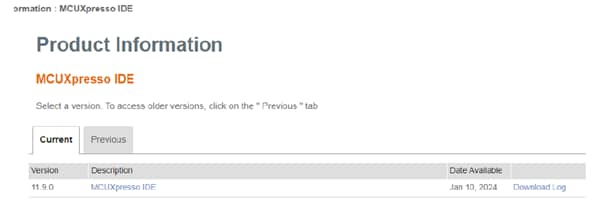
- Select the MCUXpresso product version.
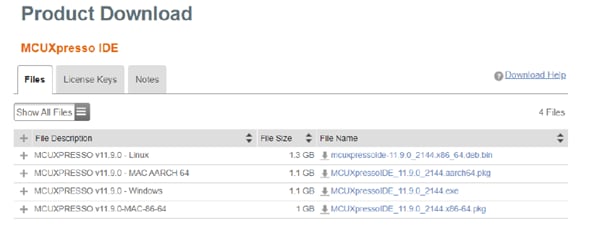
- To start the download, click the corresponding File Name
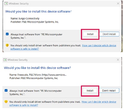
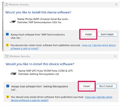
- Double-click the installer file and follow the setup wizard until the MCUXpresso IDE installation is
completed. Allow the installation of the additional drivers required by the MCUXpresso IDE during the
installation process
3.3 Downloading and Installing LPC5536/LPC55S36 SDK and MCX A SDK
The following steps and illustrations show the setup processes for LPC5536-EVK, which can be used to as the SDK for LPC5536/LPC55S36 based EVSE-SIG-BRD2X.
-
Install and import the LPCXpresso55S36 SDK as follows:
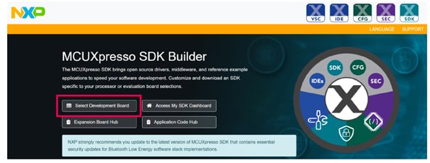
- Browse to MCUXpresso SDK Builder and click Select Development Board
- Sign in with your NXP account. If you do not have one yet, click Register Now, enter your credentials and click Sign-in.
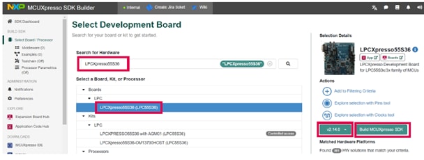
- Enter the name of the LPCXpresso55S36 board under Search for Hardware
- Select the required board from the drop-down list and select the recommended SDK release version
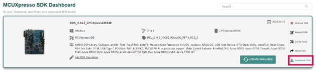
- Click Build MCUXpresso SDK
- When building the SDK, specify the Host OS, and specify "MCUXpresso IDE" as the Toolchain. For simplicity reasons, select all the available middleware and click Download SDK
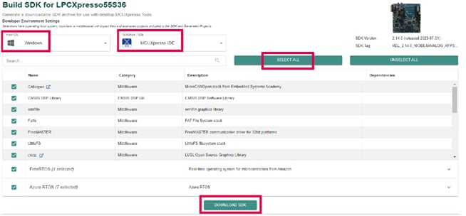
- When the build completes, download the SDK archive (9) and agree to the software terms and conditions
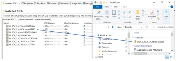
- Open the MCUXpresso IDE in your desired workspace
- Drag and drop the SDK into the Installed SDKs window of the IDE
The following steps and illustrations show the setup processes for the MCUXA154 SDK for the SIGBRD-HPGP board.
- Install and import MCXA154 SDK. Browse to the MCUXpresso SDK Builder and click "Select Development Board". You will be asked to sign in with your NXP account. If you do not have one yet, click Register Now, type your credentials in the fields, and click "Sign in":
- In the drop-down list, click on Processors, then choose MCX, then MCXA and select MCXA154. On the right side of the page, click on ARMGCC button
- When building the SDK, specify your OS and MCUXpresso as the toolchain. For simplicity reasons, select all the available middleware and click "BUILD SDK". 4 When the building completes, download the SDK archive
- Image
- Open the MCUXpresso IDE in your desired workspace and drag and drop the SDK into the "Installed SDKs" window of the IDE
4. Build and Run
4.1 Build and Run
After installing MCUXpresso and downloading the LPC5536 SDK or MCXA154 SDK to your PC, ensure to import and program the corresponding project variant for the EVSE-SIG-BRD2X or SIGBRD-HPGP board for EVSE and EV simulations. For details on how to import the sample projects, refer to the user guide for the EVSE-SIG-BRD2X or SIGBRD-HPGP board. The software files for each board and for EVSE or EV application, can be found on the main EasyEVSE EV Charging Signal Board design page under the section Software.
To build the EVSE simulation software, perform the following steps in MCUXpresso (applicable for EVSE-SIG-BRD2X and SIGBRD-HPGP board):
- Click Import project(s) from the file system... from the Quickstart Panel of MCUXpresso IDE
- Select the related file which you have downloaded from GitHub and import the EVSE simulation project
- Click the Finish button
- Click the hammer button on the top-left side of the IDE and start building the project. The build is done without errors
- Click the beetle button on the top-left side of the IDE and start programming the board with the project binary. Once the programming is completed, it breaks at a breakpoint at the main() function of the code
- To resume the operation, click the play button
To build the EV simulation software, perform the following steps (applicable for EVSE-SIG-BRD2X and SIGBRD-HPGP board):
- Click Import project(s) from the file system... from the Quickstart Panel of MCUXpresso IDE
- Select the related file which you have downloaded from GitHub and import the EV simulation project
- Click the Finish button
- Click the hammer button on the top-left side of the IDE and start building the project. The build is done without errors
- Click the beetle button on the top-left side of the IDE and start programming the board with the project binary. Once the programming is completed, it breaks at a breakpoint at the main() function of the code
- To resume the operation, click the play button
Design Resources
On this page
- 1.1
Kit Contents for EVSE-SIG-BRD2X
- 1.2
Kit Contents for SIGBRD-HPGP
- 1.3
Required Hardware
- 1.4
Miscellaneous Hardware and Tools
- 2.1
Get Familiar with the Board
- 2.2
Hardware and Jumper Requirements for EVSE-SIG-BRD2X
- 2.3
Hardware and Jumper Requirements for SIGBRD-HPGP