Getting Started with the EV-INVERTERGEN3 EV Traction Inverter Control Reference Design Gen 3
Contents of this document
-
Out of the Box
-
Get Software
-
Plug It In
-
Build, Run and Load
-
Application Control
Sign in to save your progress. Don't have an account? Create one.
Purchase your EV-INVERTERGEN3
1. Out of the Box
NXP's EV Traction Inverter Gen 3 SiC MOSFET Enablement Kit is designed for customers using SiC MOSFETs modules to develop the traction inverter module that controls electric vehicle traction motors.
This page will guide you through the process of setting up and using the EV Traction Inverter Control Reference Design Gen 3 (EV-INVERTERGEN3).
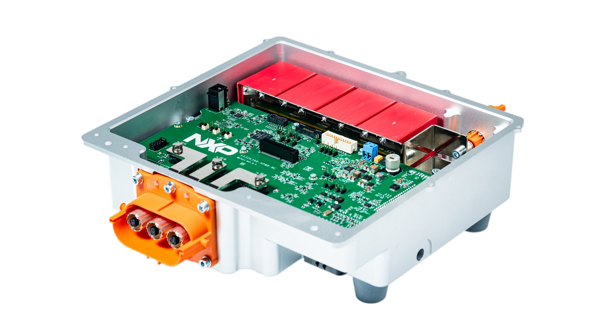
1.1 EV-INVERTERGEN3 Overview
EV Traction Inverter Control Reference Design Gen 3.
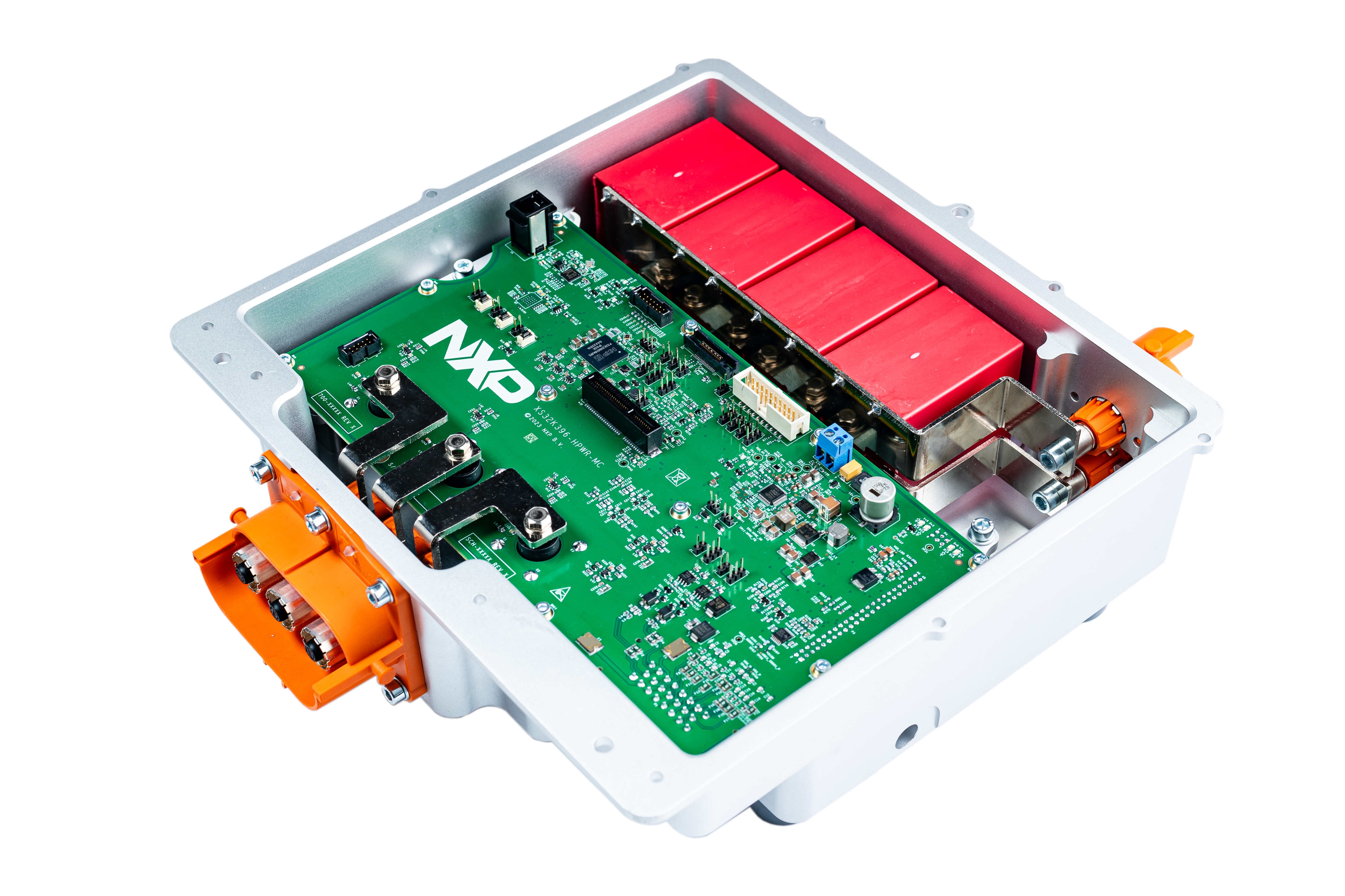
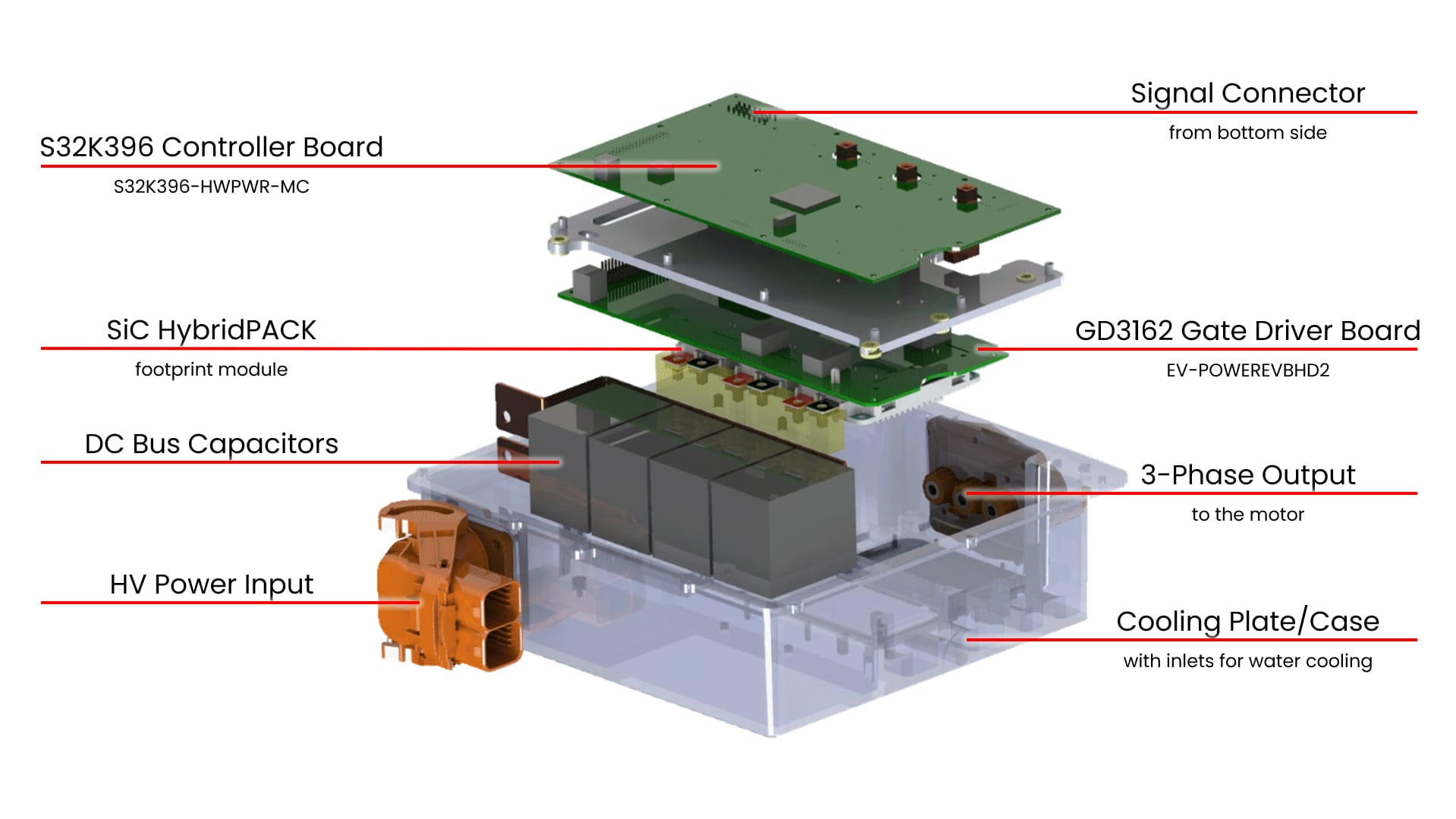
The EV-INVERTERGEN3 kit includes:
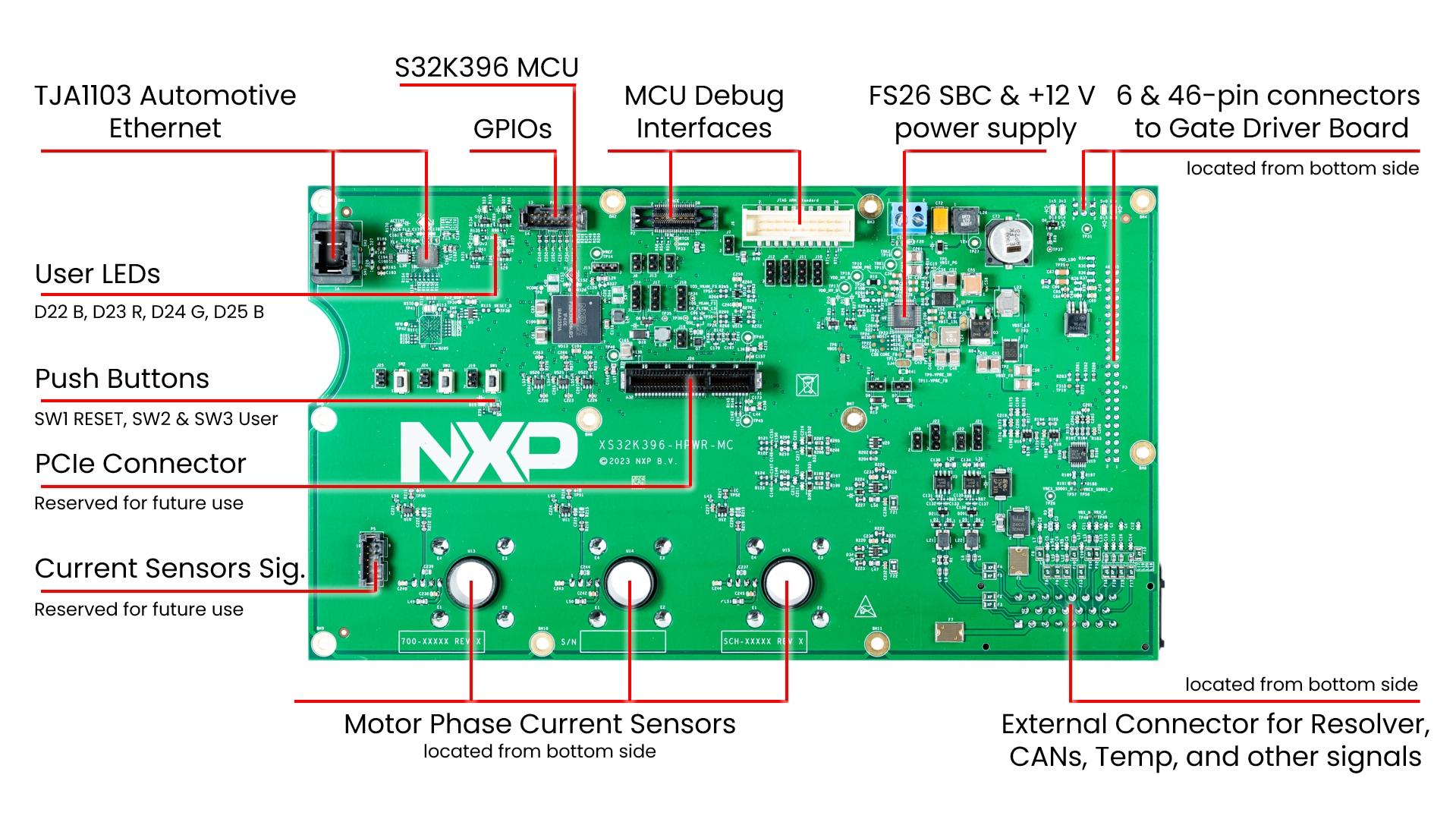
- MCU control board (S32K396-HPWR-MC)
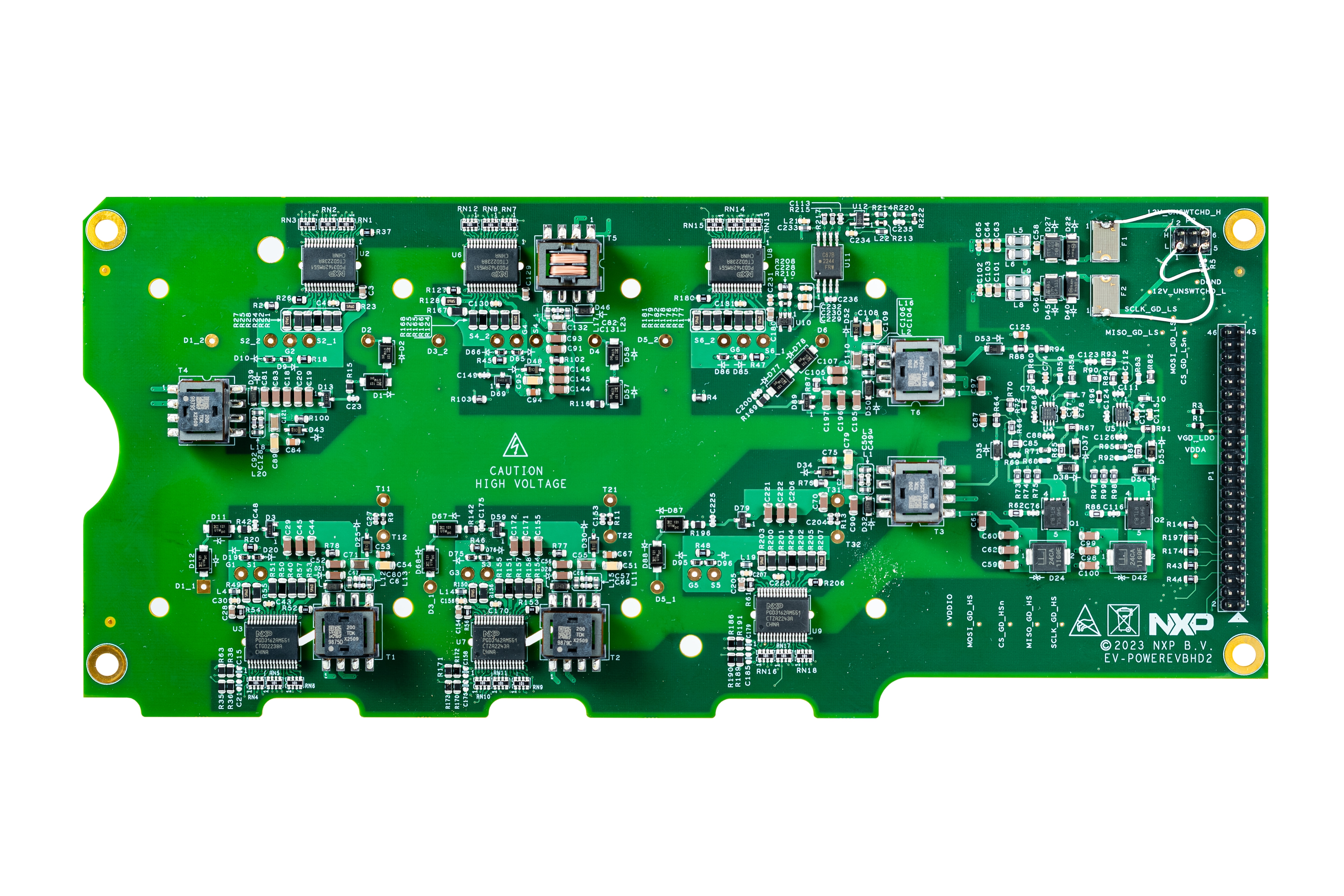
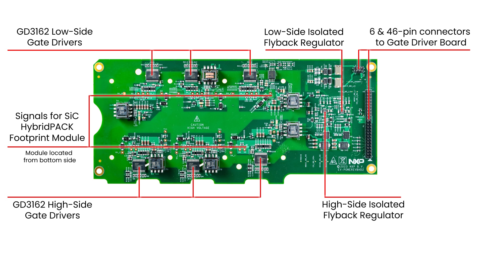
- Driver control board (EV-POWEREVBHD2)
- 3-phase output busbars for Hall-effect current sensors
- 6-pin and 46-pin header connectors for interfacing between S32K396-HPWR-MC and EV-POWEREVBHD2 boards
To build the EV Traction Inverter Control Reference Design Gen 3, you will need additional hardware beyond what is contained in the EV-INVERTERGEN3 kit. The NXP partner Vepco may provide these components, or you may build your own traction inverter setup:
- SiC HybridPACK footprint module
- Cooling plate or water jacket compatible for SiC HybridPACK footprint module
- Busbar between the DC link capacitors and SiC MOSFET module
- DC link capacitor
- Optional 23-position signal connector AMPSEAL (PN 770680-1)
- Optional high-voltage shielded cable (2-wire) from signal connector to the motor resolver excitation
- Optional low-voltage shielded cable (21-wire) from signal connector to the motor resolver sense signals, CAN, signals, ...
- Optional 46-pin flat ribbon cable to connect the S32K396-HPWR-MC MCU control board to the EV-POWEREVBHD2 driver control board
- Optional board stand-offs for mechanical support for the components
For the development of a traction inverter you will need these tools and components:
- 12 V low-voltage DC power supply
- High-voltage DC power supply, for example, an 800 VDC (or similar) for the motor
- USB-CAN interface, for example, a PCAN-USB
- Arm Compatible JTAG debug interface, for example, a PEmicro Multilink debug probe
- A 3-phase permanent magnet synchronous (PMSM) motor
- High-voltage cables (2-wire) for power input
- High-voltage cables (3-wire) for motor
- Low-voltage cables for powering the MCU control board from the 12 V DC power supply

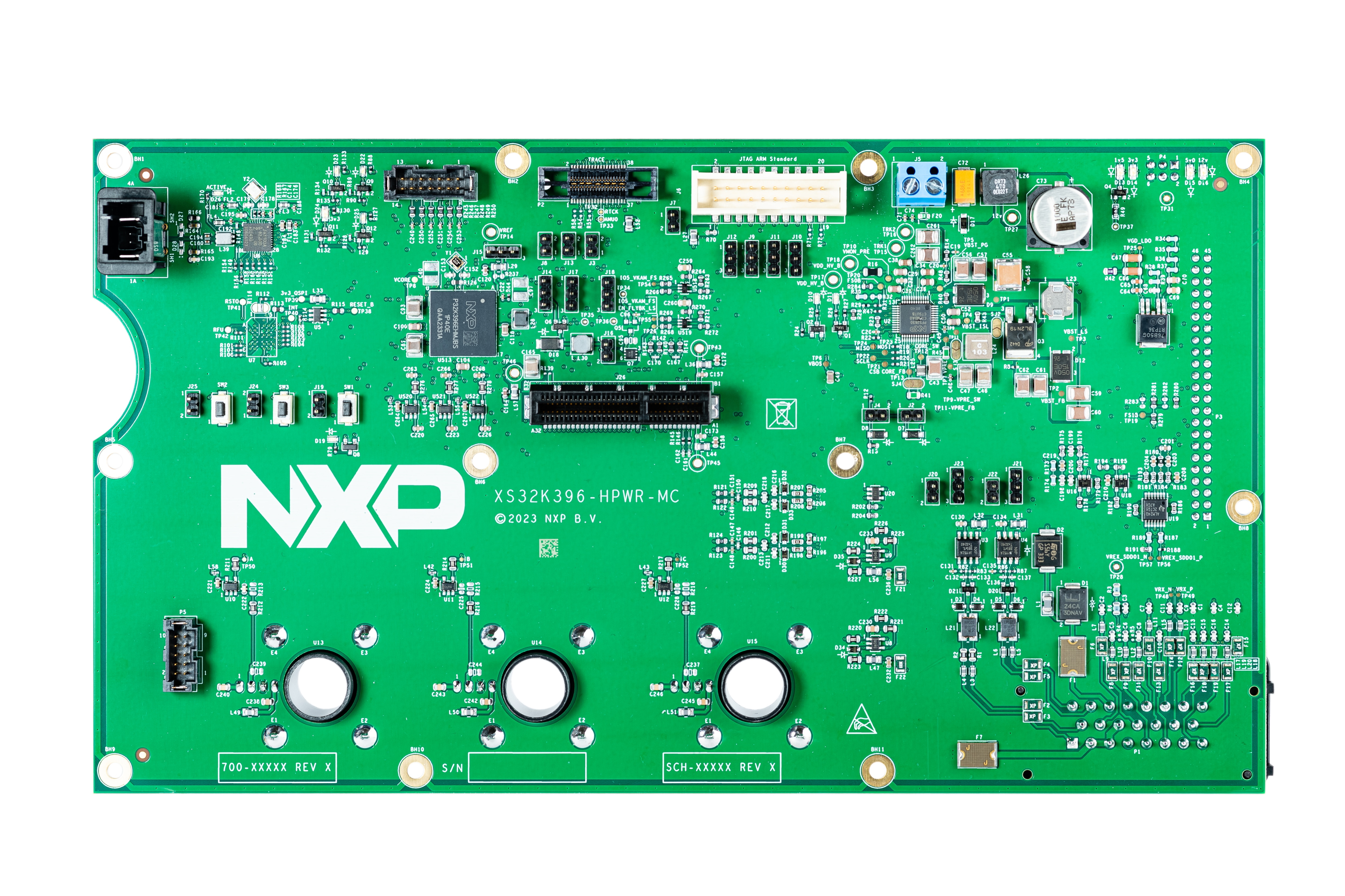
1.2 S32K396-HPWR-MC Features
S32K396-HPWR-MC MCU Control Board.
2. Get Software
Sign in at nxp.com with your credentials.
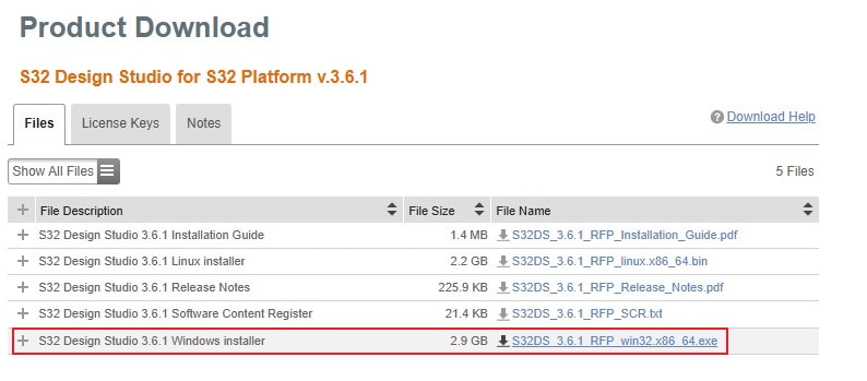
2.1 Get S32 Design Studio
Download and Install S32 Design Studio for S32 Platform.
Download S32 Design Studio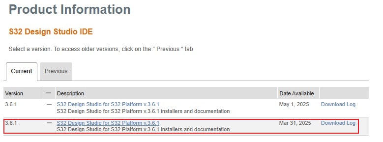
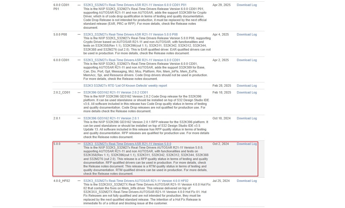
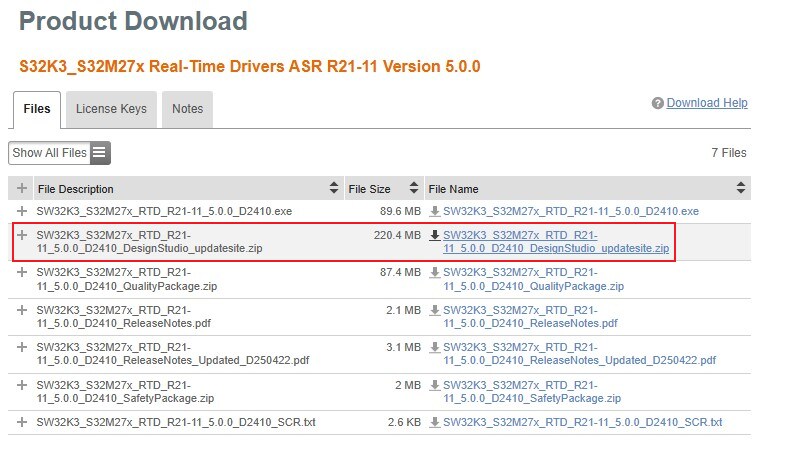
2.2 Downloading the Real-Time Drivers
Download S32K3_S32M27x Real-Time Drivers ASR R21-11 Version 5.0.0

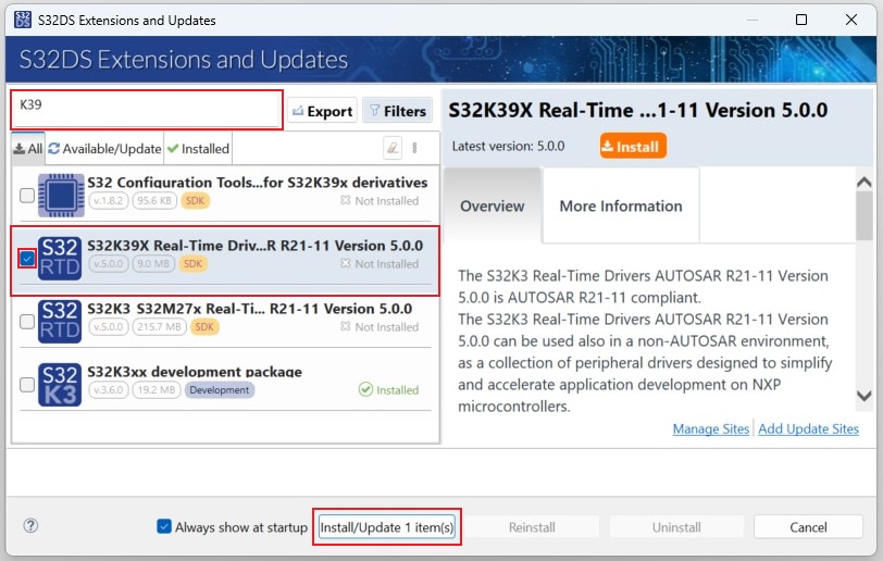
2.3 Install the RTD Drivers
In S32DS, go to Help → S32DS Extensions and Updates from the top menu to open the S32DS Extensions and Updates dialogue.
Click on Add Update Sites and browse for the downloaded RTD *.zip file.
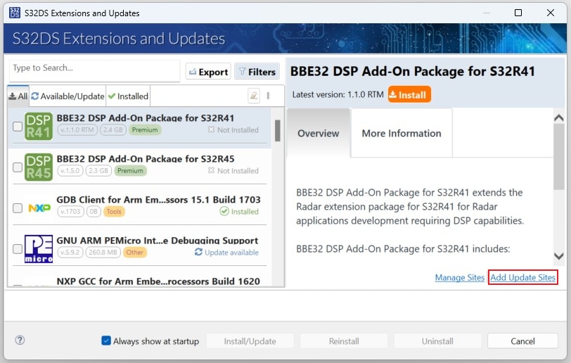
Find, select and install S32K39X Real-Time Drivers ASR R21-11 Version 5.0.0.
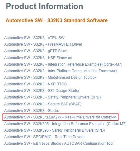
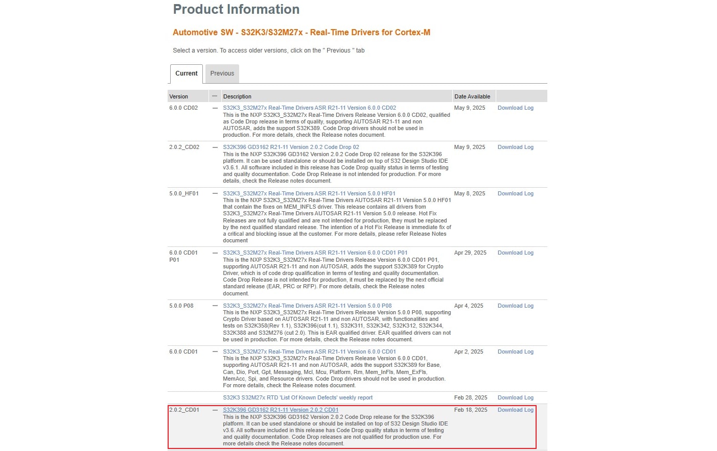
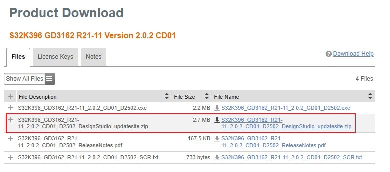
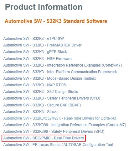
2.4 Download GD3162 Driver
Download S32K396 GD3162
R21-11 Version 2.0.2 CD01 driver from
Automotive SW - S32K3/S32M27x - Real-Time Drivers for Cortex-M package.
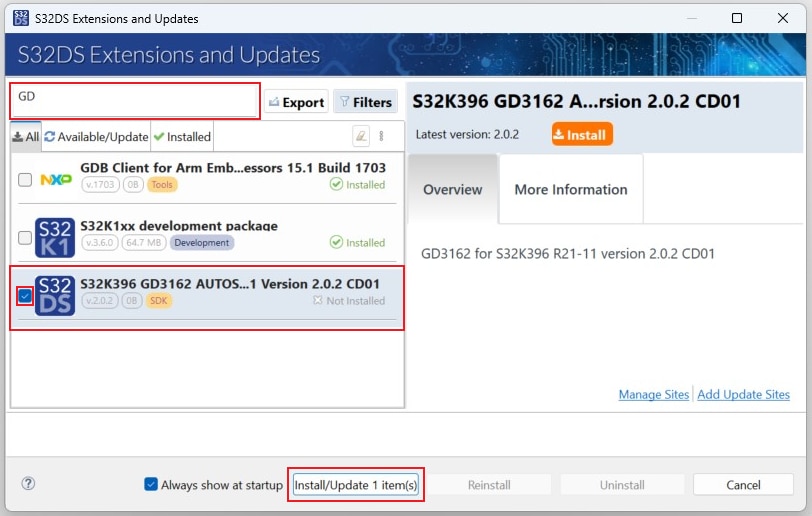
2.5 Install GD3162 Driver
In S32DS, go to Help → S32DS Extensions and Updates from the top menu to open the S32DS Extensions and Updates dialogue.
Click on Add Update Sites and browse for the downloaded GD3162 update site file.
 Select and install GD3162 drivers.
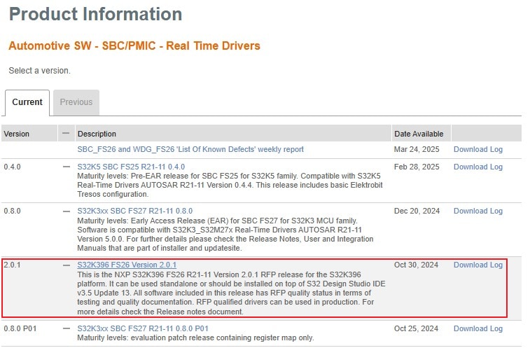
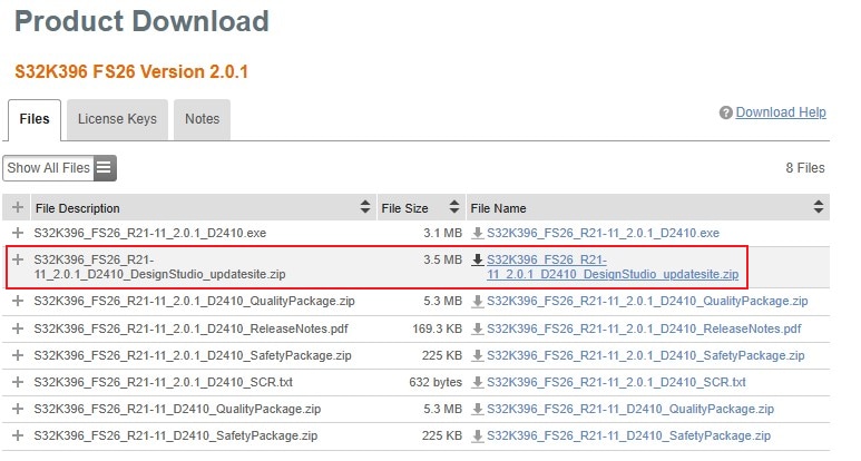
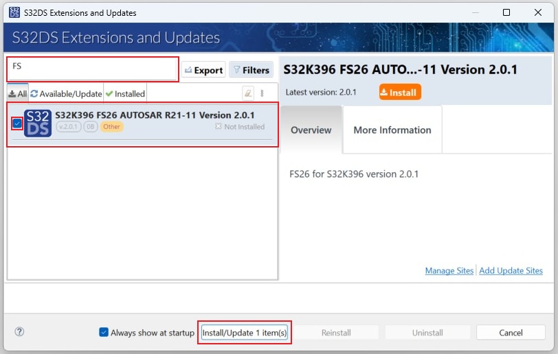
2.7 Install FS26 Driver
In S32DS, go to Help → S32DS Extensions and Updates from the top menu to open the S32DS Extensions and Updates dialogue.
Click on Add Update Sites and browse for the downloaded S32K396 FS26 Driver update site file.

Select and install FS26 drivers.
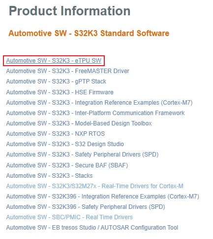
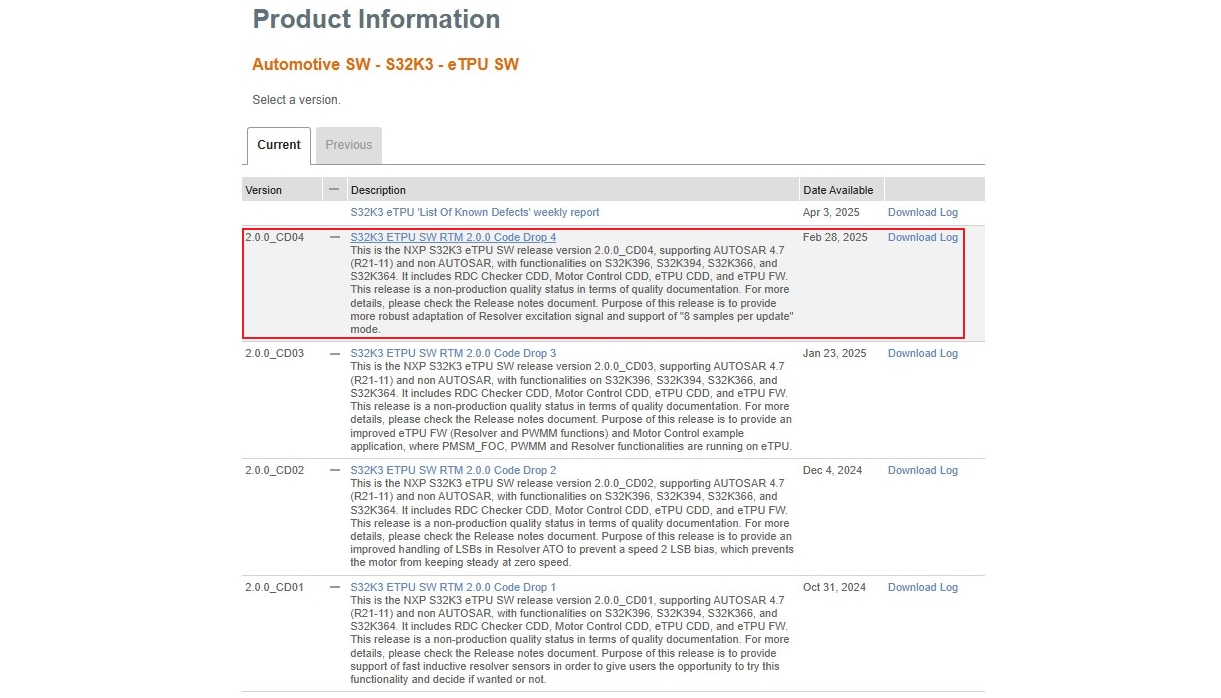
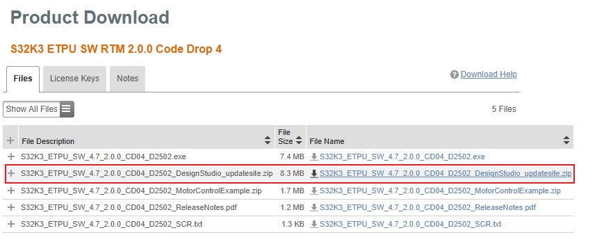
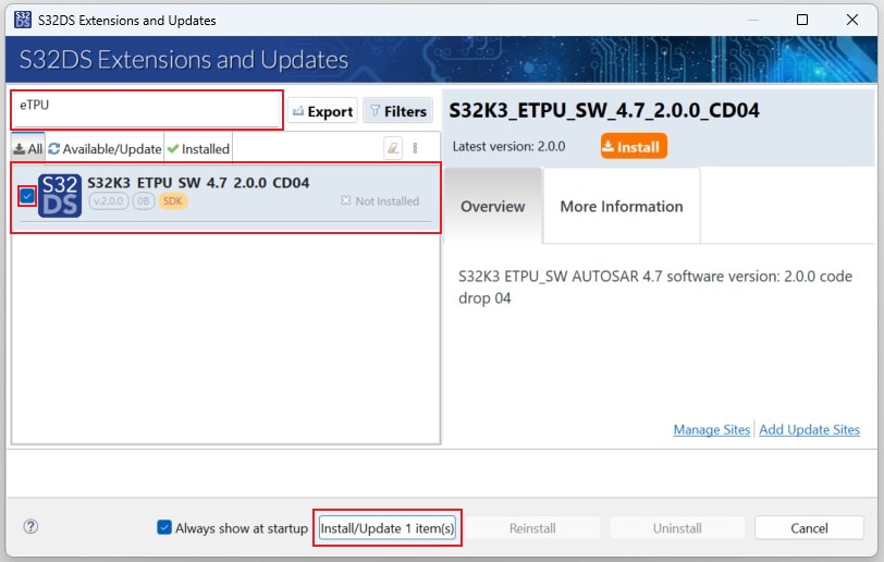
2.9 Install eTPU SW
In S32DS, go to Help → S32DS Extensions and Updates from the top menu to open the S32DS Extensions and Updates dialogue.
Click on Add Update Sites and browse for downloaded eTPU SW update site file.

Select and install eTPU SW.
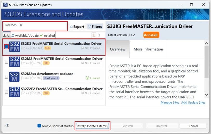
2.10 Get FreeMASTER Comm. Driver
In S32DS, go to Help → S32DS Extensions and Updates from the top menu to open the S32DS Extensions and Updates dialogue.
Select and install the S32K3 FreeMASTER Communication driver.
2.11 Get FreeMASTER Application Tool
Download and install FreeMASTER tool 3.2 for real-time debugging.
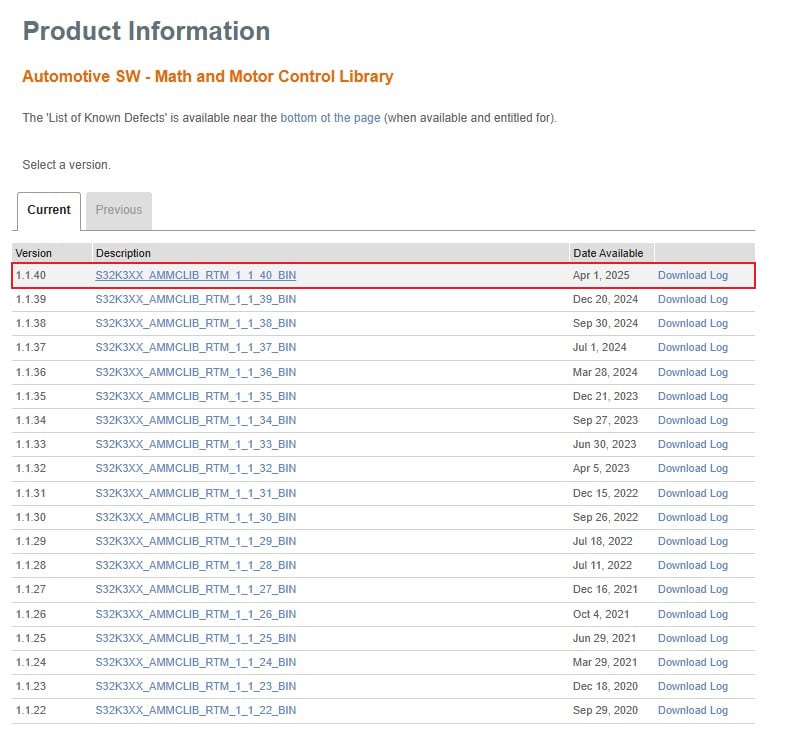
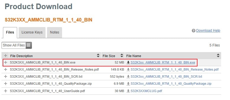
2.12 Get AMMCLib for S32K3
Download and install the latest Automotive Math and Motor Control Library set for S32K3 (version 1.1.39 or newer).
2.13 Get the Motor Control App. Software
Download and install the EV-INVERTERGEN3 motor control application software.
2.14 Get the CAN Node Driver (Optional)
Optionally, download and install drivers for your CAN interface. For example, if you use the PCAN interface,
select
your interface at the PEAK System
webpage, and then download
the Windows device driver and PCAN-View application from the download section. Install the downloaded driver and
GUI
tool.
3. Setup the Platform and Connect it to the Host PC
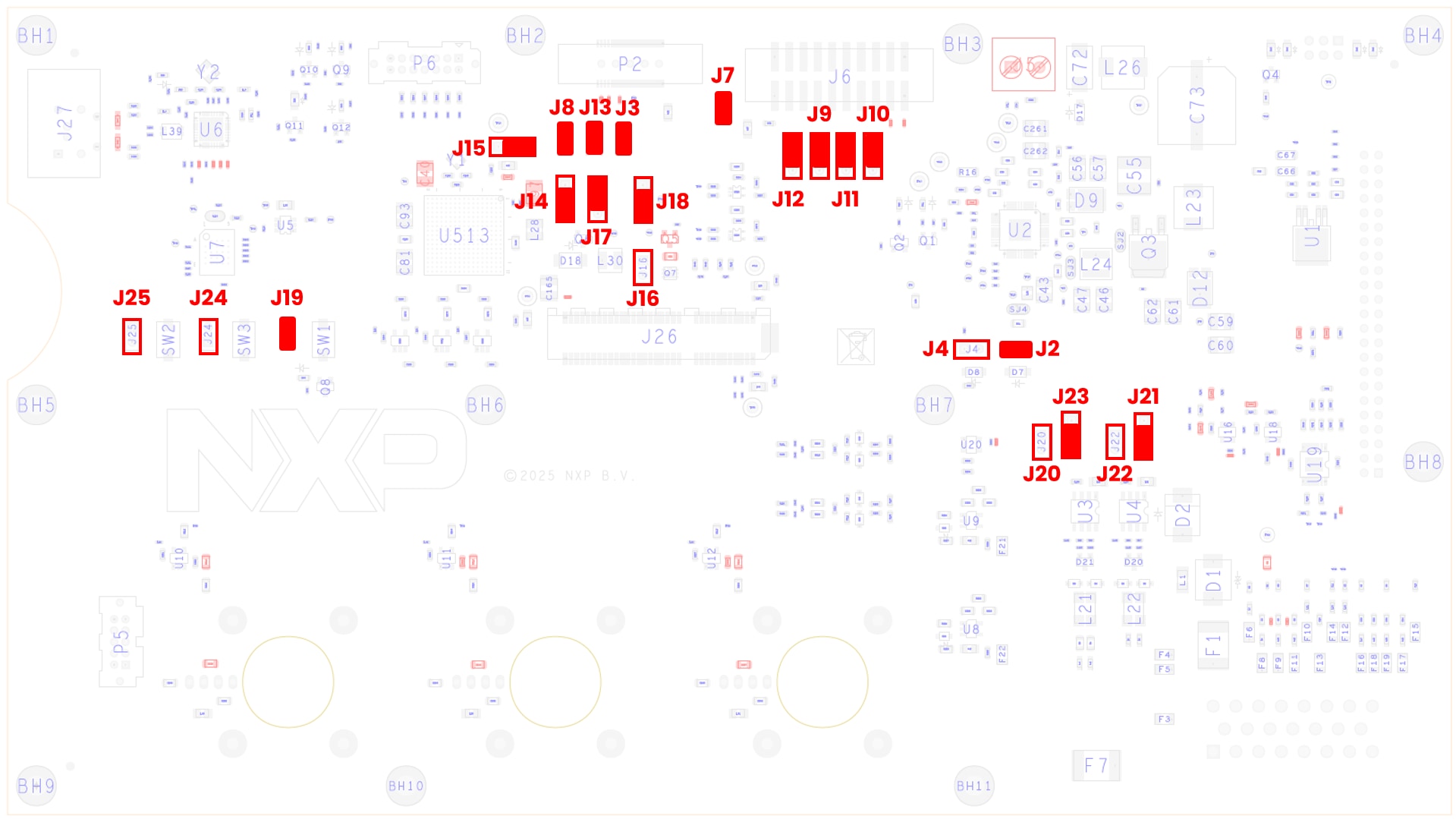
3.1 Default Jumper Positions
Check The Default Jumper Positions at the S32K396-HPWR-MC MCU Control Board.
| Jumper | State | Notes |
|---|---|---|
| J2 | CLOSED | FS26_DEBUG pin voltage connected to FS26 VBOS signal. FS26 will start in debug mode with watchdog disabled |
| J3 | CLOSED | MCU RESET_B signal connected to FS26 WAKE2 input |
| J4 | OPEN | FS26_DEBUG pin disconnected from voltage divider |
| J7 | CLOSED | VDD_HV_A connected to 20-pin Arm standard JTAG connector |
| J8 | CLOSED | MCU RESET_B signal connected to 38-pin Arm ETM Mictor connector |
| J9 | 1-2 | MCU JTAG TMS signal connected to 20-pin Arm standard JTAG connector |
| J10 | 1-2 | MCU JTAG TDO signal connected to 20-pin Arm standard JTAG connector |
| J11 | 1-2 | MCU JTAG TCK signal connected to 20-pin Arm standard JTAG connector |
| J12 | 1-2 | MCU JTAG TDI signal connected to 20-pin Arm standard JTAG connector |
| J13 | CLOSED | MCU RESET_B signal connected to 20-pin Arm standard JTAG connector |
| J14 | 2-3 | Input for 1.5 V PMOS transistor regulator connected to VDD_HV_B power domain |
| J15 | 2-3 | VREFH_R2R reference (reference voltage for all ADCs) derived from HDD_HV_A |
| J16 | OPEN | 1.5 V PMOS transistor regulator disconnected |
| J17 | 1-2 | 1.5 V PMOS transistor driven by VDD_DCDC MCU signal |
| J18 | 2-3 | 1.1 V NMOS regulator driven by NMOS_CTRL signal |
| J19 | CLOSED | SW1 RESET button connected to RESET_B signal |
| J20 | OPEN | CAN0 tranceiver Standby signal disconnected from PTE5 pin |
| J21 | 2-3 | CAN3 tranceiver Standby signal has pull-down |
| J22 | OPEN | CAN3 tranceiver Standby signal disconnected from PTF29 pin |
| J23 | 2-3 | CAN0 tranceiver Standby signal has pull-down |
| J24 | OPEN | Bypass of SW3 User Button - HDD_HV_A voltage at PTG14 pin |
| J25 | OPEN | Bypass of SW2 User Button - HDD_HV_A voltage at PTG4 pin |
3.2 Assembly the Inverter
The NXP partner Vepco may provide a hardware component setup that will help with building the inverter, or you may build your own traction inverter based on the NXP EV-INVERTERGEN3 components. The next chapter (3.3) contains the steps for building an inverter without the Vepco platform. If you use the Vepco platform, please skip chapter 3.3 and continue on chapter 3.4 from step 8.
3.3 Custom Hardware Setup
The instructions below cover electrical connectivity only. It is the customer's responsibility to assemble the physical structures (busbar, mounting hardware, and so on) required to support and connect the components in their platform.
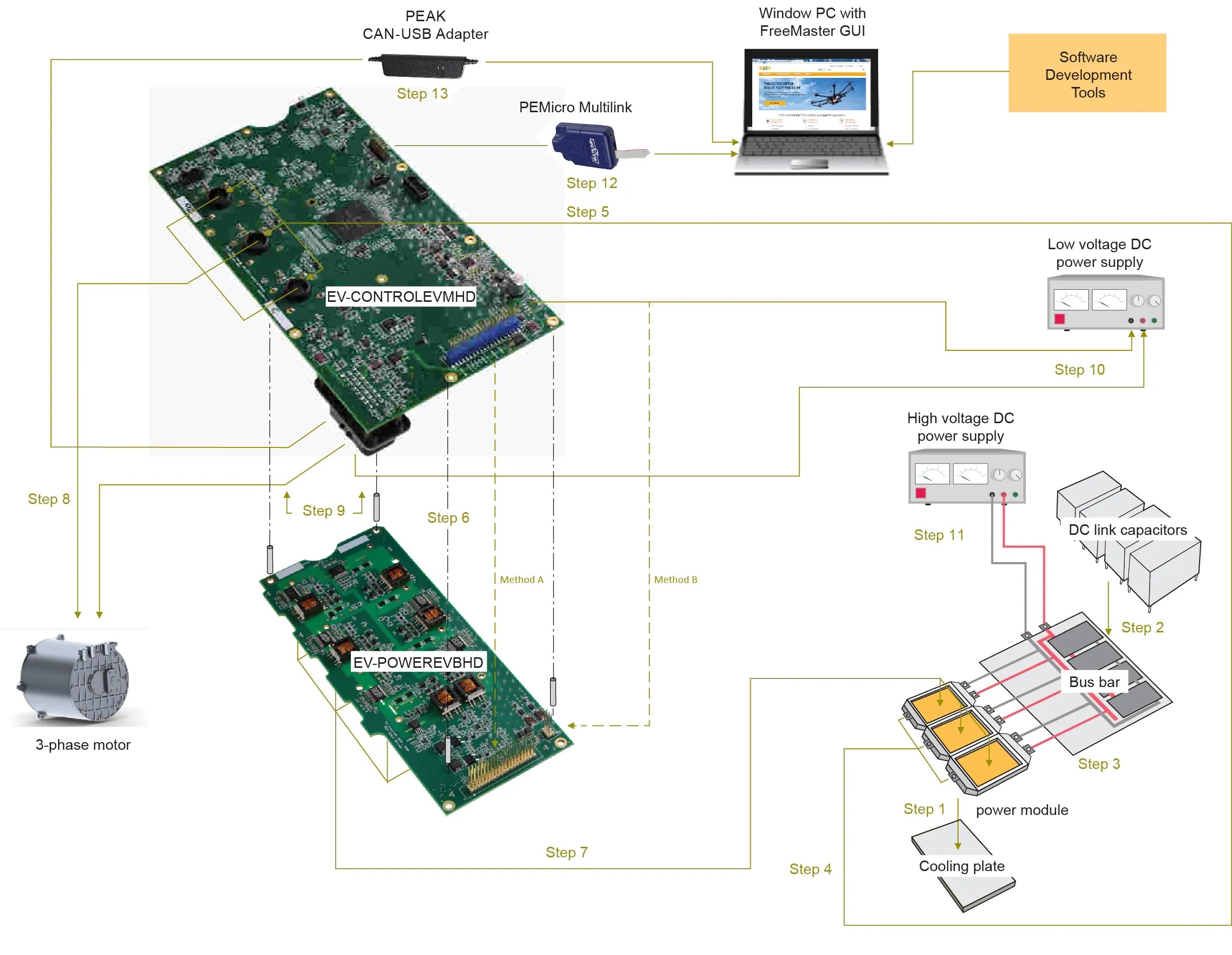
- Attach the Six-Pack (three-phase) SiC power module (Wolfspeed ECB2R1M12YM3LlSiC) to the cooling plate.
- Attach the DC link capacitors to the busbar.
- Connect the three positive DC power connectors on the power module to the corresponding connectors on the busbar. Connect the three negative DC power connectors on the power module to the corresponding connectors on the DC link busbar.
- Connect the high-voltage cables to the 3-phase output connectors on the power module. Then route each wire through the one of the three motor phase current sensors (U13, U14, U15) on the S32K396-HPWR-MC board.
- Prepare the three high-voltage cables that were routed through the current sensors in the previous step to be connected with the motor. Make sure that the A, B and C connections match.
- Connect the two enablement kit boards. The connection can be made using two different methods:
- Method A: Mount the S32K396-HPWR-MC board on top of the EV-POWEREVBHD2 board by directly connecting the 46-pin connectors (P3 and P4) and the +12 supply connectors (P4 and P2). Make sure that the pins on the lower board are completely inserted into the connectors on the upper board. Use stand-offs to provide structural support between the two boards. Notice that connecting the boards in this fashion blocks access to the test points and components on the top of the EV-POWEREVBHD2 board.
- Method B: Connect the two boards with cables. To do so, connect a 46-pin ribbon cable between the connector P3 on the S32K396-HPWR-MC board and connector P1 on the EV-POWEREVBHD2 board. In this configuration, the EV-POWEREVBHD2 board must be powered independently from the S32K396- HPWR-MC board. See step 8.
- Connect the EV-POWEREVBHD2 board to the power module. Aligning the power module is best done by aligning the pins on the surface of the power module with the power module connectors on the bottom of the EV-POWEREVBHD2 board and mounting the two units together.
3.4 Inverter Hardware Setup
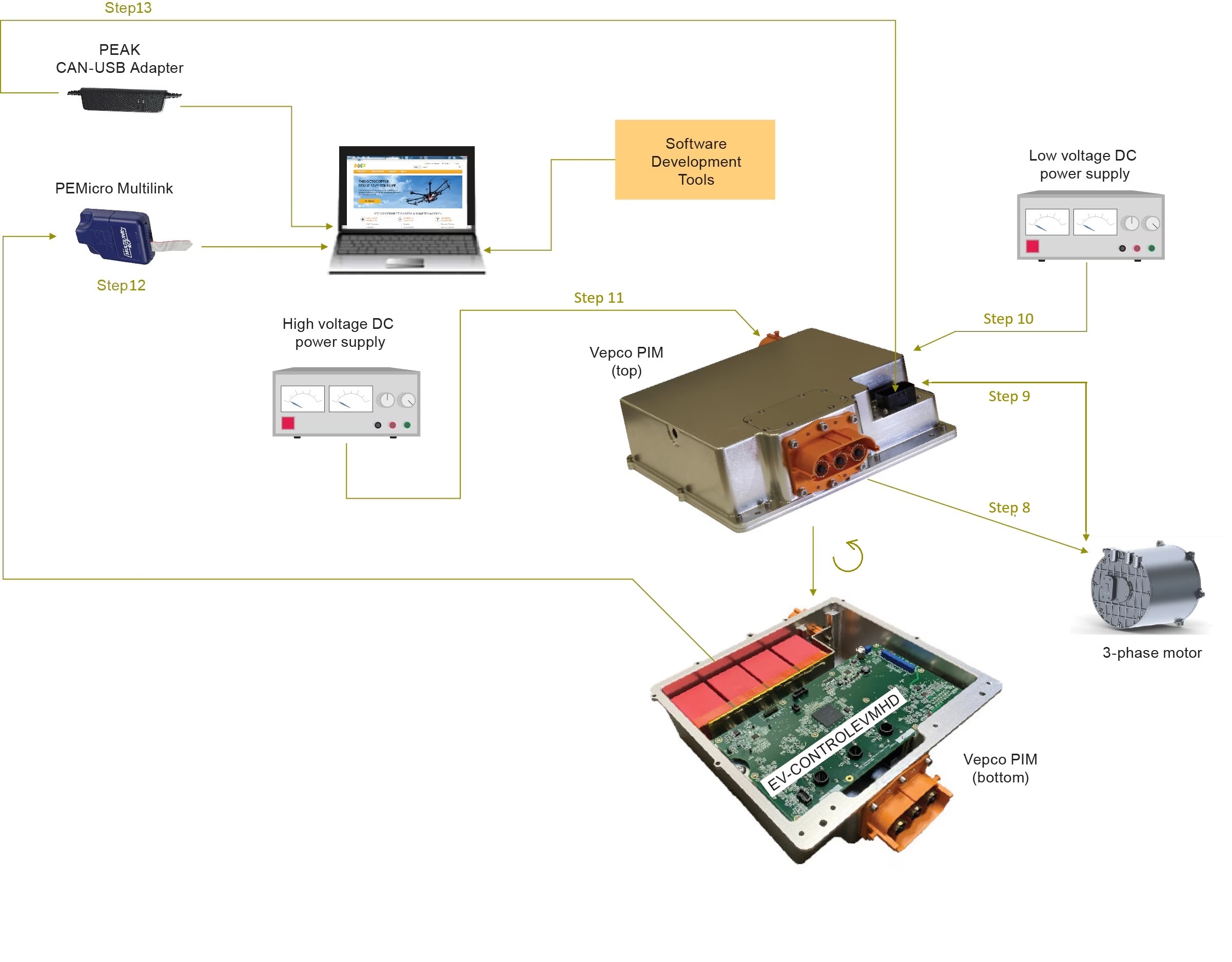
- Connect the motor to the power inverter by high-voltage cables
- Connect the motor resolver to the 23-pin P1 connector on the S32K396-HPWR-MC board. The connections are made as
follows:
- Using the two-wire high-power shielded cable, connect pin 14 and pin 21 (resolver excitation signals) on the 23-pin P1 connector to the corresponding connections on the motor. Connect the shield ground to pin 6 on the 23-pin connector
- Using the low-power cable, connect pins 8, 15, 22, and 23 (resolver sense signals) on the 23-pin connector to the corresponding connections on the motor. Connect the shield ground to pin 9 on the 23- pin connector. The signal table for the 23-pin connector is in next chapter 3.5
- Connect the low-voltage DC power supply (12 V) to the connector P4 on the S32K396-HPWR-MC board. If Method B in step 6 was used to connect the S32K396-HPWR-MC board to the EV-POWEREVBHD2 board, an additional connection must be made from the low-voltage DC power supply to the +12 supply connector (P2) on the EV-POWEREVBHD2 board. (When the two boards are mounted, as in Method A, step 6, the EV-POWEREVBHD2 draws power directly through the +12 supply connector on the S32K396-HPWR-MC board)
- Using the two-wire high-voltage cable, connect the positive connector on the high-voltage/high-current DC supply
to the positive DC link capacitor connectors on the busbar. Then connect the negative connector on the
high-voltage/high current DC supply to the negative DC link capacitor connectors on the busbar.
Warning:
HIGH DC VOLTAGES CAN BE FATAL. Use extreme caution
- Connect the 20-pin Arm JTAG debugger (for example, PEmicro Multilink) header to connector J6 on the S32K396-HPWR-MC with the pin 1 marks aligned. Connect a USB cable from the PEmicro multilink to the host PC. Both LED lights on the PEmicro multilink should be on, indicating that the JTAG bus is live and ready to communicate
- Attach the USB-CAN Interface Adapter (PEAK System) to the 23-pin connector on the bottom of the S32K396-HPWR-MC board and a USB port on the Windows PC
3.5 23-pin Connector Description

| Pin | Symbol | Description | Value |
|---|---|---|---|
| 1 | EXT_CANH_A | CANA High | transistor-transistor logic (TTL) 0 V to 5 V |
| 2 | EXT_DGND | Digital Ground | 0 V, 100 mA |
| 3 | EXT_DGND | Digital Ground | 0 V, 100 mA |
| 4 | EXT_12V_IGNIT | Ignition | 0 V to 16 V |
| 5 | EXT_MTRTD1_RTRN | Motor RTD 1 Return | Resistor - |
| 6 | EXT_RSLVR_DRIVE_SHIELD | Resolver Excitation Shield | 0 V |
| 7 | EXT_RSLVR_SENSE_SHIELD | Resolver Sense Shield | 0 V |
| 8 | EXT_RSLVR_S1 | Resolver sense S1 |
Analog 100 mA |
| 9 | EXT_CANL_A | CANA Low | TTL 0 V to 5 V |
| 10 | EXT_FAULT_OUT | Fsb1 | TTL |
| 11 | EXT_DGND | - | - |
| 12 | EXT_MTRTD1_SIG | Motor RTD 1 Signal | Resistor + |
| 13 | EXT_MTRTD2_SIG | Motor RTD 2 Signal | Resistor + |
| 14 | EXT_RSLVR_R1 | Resolver excitation R1 |
Analog 100 mA |
| 15 | EXT_RSLVR_S3 | Resolver sense S3 |
Analog 100 mA |
| 16 | EXT_CANH_B | - | - |
| 17 | EXT_CANL_B | - | - |
| 18 | EXT_12V_UNSWTCHD | Unswitched 12 V | 10 V to 16 V, 2 A |
| 19 | EXT_GND_12V_RETURN | 12 V GND | 0 V, 2 A |
| 20 | EXT_MTRTD2_RTRN | Motor RTD 2 Return | Resistor - |
| 21 | EXT_RSLVR_R2 | Resolver excitation R2 |
- |
| 22 | EXT_RSLVR_S2 | Resolver sense S2 |
- |
| 23 | EXT_RSLVR_S4 | Resolver sense S4 |
- |
4. Import, Build and Load the Motor Control Application into the MCU
Let's take your EV-INVERTERGEN3 motor control board for a test drive.
4.1 Select Application and Project Import
Select the appropriate PMSM motor control application from the installed directory.
NXP\MC_DevKits\EV-INVERTERGEN3
To import the installed application software project in the S32 Design Studio IDE for S32 Platform:
- Launch S32DS for S32 Platform
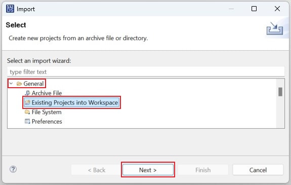
- Go to File → Import, then select General → Existing Projects into Workspace
- Navigate to the installed application directory:
NXP\MC_DevKits\EV-INVERTERGEN3, click Select Folder. Next, check the box for the option Copy projects into workspace. Then, click Finish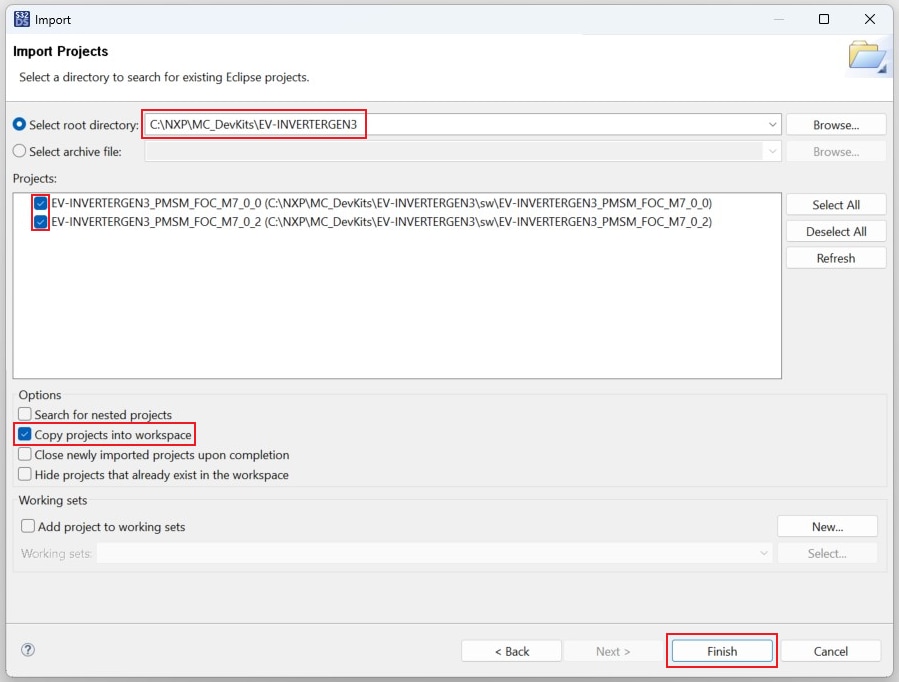
- Afterward, a new window will appear. First for the
M7_0_0project, then for theM7_0_2project. Click on Yes To All to overwrite '.settings' folder in both project directories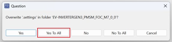
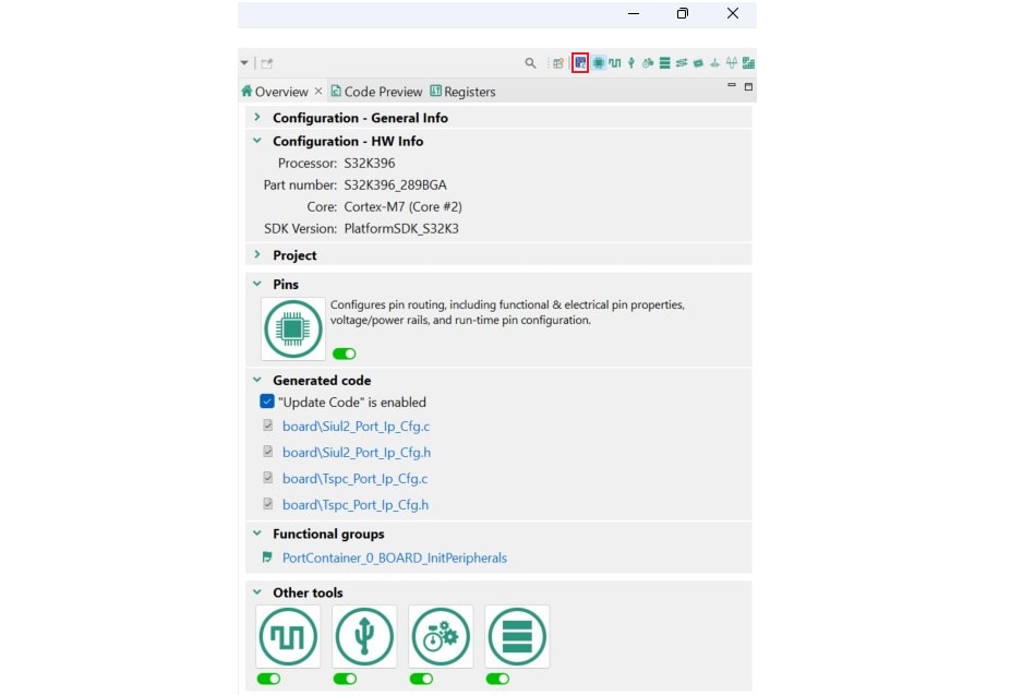
4.2 Use Configuration Tool
- Unfold the structure of the first project and double-click on
*.mexfile to open the project configuration in S32 Configuration Tool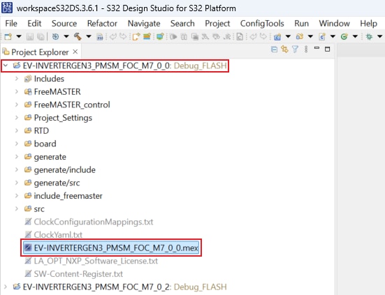
-
Ensure that you are configuring the
M7_0_0project, and click on the Update Code button for generating configuration files. Next, in the S32 Configuration Tool, click on the pop down button next to the project name and choose*.mexfile for theM7_0_2project. Click on Update Code accordingly

4.3 Upload Software and Debug
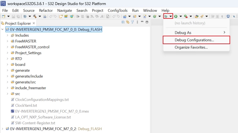
In S32DS, return back to the C/C++ perspective by clicking the button located in the upper-right corner.
Click on Debug As menu and select Debug Configurations.
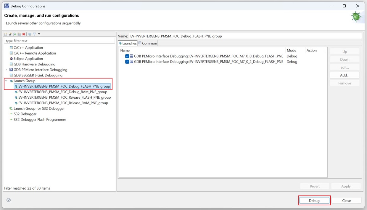
Next, expand Launch Group and click on the first launch configuration. This configuration will upload both the
M7_0_0
and M7_0_2 projects to the MCU. Click on Debug for building and uploading software into the MCU.
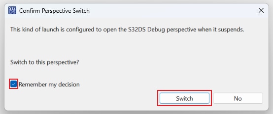
Afterward, a new window will appear. Check the box for the option Remember my decision, and click on Switch.
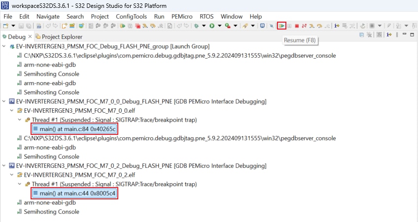
The S32DS will switch to Debug Perspective. First, press Ctrl + click on both project main() files to
highlight
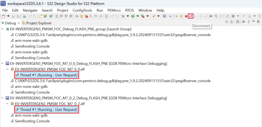
them. Next, let both projects run by clicking on Resume (or press F8).
Click on Disconnect to avoid interference between the S32DS IDE debugger and the FreeMASTER tool.
4.4 Setup the Debugging Tool
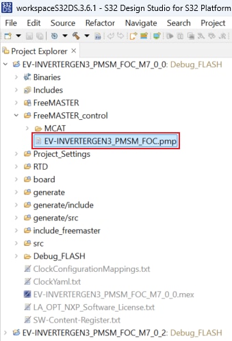
Launch the FreeMASTER application.
To open the *.pmp FreeMASTER project <selected project>\FreeMASTER_control, click File → Open Project.
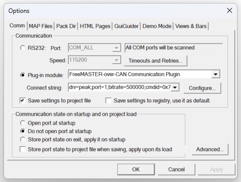
To enable communication, in the FreeMASTER toolbar, click Go (or press Ctrl + G).
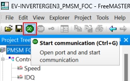
Successful communication displays in the status bar at the bottom as:
CAN;drv=peak;port=1;bitrate=500000;cmdid=0x7aa;rspid=0x7aa;tmo=1000.
5. Controlling the Application
5.1 Spin the Motor
Motor Parameters (Optional Step)
If you do not use Vepco motor, you may need to edit the motor parameters according to the used PMSM motor. In the Motor Control Application Tuning (MCAT) tool, switch to the Parameters tab and edit the values on the left side.
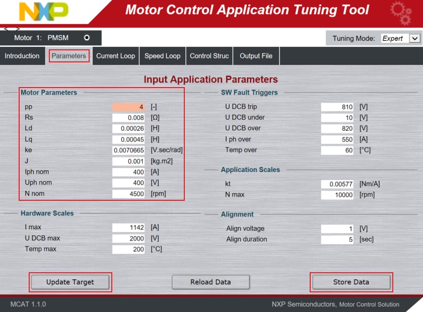
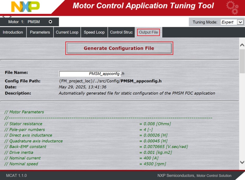
Once you finish editing the motor parameters, click on Store Data, switch to the Output File tab and click on Generate Configuration File.
The motor parameters cannot be updated at runtime, therefore, repeat step 4.3 to build the project and upload the code into MCU.
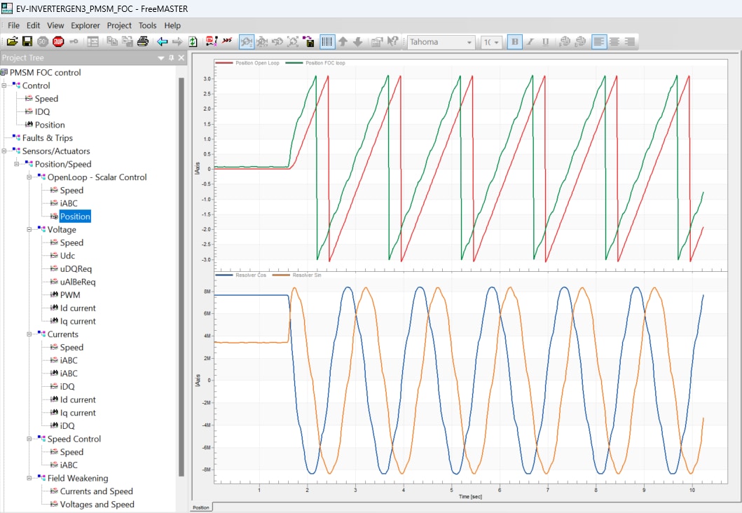
Spin the Motor in Open Loop
- In the Project Tree, select the Position view via
Sensors/Actuators→Position/Speed→OpenLoop - Scalar Control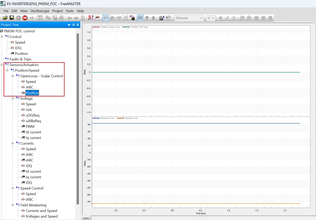
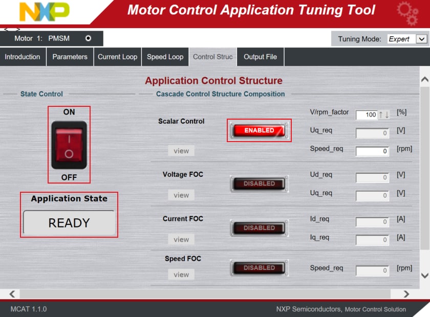
- Switch to the Control Struct tab in the MCAT tool and select the Scalar Control
- Optionally, click on the FAULT button in MCAT to clear any pending faults
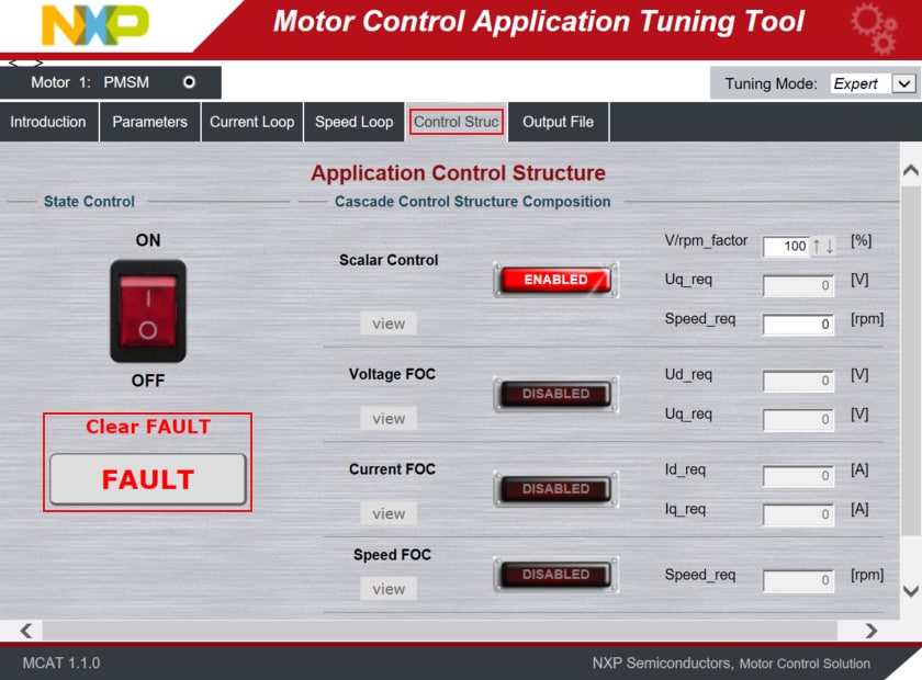
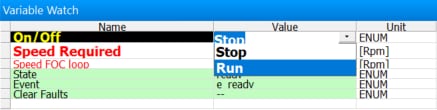
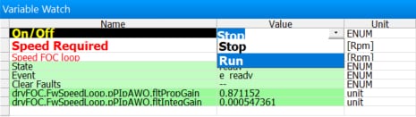
- When the state READY appears, make sure that Scalar Control is ENABLED, and switch the application to ON either
in MCAT or in the Variable Watch window by selecting the variable On/Off to Run
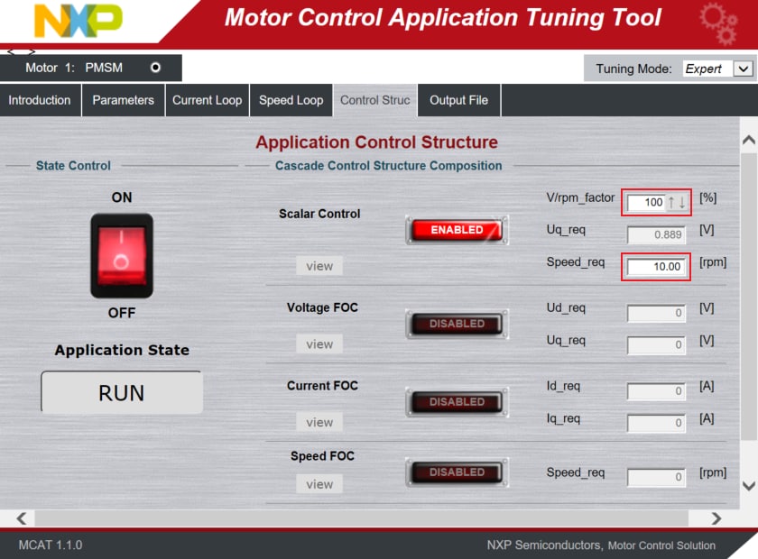
- Set the Speed_Req value in the MCAT to initiate motor rotation with a maximum up to 20 rpm, due to any missing
feedback in the
control loop. For evaluation, 10 rpm is ideal. Optionally, increase the V/rpm_factor to spin the motor
- The Scalar Control strategy (open-loop) in the EV-INVERTERGEN3 might be used to debug feedback position signals
from the resolver. Check and compare the open loop and feedback from Resolver motor positions. If the position
signals are phase-reversed, any of the two motor phase wires should be swapped to synchronize the spin rotation
of motor
and Resolver. Waveforms with synchronized spin rotation:
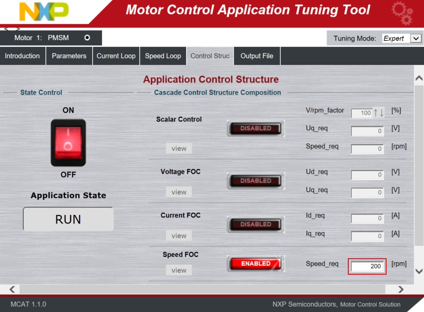
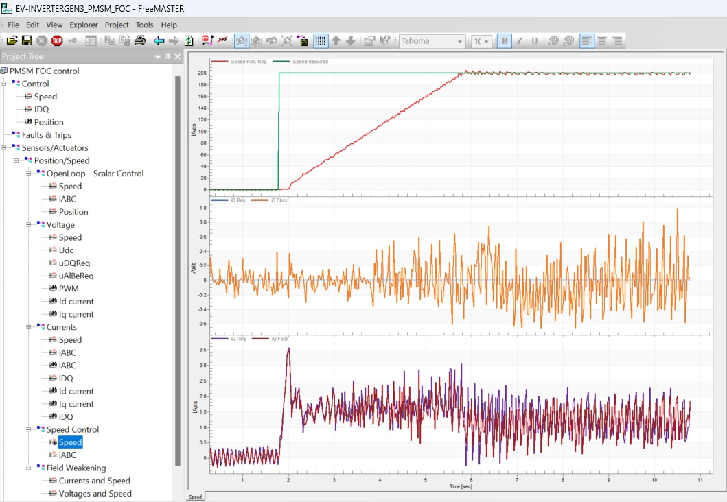
Spin the Motor in Closed Speed Loop (FOC)
- In the Project Tree, select the Speed view via
Sensors/Actuators→Position/Speed→Speed Control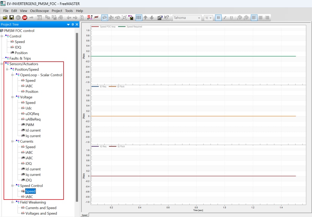
- Switch to the Control Struct tab in the Motor Control Application Tuning (MCAT) tool
- Optionally click on the FAULT button (Application State) in MCAT to clear any of pending faults
- When the state READY appears, make sure that Speed FOC is ENABLED, and switch the application to ON either in
MCAT or in the Variable Watch window by selecting the variable On/Off to Run
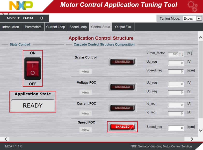
- Set the Speed_Req value in MCAT to initiate motor rotation
For an in-depth description of motor control application tuning using MCAT, see AN4642: Motor Control Application Tuning (MCAT) Tool for 3-Phase PMSM.
Design Resources
Chip Documents
Application Documents
Software
-
EV-INVERTERGEN3-SW Application
Software
-
S32K3
Standard Software Package
-
S32K3
Reference Software Package
- S32 Design Studio for S32 Platform
- Real-Time Drivers (RTD)
- Automotive Math and Motor Control Library (AMMCLib)
- FreeMASTER Run-Time Debugging Tool
- Motor Control Application Tuning (MCAT) Tool
- Model-Based Design Toolbox (MBDT)
Support
Trainings
On this page
- 2.1
Get S32 Design Studio
- 2.2
Downloading the Real-Time Drivers
- 2.3
Install the RTD Drivers
- 2.4
Download GD3162 Driver
- 2.5
Install GD3162 Driver
- 2.6
Download FS26 Driver
- 2.7
Install FS26 Driver
- 2.8
Download eTPU SW
- 2.9
Install eTPU SW
- 2.10
Get FreeMASTER Comm. Driver
- 2.11
Get FreeMASTER Application Tool
- 2.12
Get AMMCLib for S32K3
- 2.13
Get the Motor Control App. Software
- 2.14
Get the CAN Node Driver (Optional)
- 3.1
Default Jumper Positions
- 3.2
Assembly the Inverter
- 3.3
Custom Hardware Setup
- 3.4
Inverter Hardware Setup
- 3.5
23-pin Connector Description