Getting Started with the FRDM33772BTPLEVB
Contents of this document
-
Get Started
-
Get to Know the Hardware
-
Configure Hardware
Sign in to save your progress. Don't have an account? Create one.
Purchase your Evaluation Board for MC33772 with Isolated Daisy Chain Communication
1. Get Started
The NXP analog product development boards provide an easy-to-use platform for evaluating NXP products. The boards support a range of analog, mixed-signal and power solutions. They incorporate monolithic integrated circuits and system-in-package devices that use proven high-volume technology. NXP products offer longer battery life, a smaller form factor, reduced component counts, lower cost and improved performance in powering state-of-the-art systems.
This page will guide you through the process of setting up and using the FRDM33772BTPLEVB evaluation board.
1.1 Kit Contents/Packing List
The FRDM33772BTPLEVBcontents include:
- Assembled and tested FRDM33772BTPLEVB in an antistatic bag
- Quick start guide
1.2 Additional Hardware
In addition to the kit contents, the following hardware is necessary or beneficial when working with this kit.
- A 3- to 6-cell battery pack, such as BATT-14AAAPACK, or a battery pack emulator, such as BATT-6EMULATOR
2. Get to Know the Hardware
2.1 Board Description
The FRDM33772BTPLEVB serves as a hardware evaluation tool in support of NXP's MC33772B device. The FRDM33772BTPLEVB is an ideal platform for rapid prototyping of MC33772B-based applications that involve current, voltage and temperature sensing.
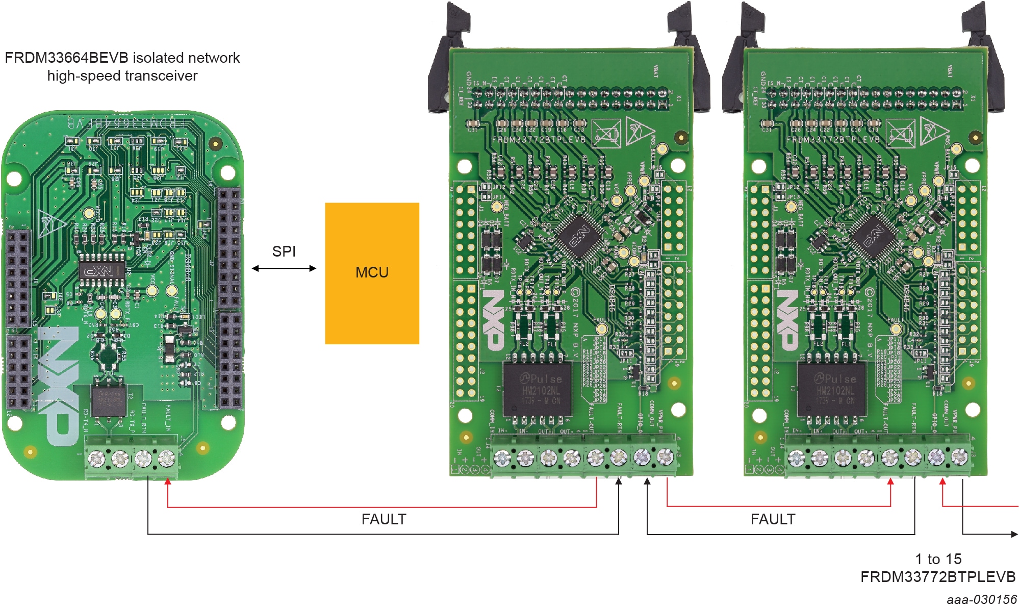
The FRDM33772BTPLEVB includes a transformer enabling communication in a high- speed isolated communication network. The information is digitally transmitted to a microcontroller for processing.
2.2 Board Features
- Daisy chain device connection
- LED indicator for operation mode
- Cell-balancing resistors
- Cell sense input with RC filter
- GPIO: digital I/O, wake-up inputs, convert trigger inputs, ratiometric analog inputs, analog inputs with absolute measurements
- EEPROM (connected to the IC with I²C interface) to store user-defined calibration parameters
- Fault detection pin report
- Current measurement input via external shunt
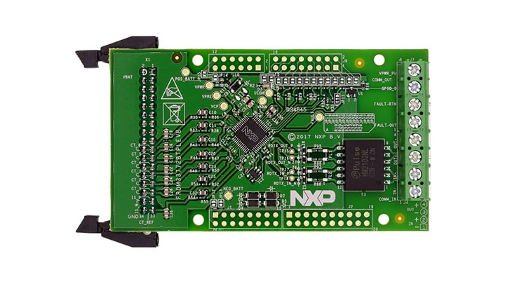
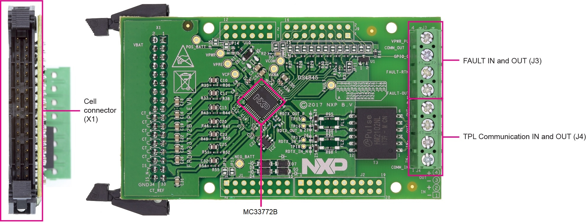
2.3 Board Components
Overview of the FRDM33772BTPLEVB evaluation board.
3. Configure Hardware
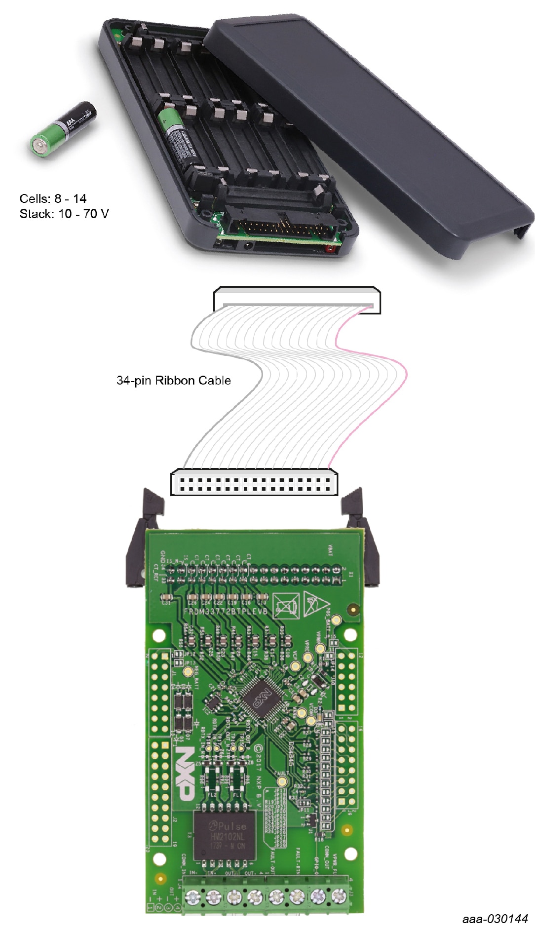
3.1 Battery Stack Connection
A minimum of 3 cells and a maximum of 6 cells can be monitored. NXP provides a 6- cell battery emulator board, BATT-6EMULATOR. This board provides an intuitive way to change the voltage across any of the 6 cells of an emulated battery pack as well as the voltage across an emulated current sense shunt resistor. In addition, a battery pack (BATT-14AAAPACK) using AAA batteries is available to support FRDM33772BTPLEVB.
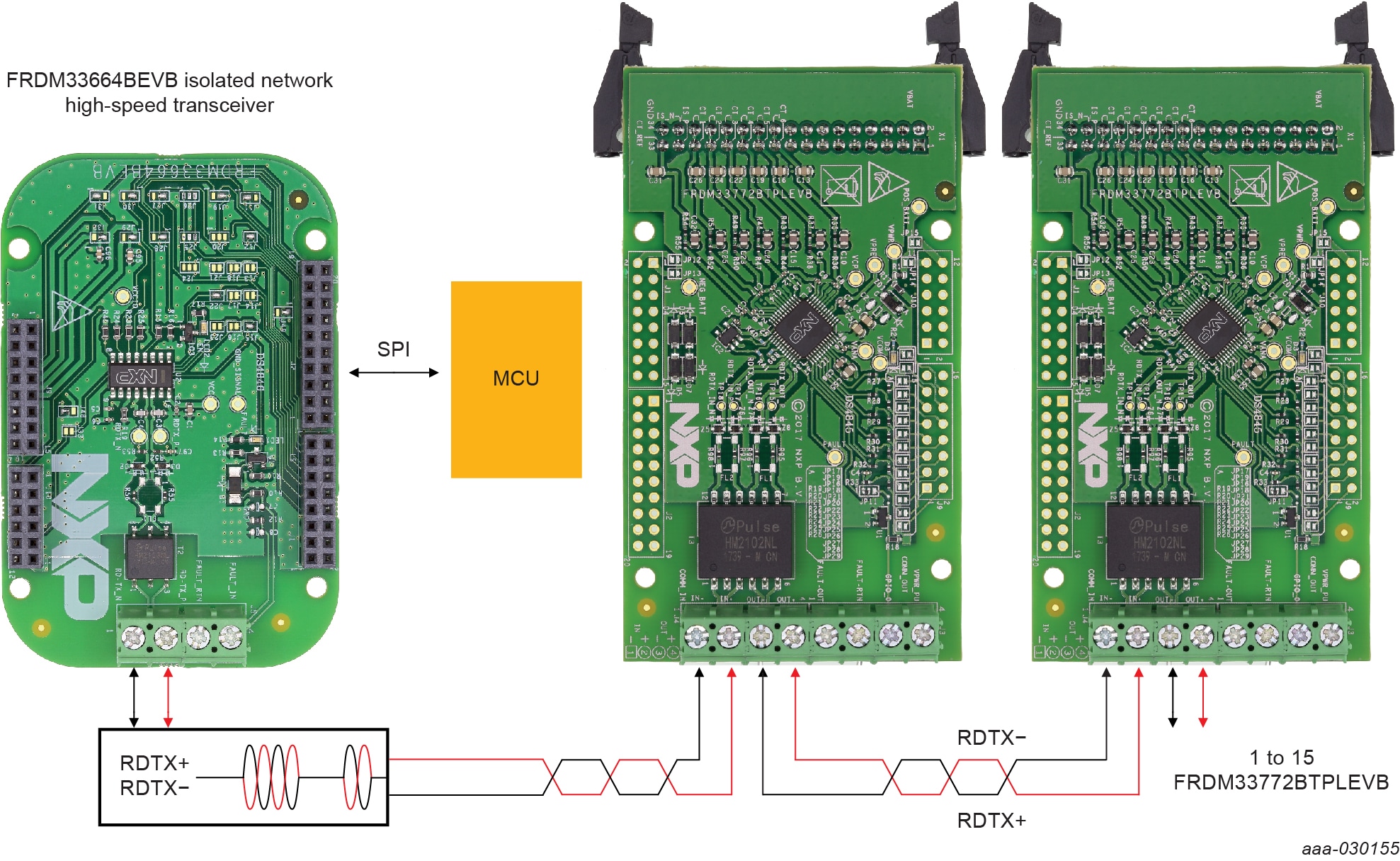
3.2 TPL Communication Connection
3.3 Fault Chain Connection
The FAULT chain connection is optional. When used, it connects through the FAULT (J3) connector.
Design Resources
Additional Documents
Product Summary Page
- The product summary page for MC33772B is at: MC33772B.
References
In addition to our MC33772B: 6-Channel Li-ion Battery Cell Controller IC page, you may also want to visit:
Tool pages:
- FRDM33664BEVB: Evaluation Board for MC33664ATL Isolated Network High-Speed Transceiver
- BATT-14AAAPACK: Configurable Battery Pack to supply the MC33771/MC33772 EVB's
- BATT-6EMULATOR: 6-cell Battery Pack to supply MC33772 EVB's
- FRDM33772BTPLEVB: Evaluation Board for MC33772 with Isolated Daisy Chain Communication