Getting Started with the FRDM33772CSPEVB Evaluation Board
Contents of this document
-
Get Started
-
Get Hardware
-
Configure Hardware
Sign in to save your progress. Don't have an account? Create one.
Purchase your FRDM33772CSPEVB
1. Get Started
The NXP analog product development boards provide an easy-to-use platform for evaluating NXP products. The boards support a range of analog, mixed-signal and power solutions. They incorporate monolithic integrated circuits and system-in-package devices that use proven high-volume technology. NXP products offer longer battery life, a smaller form factor, reduced component counts, lower cost, and improved performance in powering state-of-the-art systems.
This page will guide you through the process of setting up and using the FRDM33772CSPEVB evaluation board.
1.1 Kit Contents and Packing List
The FRDM33772CSPEVB contents include:
- Assembled and tested FRDM33772CSPEVB in an antistatic bag
- Quick Start Guide
1.2 Additional Hardware
In addition to the kit contents, the following hardware is necessary or beneficial when working with this kit.
- A 3-cell to 6-cell battery pack, such as BATT-14AAAPACK, or a battery pack emulator, such as BATT-6EMULATOR
2. Get Hardware
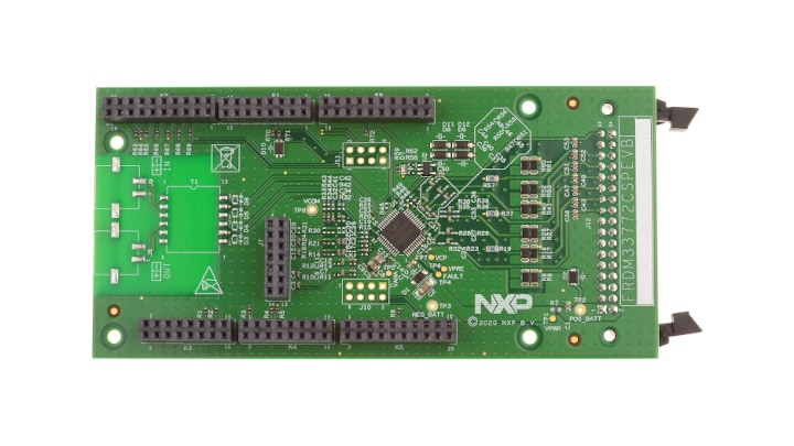
2.1 Board Description
The FRDM33772CSPEVB allows the user to exercise all the functions of the MC33772C battery controller cell.
It is stacked onto an S32K144EVB. SPI communication is done through connector K1 to K6. The
FRDM33772CSPEVB is supplied when connected to a battery cell stack through connector J12. The
S32K144EVB is supplied through its USB connection when connected to a PC.
2.2 Board Features
- Standard SPI communication
- LED indicator for operation mode
- Cell-balancing resistors
- Cell sense input with RC filter
- General-purpose input/output (GPIO): digital I/O, wake-up inputs, convert trigger inputs, ratiometric analog inputs, analog inputs with absolute measurements
- EEPROM (connected to the IC with I²C-bus interface) to store user-defined calibration parameters
- Fault detection pin report
- Current measurement input via external shunt
2.3 Board Components
Overview of the FRDM33772CSPEVB evaluation board.
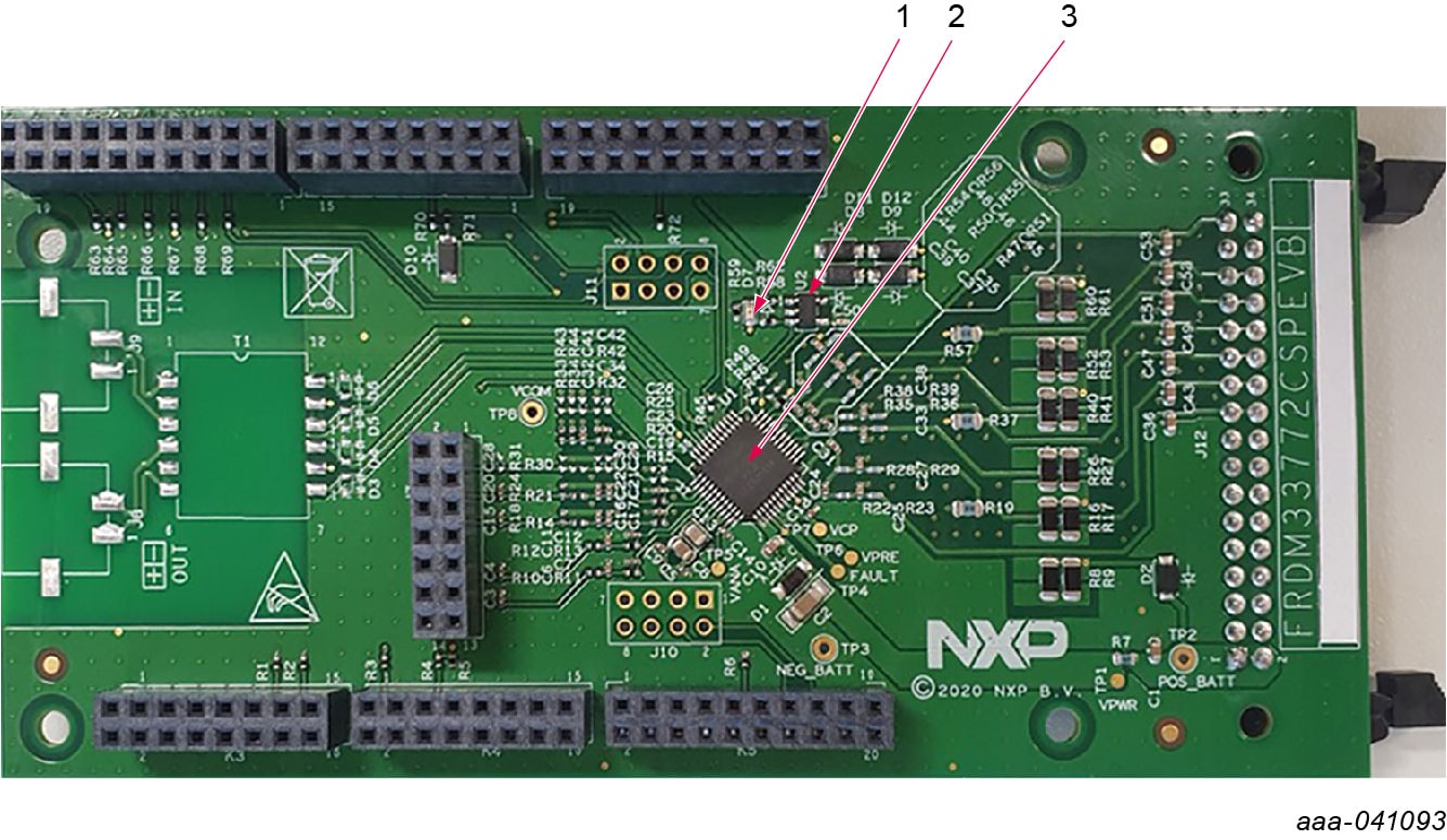
| Number | Label | Name | Description |
|---|---|---|---|
| 1 | D7 |
VCOM LED | Indicates whether the device is in normal mode or in low-power mode. |
| 2 | U2 |
24LC01BT-I/OT | IC memory EEPROM. |
| 3 | U1 |
MC33772C | Battery cell controller IC. |
3. Configure Hardware
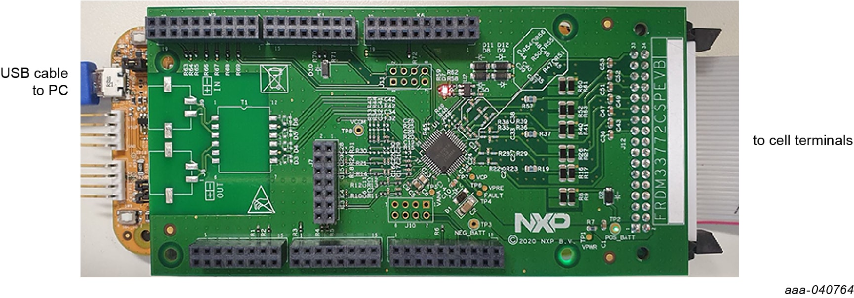
3.1 Configure Hardware
The FRDM33772CSPEVB can be configured as a shield board connected to an S32K144EVB board.
When both boards are connected together (see Figure 1), the SPI connector is directly connected with the MCU SPI pins. In this configuration, power is supplied to the S32K144EVB through a USB cable connected between the S32K144EVB board and a PC. No external power supply is required.
3.2 Battery Emulator Connection
The FRDM33772CSPEVB supports the use of a battery cell emulator such as NXP's BATT-6EMULATOR board and BATT-14AAAPACK.
The BATT-6EMULATOR is a 6-cell battery emulator board that provides an intuitive way to change the voltage across any of the 6 cells and four voltage outputs in order to emulate four external NTC.
The emulator board can be connected to the FRDM33772CSPEVB connector J12 using the provided
supply cable.
To exercise the FRDM33772CSPEVB in combination with the BATT-6EMULATOR, a graphical user interface is available at MC33771C/MC33772C (Battery Cell Controller) Evaluation GUI.
Design Resources
Board Documents
Additional Resources
In addition to our MC33772C: 6-Channel Li-ion Battery Cell Controller IC page, you may also want to visit:
Tool Pages:
- S32K144EVB: S32K144 Evaluation Board
- BATT-14AAAPACK: Configurable Battery Pack to supply the MC33771/MC33772 EVB’s
- BATT-6EMULATOR: 6-cell Battery Pack to supply MC33772 EVB’s
Application Pages:
Hardware pages:
Software pages:
Support
Forums
Connect with other engineers and get expert advice on designing with the FRDM33772CSPEVB on one of our community sites.