Getting Started with the FRDM665SPIEVB Evaluation Board
Contents of this document
-
Out of the Box
-
Get Hardware
-
Configure Hardware
Sign in to save your progress. Don't have an account? Create one.
Purchase your FRDM665SPIEVB
1. Out of the Box
The NXP analog product development boards provide an easy-to-use platform for evaluating NXP products. The boards support a range of analog, mixed-signal and power solutions. They incorporate monolithic integrated circuits and system-in-package devices that use proven high-volume technology. NXP products offer longer battery life, a smaller form factor, reduced component counts, lower cost and improved performance in powering state-of-the-art systems.
This page will guide you through the process of setting up and using the FRDM665SPIEVB board.
1.1 Kit Content and Packing List
The FRDM665SPIEVB contents include:
- MC33665A SPI EVB, SPI to four transformer physical layer (TPL) interface EVB
- One TPL daisy chain cable; two-wire twisted pair daisy chain interface cable
- Power cable
- Quick Start Guide
1.2 Additional Hardware
In addition to the kit contents, the following hardware is necessary or beneficial when working with this board.
- External dual power supply 10 V to 18 V/2 A (optional)
- EVBs of battery cell controller (BCC) devices from NXP
- S32K344EVB-Q172 evaluation and development board for S32K344 from NXP
- 14 cell battery pack or a battery emulator, such as BATT-14CEMULATOR
2. Get Hardware
2.1 Board Features
- Request SPI
- Response SPI
- Onboard analog termination for daisy chain communication to BCC devices
- Configurable VIO voltage
- Configurable VDD5V from internal and external supply
- DIP switch for configuring the SPI of MC33665A to operate with or without crystals
- Reset switch for the device and board
- LED display for the status of power
- Connectors to interface directly with S32K344EVB launchpad
- Connectors for external interface to general-purpose input/output (GPIO) and I²C-bus
2.2 Board Description
The FRDM665SPIEVB serves as a hardware evaluation tool in support of the MC33665A device of NXP. The MC33665A is a gateway router that can route TPL messages from the MCU to four different TPL ports. It is designed for use in both automotive and industrial applications. The device can route both TPL2 and TPL3 messages. The FRDM665SPIEVB is an ideal board for rapid prototyping of the MC33665A for SPI interface to the MCU.
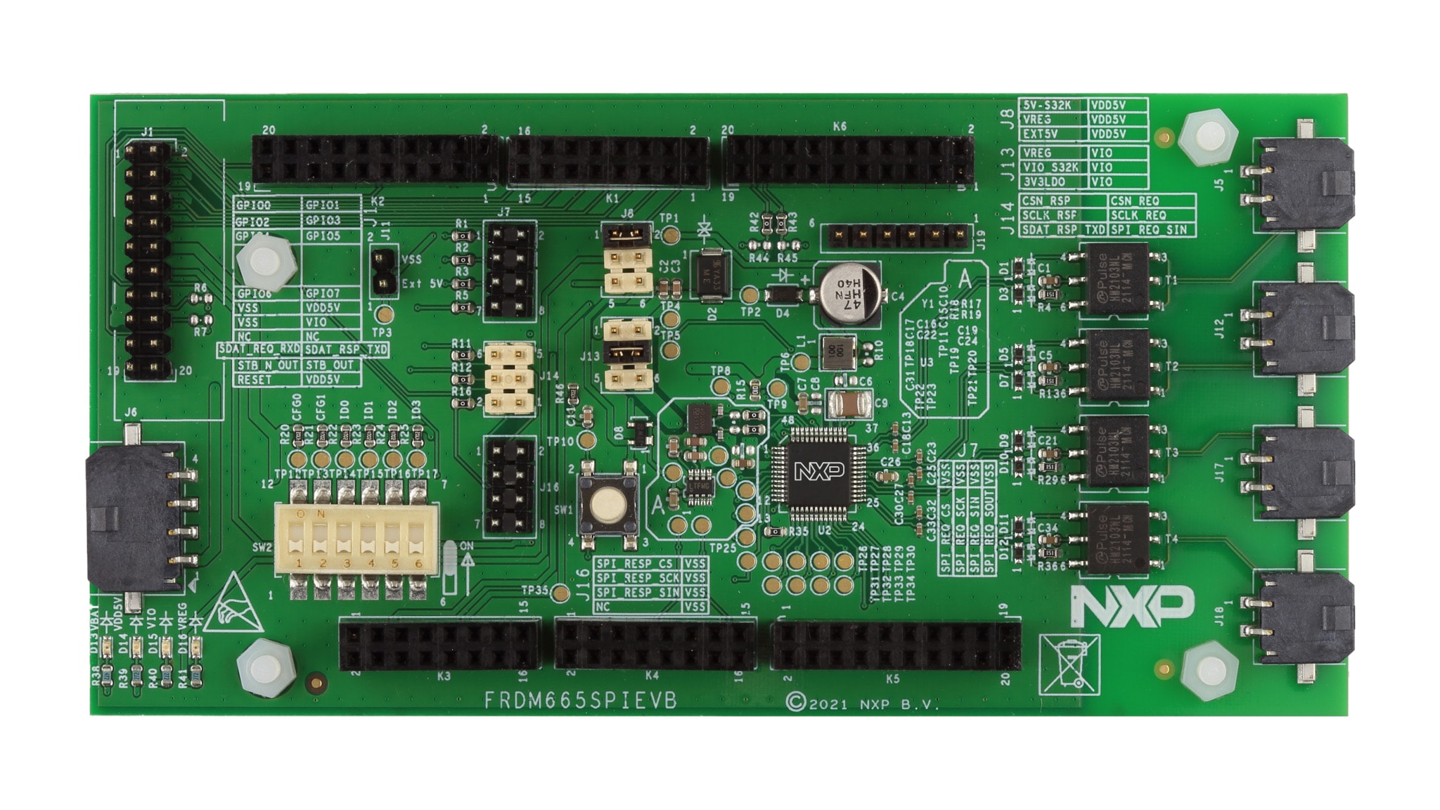
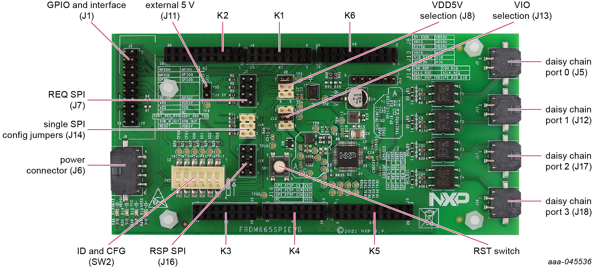
2.3 Board Components
Overview of the FRDM665SPIEVB board.
3. Configure Hardware
FRDM665SPIEVB can be configured as a stacked board to S32K344EVB.
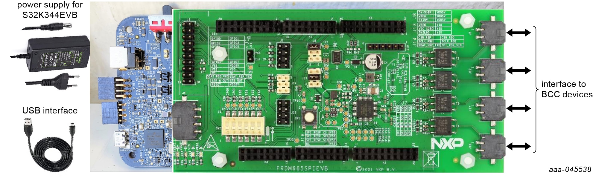
3.1 Stacked Board Configuration
As shown in Figure 1, the FRDM665SPIEVB and the S32K344EVB can be connected and stacked for communication (dual SPI) and power interface. Power can be supplied to the FRDM665SPIEVB with K3 connector from the S32K344EVB. External power supply to FRDM665SPIEVB with J6 connector is optional. Check the power LEDs D15 and D14 during this setup or configuration. In case it is not glowing, check the jumper settings at J8 and J13. Jumpers J8 and J13 must be connected appropriately to have VDD5V and VIO to MC33665A from S32K344EVB.
For stacked board configuration, you must remove the four plastic holders placed on four corners of the FRDM665SPIEVB.
3.2 External Board Configuration
FRDM665SPIEVB can be interfaced with external microcontroller boards for SPI and GPIO interface of the MC33665A. Connect 12 V at J6 or external 5 V to J11 interface. Select the 5 V to MC33665A with jumper J8. Care should be taken in selecting the right VIO for both external microcontroller board and FRDM665SPIEVB. Jumper J13 can be used to select the right VIO for the MC33665A. Before powering up the boards, crosscheck the VIO selection for the microcontroller board and FRDM665SPIEVB. Care must be taken for the interconnection wires of request SPI and response SPI from the external MCU to the board to FRDM665SPIEVB. It must be twisted pair with short GND wires interconnecting the boards (FRDM665SPIEVB and MCU).
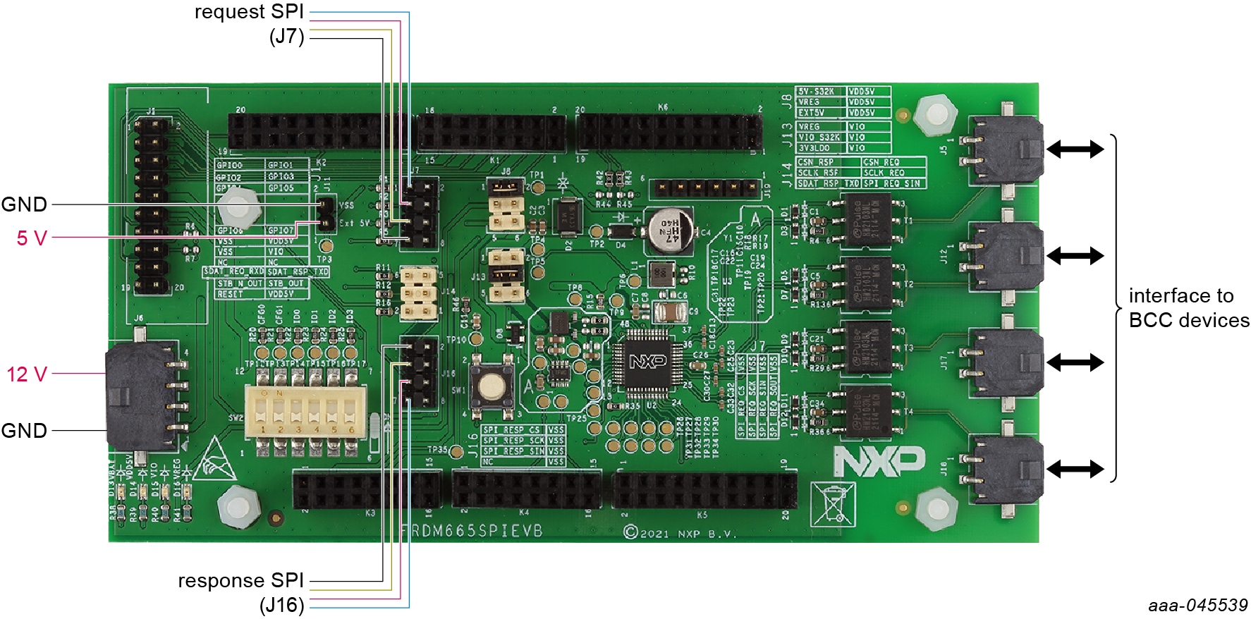
Communication can be established by the MCU to BCC devices connected on different daisy chain ports with SPI interface on MC33665A.
Design Resources
Board Information
Additional Resources
In addition to our MC33665A: General Purpose BMS Communication TPL Transceiver and CAN Gateway page, you may also want to visit:
Application Pages:
Support
Forums
Connect with other engineers and get expert advice on designing with the FRDM665SPIEVB on our community site.