Getting started with the KIT6X02AF2T1 Evaluation Board
Contents of this document
-
Out of the Box
-
Get to Know the Hardware
-
Configure Hardware
Sign in to save your progress. Don't have an account? Create one.
Purchase your Evaluation Board for BMA6X02 with CAN FD
1. Out of the Box
The NXP analog product development boards provide an easy-to-use platform for evaluating NXP products. The boards support a range of analog, mixed-signal and power solutions. They incorporate monolithic integrated circuits and system-in-package devices that use proven high-volume technology. NXP products offer longer battery life, a smaller form factor, reduced component counts, lower cost and improved performance in powering state-of-the-art systems.
This page will guide you through the process of setting up and using the KIT6X02AF2T1 board.
1.1 Kit Contents and Packing List
The kit contents include:
- Assembled and tested the evaluation board in an antistatic bag
- Quick start guide
- KIT6402AF2T1 - CAN to electrical transport protocol link (ETPL) gateway board
- Cable for supply and CAN interface
- ETPL cable - two-wire twisted pair TPL cable (50 cm)
1.2 Additional Hardware
The purpose of the KIT6402AF2T1 is to build and interface from CAN to transport protocol link (TPL). The KIT6402AF2T1 can be used in any regular CAN environment. It can also be used with NXP PC software (that is, scripting GUI) to communicate via TPL to attached NXP devices (that is, BMA7118, BMA7418, BMA8420 or similar). To use the KIT with the NXP PC software, extra hardware is required.
1.3 Software
Installing software is necessary to work with this evaluation board. All listed software is available on the evaluation board's information page at KIT6x02AF2T1 or from the provided link.
- GUI
- Flexera
2. Get to Know the Hardware
The main features of the KIT6X02AF2T1 are:
- Communication link from CAN to TPL and back
- Flexera
- CAN communication speeds up to 1 MHz for regular CAN, and for CAN-FD, up to 5 MHz
- Supply and mode control of the CAN physical layer interface via the integrated voltage regulator of the BMA6X02C
- Two galvanically isolated ETPL ports
- Supports the TPL3 protocol version
- Two status LEDs
2.1 Board Features
The main features of the KIT6X02AF2T1 are:
- Communication link from CAN to TPL and back
- CAN communication speeds up to 1 MHz for regular CAN, and for CAN-FD, up to 5 MHz
- Supply and mode control of the CAN physical layer interface via the integrated voltage regulator of the BMA6X02C
- Two galvanically isolated ETPL ports
- Supports the TPL3 protocol version
- Two status LEDs
The KIT6X02AF2T1 serves as a hardware tool-supporting evaluation of ETPL devices via a CAN interface. Control of the CAN bus can be done with any CAN environment. If no specific environment is available, there is also a software solution from NXP available that allows the evaluation of a BMS system.
2.2 Board Description
The KIT6X02AF2T1 serves as a hardware tool-supporting evaluation of ETPL devices via a CAN interface. Control of the CAN bus can be done with any CAN environment. If no specific environment is available, there is also a software solution from NXP available that allows the evaluation of a BMS system.
2.3 Board Components
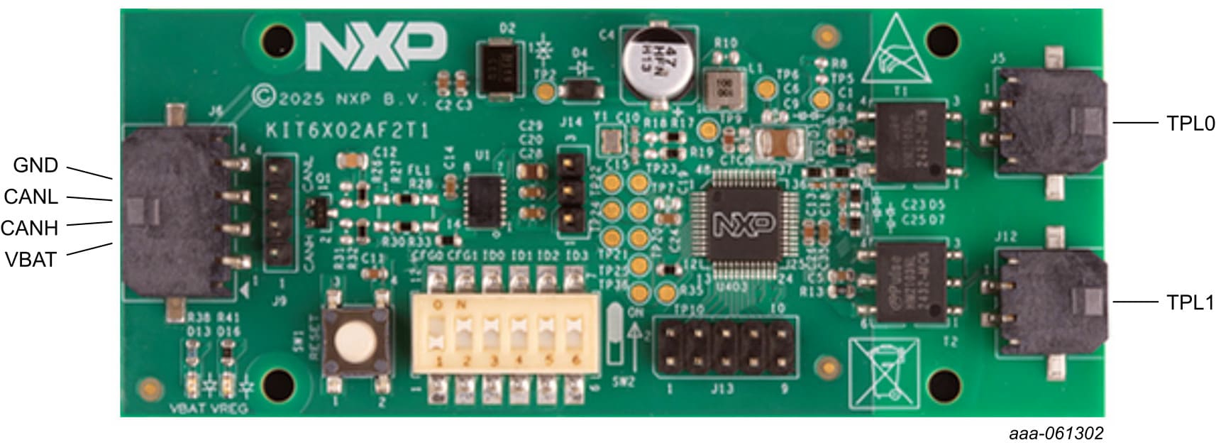
Connector J6 connects the KIT6402AF2T1 to the supply and CAN cable.
| Pin number | Connection | Description |
|---|---|---|
| 1 | VBAT | Battery supply Apply a voltage from 6 V to 18 V for normal operation of the board. |
| 2 | CANH | CAN high-line |
| 3 | CANL | CAN low-line |
| 4 | GND | Supply ground |
Connectors J1 and J2 connects to the KIT6402AF2T1 TPL ports 0 and 1.
| Pin Number | Connection | Description |
|---|---|---|
| 1 | TPL0_P | TPL port 0 (positive) |
| 2 | TPL0_N | TPL port 0 (negative) |
| Pin Number | Connection | Description |
|---|---|---|
| 1 | TPL1_P | TPL port 1 (positive) |
| 2 | TPL1_N | TPL port 1 (negative) |
The KIT6X02AF2T1 offers access to various debugging points to allow a fast evaluation of the product. The debugging points are shown in Figure 2.
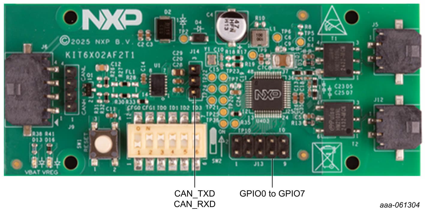
The CAN traffic can be monitored either on the CAN physical layer (J9), or on the digital pins (J14). See Table 4
for details of the settings.
| Header number | Function | Description |
|---|---|---|
| 1 | GND | Ground as reference |
| 2 | CAN_TXD | CAN transmitt |
| 3 | CAN_RXD | CAN receive |
The BMA6X02C can route various status and sideband signals to the GPIO pins. These status signals can be useful for traffic monitoring and debugging. See the data sheet of the BMA6X02C for further details.
3. Configure Hardware
3.1 Configure Hardware
The KIT6X02AF2T1 has several configuration options. The most important ones are the CAN speed and CAN ID configuration of the BMA6X02C. This configuration can be changed with the switches on the board (See Figure 3).
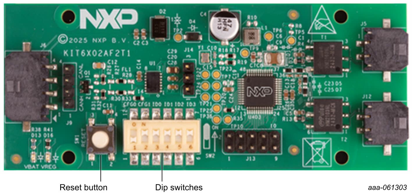
The reset button initiates a reset of the BMA6X02C on the board. The DIP switches (SW2) configure the CAN
communication speed and the CAN-ID used for communication. See for details of the settings in Table 6.
Design Resources
Board Documents
In addition to our KIT6X02AF2T1: Product description page, you may also want to visit: Product pages: S32K358BMU, S32K344BMU.