- Analog Toolbox
- Getting Started with the KIT6X02AP2T1
Getting Started with the KIT6X02AP2T1
Contents of this document
-
Out of the Box
-
Get to Know the Hardware
-
Configure Hardware
Sign in to save your progress. Don't have an account? Create one.
Purchase your Computer to (ETPL) Dongle
1. Out of the Box
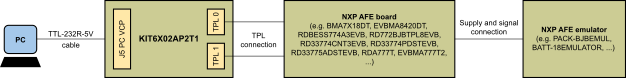
The purpose of the KIT6X02AP2T1 is to interface NXP PC software (that is, Device Evaluation GUI) to TPL attached NXP devices (that is, BMA7118, BMA7418, BMA8420 or similar). See the software section of the board.
This document guides the user through the process of using the KIT6X02AP2T1.
1.1 Kit Contents/Packing List
The KIT6X02AP2T1 kit includes:
- KIT6X02AP2T1 - personal computer (PC) to electrical transport protocol link (ETPL) gateway board
- TTL-232R-5V - USB to RS232 cable (1.8 m)
- ETPL cable - two-wire twisted pair TPL cable (50 cm)
2. Get to Know the Hardware
2.1 Board Overview
The NXP analog product development boards provide an easy-to-use platform for evaluating NXP products. The boards support a range of analog, mixed-signal and power solutions. They incorporate monolithic integrated circuits and system-in-package devices that use proven high-volume technology.
The KIT6X02AP2T1 serves as a hardware tool supporting evaluation of ETPL devices with software running on a PC. This board can be directly connected to a USB port of a PC and interfaced via a virtual COM port (VCP).
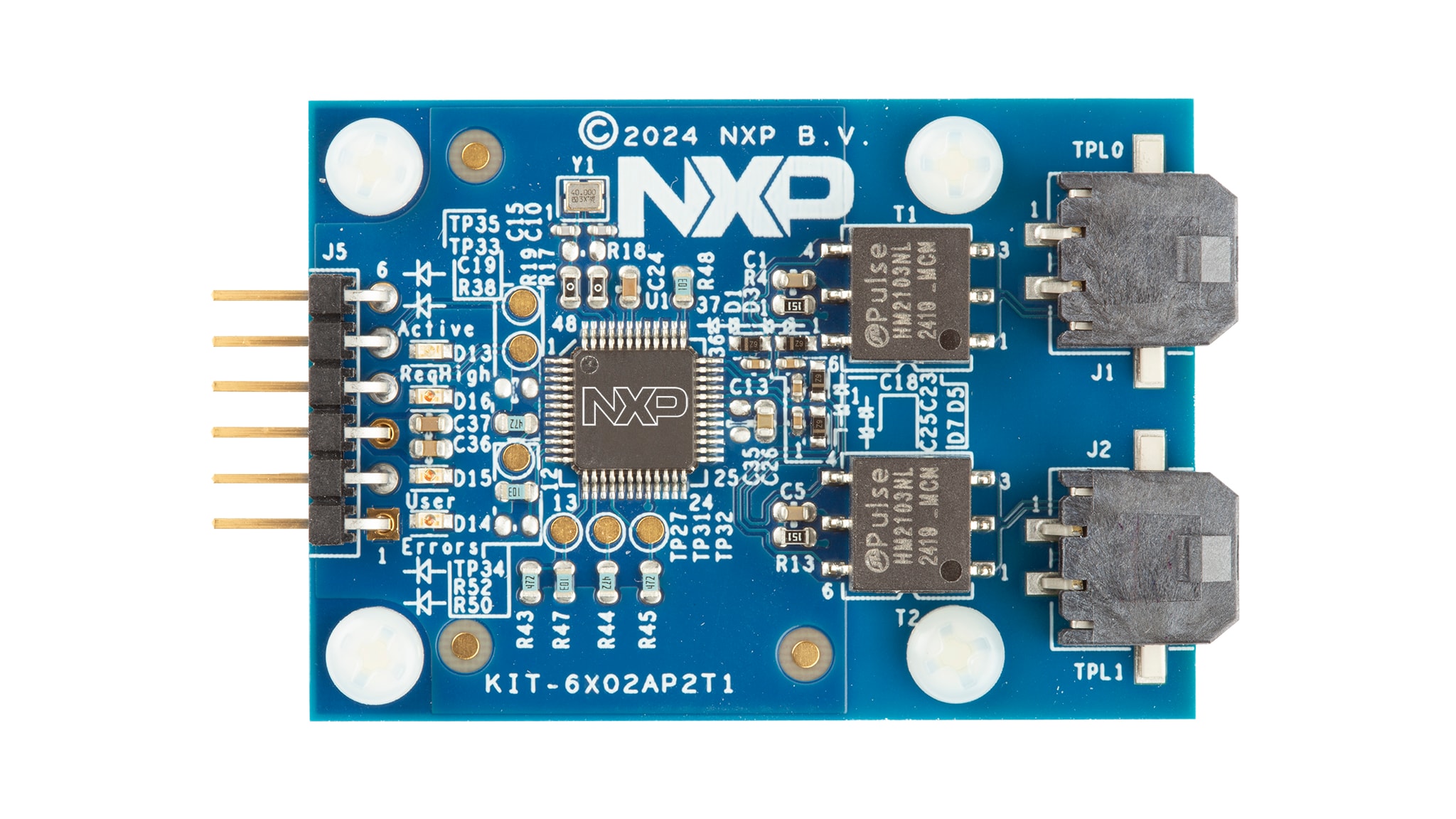
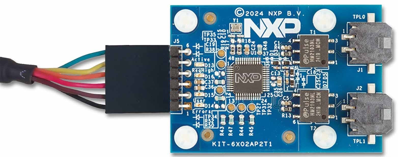
Figure 1 is an overview of the KIT6X02AP2T1.
2.2 Board Features
The main features of the KIT6X02AP2T1 are:
- Direct control from a PC via USB connection (VCP)
- VCP communication speed 2 MBd
- Supply of the KIT6X02AP2T1 from USB
- Two galvanically isolated ETPL ports
- Supports the TPL3 protocol version
- Four status LEDs
2.3 Board Components
The KIT6X02AP2T1 allows the user to interface ETPL chains/devices with software running on a PC.
The kit includes a UART-to-USB translator cable (TTL-232R-5V) and an ETPL cable. The UART-to-USB translator cable interfaces with the UART-based BMA6402 gateway and provides the 5 V supply. The two ETPL ports allow connection to NXP evaluation boards or customer boards having the NXP ETPL interface.
The KIT6X02AP2T1 has the following LEDs to indicate information to the user. The D13 indicates the operating mode (active) of the BMA6402. The D14, D15 and D16 LEDs are connected to GPIOs of the BMA6402 and depend on the configuration of the BMA6402 device. The default use is listed in Table 1.
| LED | Description | BMA6402 SIGNAL |
|---|---|---|
D13 - green |
Active: indicates the BMA6402 operating state | STB_OUT_N |
D16 - orange |
ReqHigh (default use): indicates Request Queue High status | GPIO0 |
D15 - orange |
User (default use): optional for User purpose | GPIO1 |
D14 - red |
Error (default use): optional indicating error status | GPIO3 |
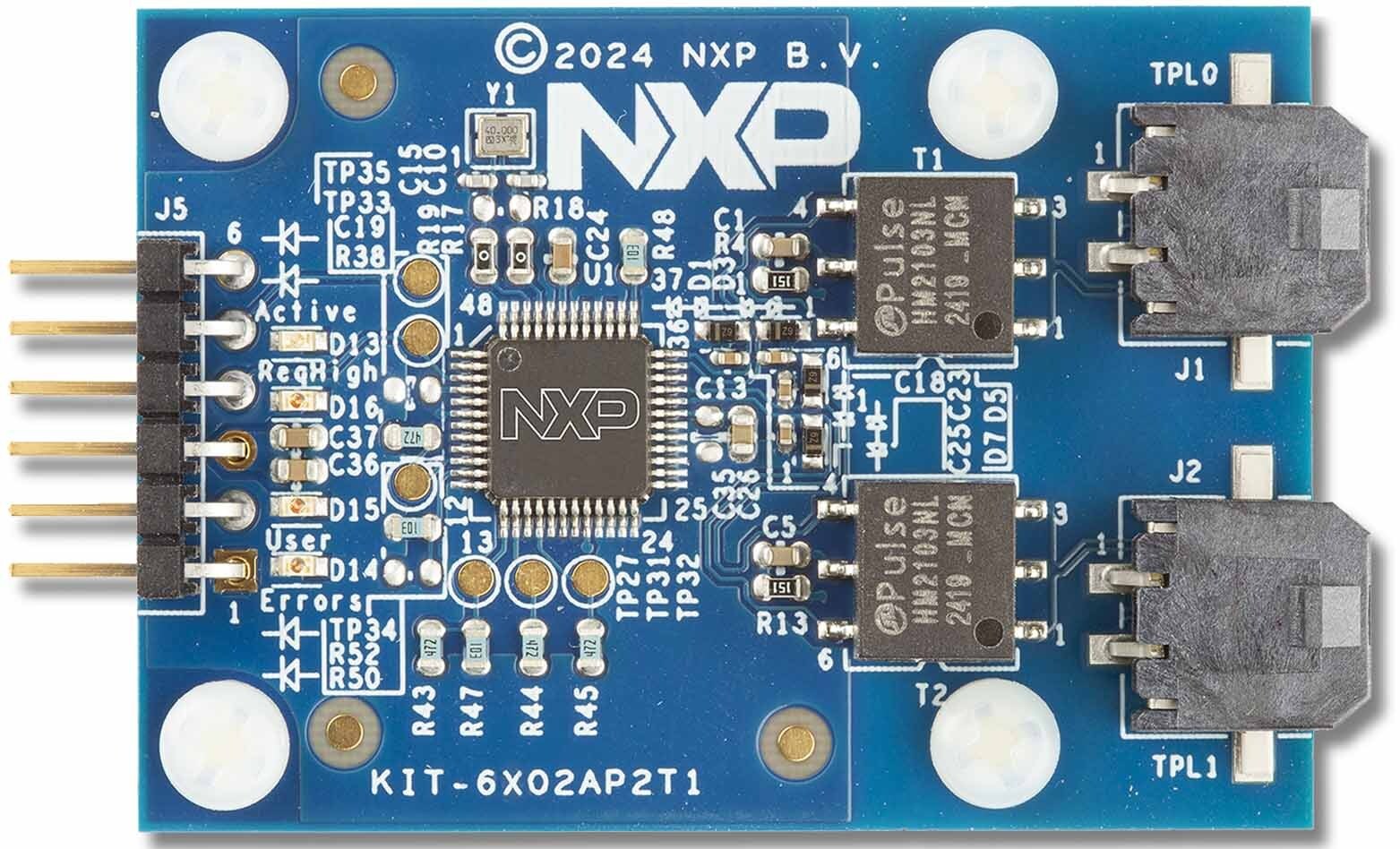
2.4 Connectors
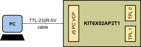
The KIT6X02AP2T1 has one connector to interface to a PC and two TPL ports.
Connector J5 connects the KIT6X02AP2T1 to the UART-to-USB translator cable. Pin 1 of the TTL-232R-5V (black wire) must be connected to the J5 Pin 1 as shown in Figure 3.
| Pin number | Connection | Description |
|---|---|---|
1 |
GND | Ground |
2 |
ReqHigh | Request Queue High output (connect to PC UART CTS input) |
3 |
VDD5V | 5 V supply input |
4 |
ReqData | Request Data input (connect to PC UART TXD output) |
5 |
RspData | Response Data output (connect to PC UART RXD input) |
6 |
Hold | Hold input (optional connect to PC UART RTS output) |
Connectors J1 and J2 connects to the KIT6X02AP2T1 TPL ports 0 and 1.
| Pin number | Connection | Description |
|---|---|---|
1 |
TPL1_P |
TPL port 1 (positive) |
2 |
TPL1_N |
TPL port 1 (negative) |
| Pin number | Connection | Description |
|---|---|---|
1 |
TPL0_P |
TPL port 0 (positive) |
2 |
TPL0_N |
TPL port 0 (negative) |