Getting Started with the OMPCA9959LEDEV
Contents of this document
-
Get Started
-
Get to Know the Hardware
-
Configure Hardware
Sign in to save your progress. Don't have an account? Create one.
Purchase your OMPCA9959LEDEV | PCA9959 Development Tool
1. Get Started
The NXP analog product development boards provide an easy-to-use platform for evaluating NXP products. The boards support a range of analog, mixed-signal and power solutions. They incorporate monolithic integrated circuits and system-in-package devices that use proven high-volume technology. NXP products offer longer battery life, a smaller form factor, reduced component counts, lower cost and improved performance in powering state-of-the-art systems.
This page will guide you through the process of setting up and using the OMPCA9959LEDEV evaluation board.
1.1 Kit Contents/Packing List
The OMPCA9959LEDEV contents include:
- Assembled and tested OMPCA9959LEDEV (24-channel SPI serial bus 63 mA/5.5 V constant current LED driver) board in an antistatic bag
- One USB A to micro B cable
- Quick Start guide
1.2 Additional Hardware
In addition to the kit contents, the following hardware is necessary or beneficial when working with this kit.
- Microcontroller board for SPI communication
- Fluke 88-5 Multimeter
- TEK MSO4054 500 MHz 2.5 GS/s 4-channel oscilloscope
1.3 Windows PC Workstation
This evaluation board requires a Windows PC workstation. Meeting these minimum specifications should produce great results when working with this kit.
- USB-enabled computer with Windows 7 or Windows 10
2. Get to Know the Hardware
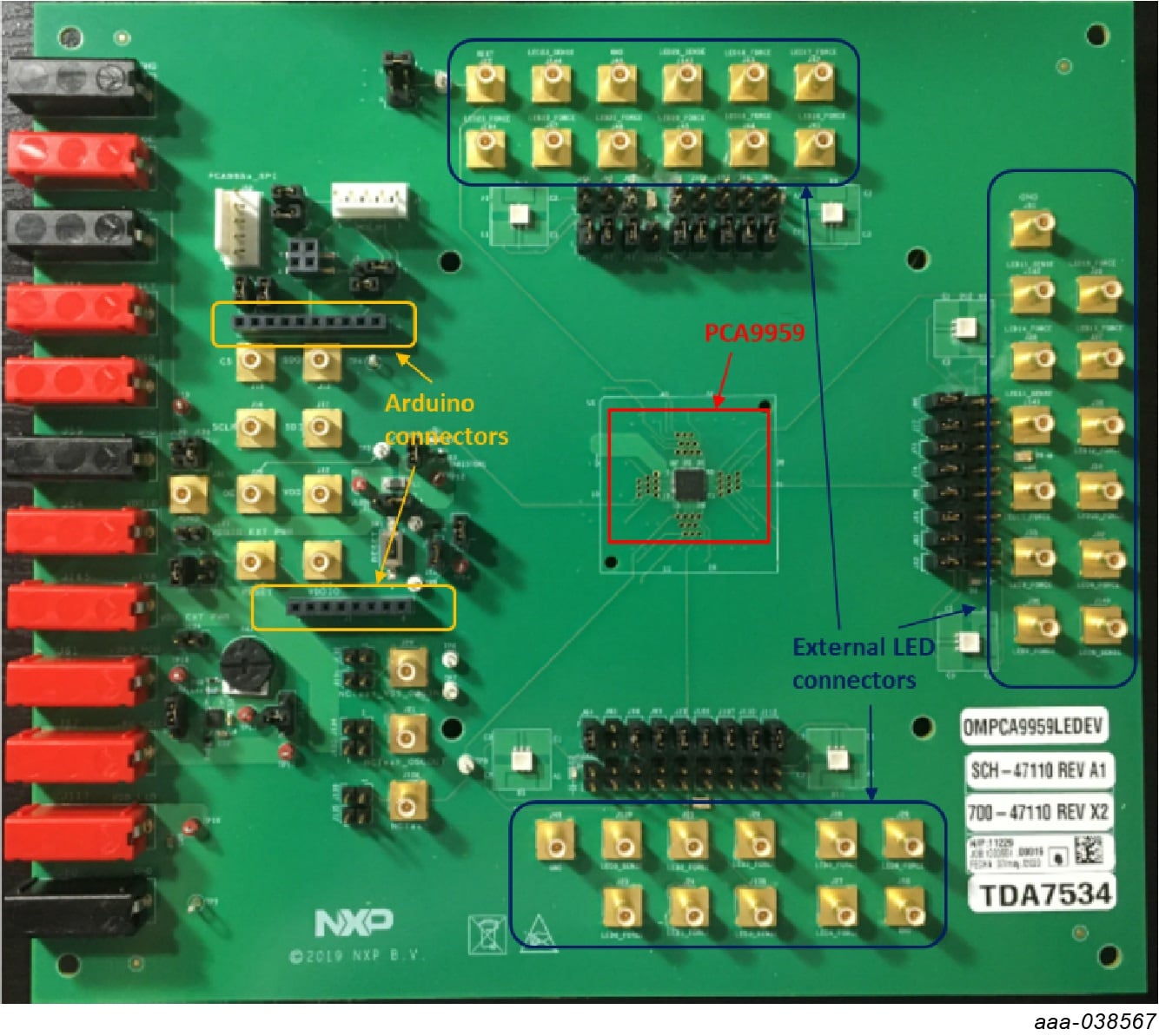
2.1 Board Features
- A complete evaluation platform for the PCA9959 24-channel SPI-bus 63 mA/5.5 V constant current LED driver
- Easy-to-use GUI-based software demonstrates the capabilities of the PCA9959
- Onboard infrared, blue and RGB LEDs for variable experiments
- Convenient test points for easy scope measurements and signal access
- USB interface to the host PC
- Power supply from USB port
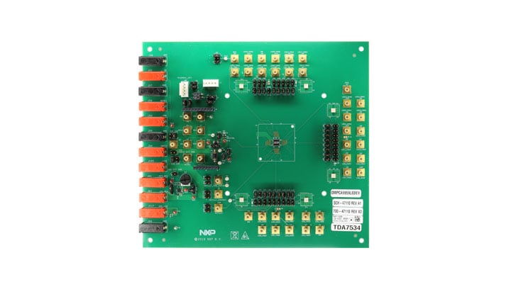
2.2 Board Description
The OMPCA9959LEDEV evaluation board features LEDs for color mixing, blinking and dimming demonstrations. A graphical interface allows the user to easily explore the different functions of the driver. The board can be connected in series with other SPI-bus demo boards.
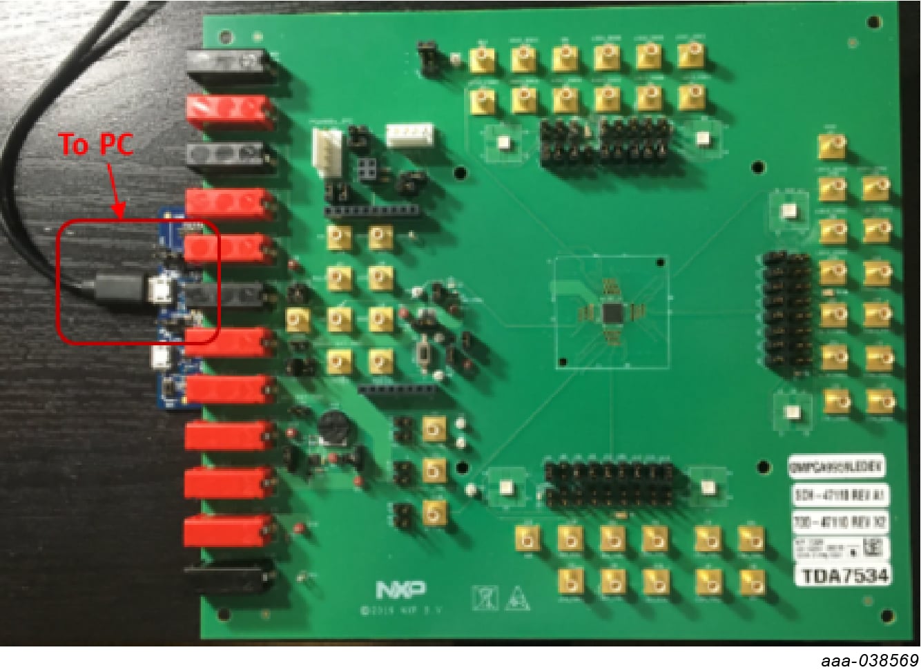
3. Configure Hardware
To configure the hardware, complete the following procedure:
- The OMPCA9959LEDEV evaluation board is connected to the OM13089 MCU board using two connectors (
J1andJ2on the OMPCA9959LEDEV board andJ1andJ8on the OM13089 board) - The OM13089 MCU board communicates with the PCA9959 demo GUI through PC USB port and uses SPI bus to communicate to PCA9959
Design Resources
Board Documents
Additional Resources
Product Summary Page
Tool Summary Page
- OMPCA9959LEDEV | PCA9959 Development Tool: This page provides overview information, technical and functional specifications, ordering information, documentation and software. The "Getting Started" guide provides quick-reference information applicable to using the OMPCA9959LEDEV board, including the downloadable assets
References
In addition to our PCA9959: 24-channel SPI serial bus 63 mA/5.5 V constant current LED driver page, you may also want to visit:
Product Pages:
Tool Pages:
Hardware Pages:
Software Pages: