Getting Started with the PACK-BJBEMUL Evaluation Board
Contents of this document
-
Out of the Box
-
Get Hardware
-
Configure Hardware
Sign in to save your progress. Don't have an account? Create one.
Purchase your PACK-BJBEMUL
1. Out of the Box
The NXP analog product development boards provide an easy-to-use platform for evaluating NXP products. The boards support a range of analog, mixed-signal and power solutions. They incorporate monolithic integrated circuits and system-in-package devices that use proven high-volume technology. NXP products offer longer battery life, a smaller form factor, reduced component counts, lower cost and improved performance in powering state-of-the-art systems.
This page guides you through the process of setting up and using the PACK-BJBEMUL board.
1.1 Kit Contents and Packing List
| Description Quantity | Quantity |
|---|---|
| High-voltage measurement cable (orange) | 10 |
| Chassis connection cable (black) | 1 |
| Two points general-purpose cable (pyrotechnic switch connection, crash signal connection) | 4 |
| Current measurement and temperature measurement cable | 2 |
1.2 Extra Hardware
The PACK-BJBEMUL requires an external +12 V power supply.
2. Get Hardware
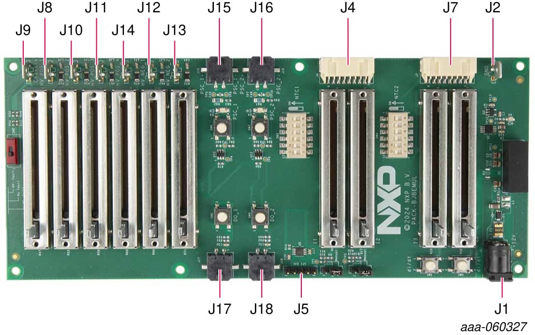
2.1 Kit Overview
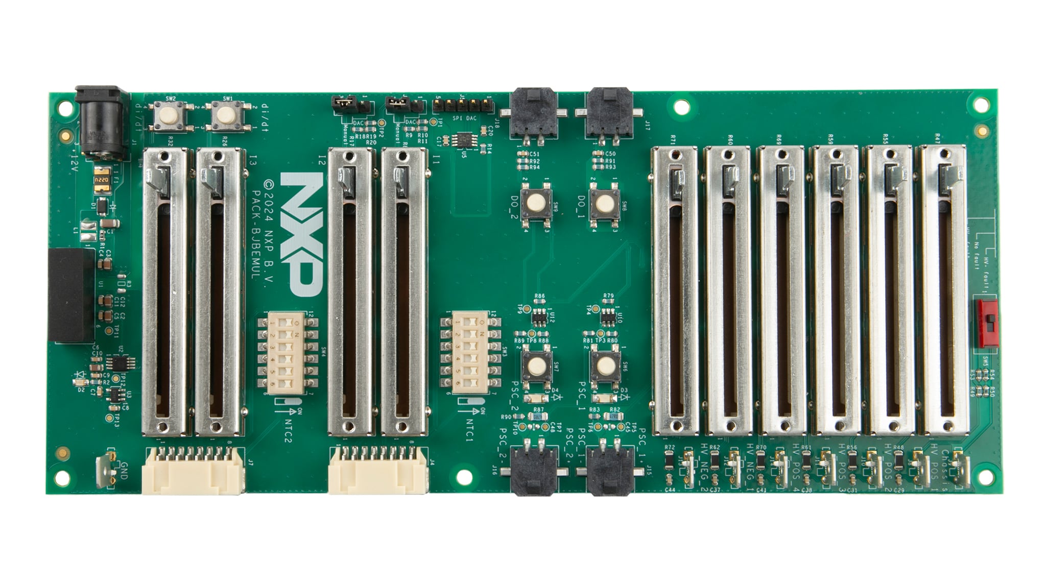
NXP provides battery junction box (BJB) integrated circuits (for example, the MC33777A). The PACK-BJBEMUL emulates different elements of a BJB (for example, high voltage, battery current, pyrotechnic switch) to ease the evaluation of the BJB devices.
3. Configure Hardware
3.1 Configure Hardware
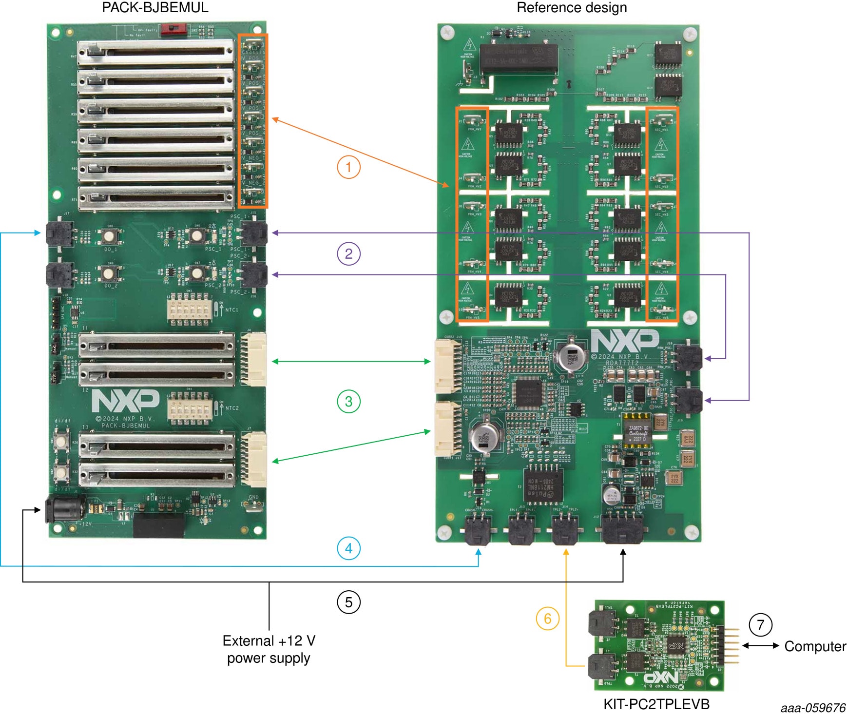
This section describes the typical setup to configure the PACK-BJBEMUL to evaluate the RDA777T2 reference design.
The RDA777T2 can measure the emulator current, voltage and temperature. It can also trigger the pyrotechnic switch emulation circuitry.
The setup shows a KIT-PC2TPLEVB board to interface the RDA777T2 with the computer via NXP software tools (for example, battery management system (BMS) ScriptGUI).
| Identifier | Description | Kit Content |
|---|---|---|
| 1 | Voltage measurement cable | Included in the kit |
| 2 | Pyrotechnic switch cable | Included in the kit |
| 3 | Current and temperature measurement cable | Included in the kit |
| 4 | Crash signal cable | Included in the kit |
| 5 | Power supply cable | Included in the kit |
| 6 | Electrical Transport Protocol Link (ETPL) communication cable | Included in the kit |
| 7 | USB to Universal Asynchronous Receiver/Transmitter (UART) cable | Included in the KIT-PC2TPLEVB kit |
| PACK-BJBEMUL | Battery junction box emulator | - |
| RDA777T2 | Battery junction box reference design | - |
| KIT-PC2TPLEVB | Communication board | - |
| Power supply | +12 V power supply | - |
Design Resources
Board Information
Additional References
In addition to our MC33777: Battery Junction Box Monitor IC page, you may also want to visit: