- Analog Toolbox
- Getting Started with the PCT2075DP-ARD Evaluation Board
Getting Started with the PCT2075DP-ARD Evaluation Board
Contents of this document
-
Get Started
-
Get to Know the Hardware
-
Install Software
-
Configure Hardware
Sign in to save your progress. Don't have an account? Create one.
Purchase your PCT2075DP-ARD Arduino® Shield - Temperature Sensors
1. Get Started
The NXP analog product development boards provide an easy-to-use platform for evaluating NXP products. The boards support a range of analog, mixed-signal and power solutions. They incorporate monolithic integrated circuits and system-in-package devices that use proven high-volume technology. NXP products offer longer battery life, a smaller form factor, reduced component counts, lower cost, and improved performance in powering state-of-the-art systems.
This page will guide you through the process of setting up and using the PCT2075DP-ARD evaluation board.
1.1 Kit Contents/Packing List
The PCT2075DP-ARD contents include:
- Assembled and tested evaluation board in an antistatic bag
- Quick Start Guide
1.2 Assumptions
Familiarity with the I²C-bus is helpful but not required.
1.3 Static Handling Requirements
This device is sensitive to ElectroStatic Discharge (ESD). Therefore, care should be taken during transport and handling. Use a ground strap or touch the PC case or other grounded source before unpacking or handling the hardware.
1.4 Minimum System Requirements
This evaluation board requires a Windows PC workstation. Meeting these minimum specifications should produce great results when working with this evaluation board.
- Computer with Windows 10
- One USB port (either 3.0, 2.0 or 1.1 compatible)
- One of three EVK boards (MIMXRT1050-EVK, LPC55S69-EVK, 8MMINILPD4-EVK) along with the associated firmware/GUI software
- USB cable for power and data connection between PC and EVK board (if not included in the EVK package)
2. Get to Know the Hardware
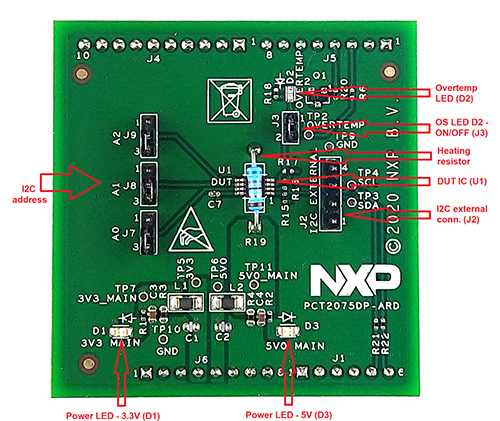
2.1 Board Features
- Connector for external access to I²C-bus
- Onboard heating resistor with ON/OFF control circuit
- Onboard LED for overtemperature signaling
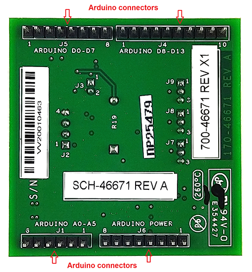
- Equipped with Arduino Uno R3 port for direct connection with Arduino devices
- Fully compliant with MIMXRT1050-EVK board, including GUI (Windows 10)
- Fully compliant with LPC55S69-EVK board, including GUI (Windows 10)
- Compliant with 8MMINILPD4-EVK board, including GUI (Windows 10)
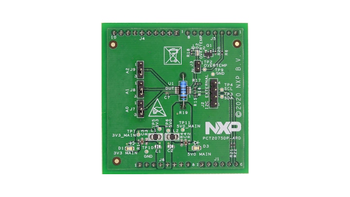
2.2 Board Description
The evaluation board is built around the PCT2075DP IC and works as an expansion board that can be connected through an Arduino port to various Arduino compatible (including original Arduino Uno R3) boards. The board is intended to test and measure the characteristics of the PCT2075DP 1 °C accuracy digital temperature sensor and thermal watchdog, produced by NXP Semiconductors.
Additionally, the expansion board has software support and a graphical user interface (Windows platform) for the following NXP evaluation boards: MIMXRT1050-EVK board, LPC55S69-EVK development board, and 8MMINILPD4-EVK board.
3. Install Software
3.1 Install Software
PCT2075DP-ARD evaluation board is designed and built as an expansion board able to work with a mother board equipped with an Arduino port. The board is built to be fully compatible with the following NXP evaluation boards:
The required firmware for the EVK boards is available for download at NXP. Before starting a pair of EVK and PCT2075DP-ARD, the EVK motherboard must be programmed with the corresponding firmware package. Additionally, a GUI application (Windows 10) is available for download from the same NXP site, allowing rapid testing and operation of the PCT2075DP-ARD expansion board through one of the EVKs. The GUI application is common for all three EVKs.
Once the software is installed, the first step is to select the correct combination of EVK/expansion board from the GUI, and then the board can be controlled from the GUI interface.
4. Configure Hardware
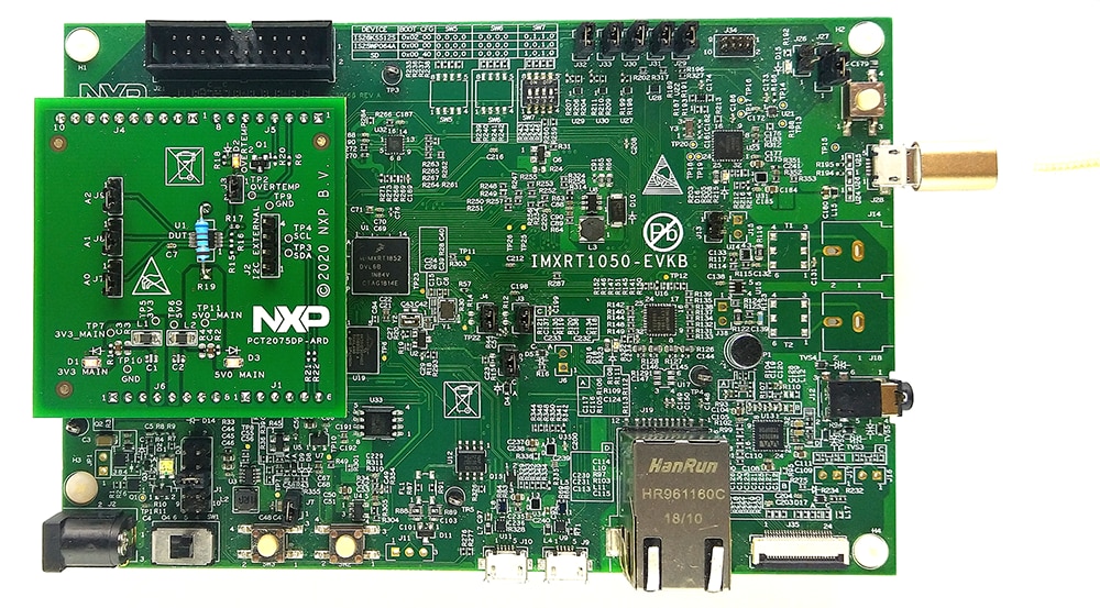
4.1 Using PCT2075DP-ARD with MIMXRT1050-EVK Board
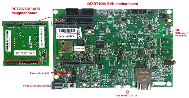
Figure 1 shows the required hardware for operation of the PCT2075DP-ARD expansion board with MIMXRT1050-EVK.
- One MIMXRT1050-EVK board
- One PCT2075DP-ARD expansion board
- One USB-A/USB Micro-B cable
- PC with Windows 10 operating system
The MIMXRT1050-EVK board can be powered through three different connectors:
- Using an external 5.0 V DC power supply, connected to
J2barrel power connector - Directly from a USB port through
J9USB Micro-B connector (J9) - From the same USB port through
J28connector
J28 can be used as a debug connector, therefore using J28, through the same USB cable, the EVK can be powered and in the same time linked to PC for data exchange.
The older USB ports (from PC) are not able to deliver the necessary current (500 mA), before establishing the communication, use an external power supply (connected to J2). From J1 (see Figure 1), the user can select the power configuration for the mother board. For more details, see i.MX RT1050 Evaluation Kit.
To configure the hardware and workstation, complete the following procedure:
- Configure the suitable power configuration of EVK (
J1). If the user is usingJ28for power supply, theJ1jumper is placed in position 5-6. If the user uses an external power supply (connected toJ2), the jumperJ1is placed in position 1-2 - Insert the PCT2075DP-ARD expansion card on the Arduino port of the EVK (see Figure 1)
- Connect the MIMXRT1050-EVK board using
J28connector to the USB port of the computer - Install the IMXRT1050 target firmware (download it from the NXP and see UM11581: Arduino Shields GUI and Firmware Installation User Guide for step-by-step instructions)
- Install GUI application on PC (see UM11581: Arduino Shields GUI and Firmware Installation User Guide )
- Open the GUI application to operate the device from the PC
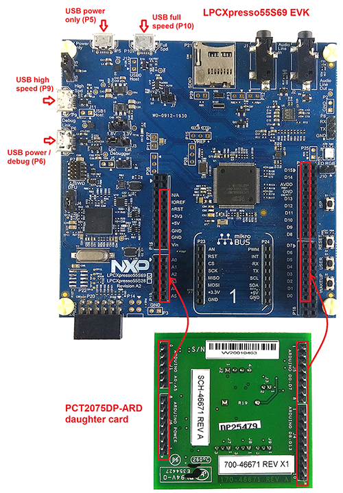
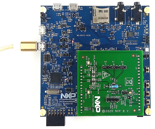
4.2 Using PCT2075DP-ARD with LPC55S69-EVK Board
Figure 3 shows the required hardware for operation of the PCT2075DP-ARD and LPC55S69-EVK board.
- One LPC55S69-EVK board
- One PCT2075DP-ARD expansion board
- One USB-A/USB Micro-B cable
- PC with Windows 10 operating system
The LPC55S69-EVK board is equipped with four USB Micro-B connectors: P5, P6, P9 and P10. The board can be powered through any USB port. Using P6 USB connector to connect the board to the PC, the bring-up operation is simplified because P6 is designated for debug and the USB cable will accomplish two tasks in the same time: powering the board, and data link between the EVK board and PC. For more details, see LPCXpresso55S69 Development Board.
To configure the hardware and workstation, complete the following procedure:
- Insert the PCT2075DP-ARD expansion card to
P16–P19connectors on LPC55S69-EVK development board (see the marked pinsP16–P19in Figure 3) - Connect the development board using port
P6USB port of PC - Install the LPCXpresso55S69 target firmware (download it from NXP and see UM11581 for step-by-step instructions)
- Install GUI application on PC (see UM11581: Arduino Shields GUI and Firmware Installation User Guide )
- Open the GUI application to operate the device from the PC
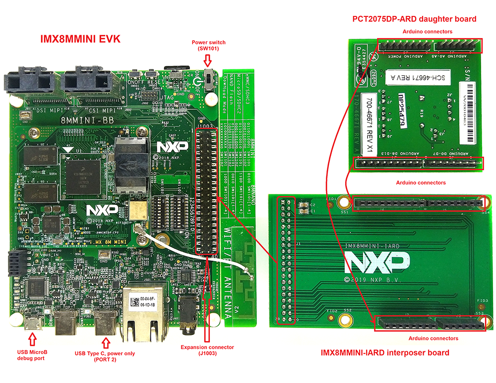
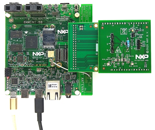
4.3 Using PCT2075DP-ARD with 8MMINILPD4-EVK Board
If 8MMINILPD4-EVK board is used for PCT2075DP-ARD operation, a third board (IMX8MMINI-IARD interposer board) must be used, especially designed and built as EVK – expansion board interconnection. The 8MMINILPD4-EVK is not equipped with an Arduino port; instead it has a 2 x 20 pin expansion connector J1003 (See 8MMINILPD4 - EVK User Manual). J1003 is a multipurpose port, containing different digital I/O lines, including specialized I²C and SPI buses. Starting from the expansion connector pin chart, an Arduino port interposer board was developed.
Figure 5 shows that, along with the EVK and expansion board, a third board is included in the setup assembly. To power up and operate the setup, it is also necessary to have one USB-C cable for power (see Figure 6), connected to Port 2 of the EVK board. The board is equipped with a power switch (SW101) which is positioned in ON position to power up the setup. Data communication is assured through a second (USB Micro-B) cable connected to the PC and debug port of the EVK (J901).
To attach the expansion board to the EVK, it is necessary to use the IMX8MMINI-IARD interposer boards by plugging PCT2075DP-ARD to the Arduino connector of the interposer, and then the interposer to expansion connector (J1003), on the i.MX 8M Mini EVK board (see Figure 5). The user may find more details regarding power up and operation of the setup assembly in the 8MMINILPD4-EVK User Manual and IMX8MMINI-IARD User Manual.
To configure the hardware and workstation, complete the following procedure:
- Insert the PCT2075DP-ARD on IMX8MMINI-IARD interposer board Arduino connectors (located on the top side)
- Attach the obtained assembly to EVK (plug
J1connector of IMX8MMINI-IARD, located on the bottom side intoJ1003expansion board, located on the top side of 8MMINILPD4-EVK board) - Power up the EVK board using a USB-Type C cable attached to Port 2
- Connect the EVK to the PC using a USB Micro-B cable, attached to
J901debug port - Place
SW101in ON position to power up the boards - Install the MIMXRT1050 target firmware (download it from NXP and see UM11581: Arduino Shields GUI and Firmware Installation User Guide for step-by-step instructions)
- Install GUI application on PC
- Open the GUI application to operate the device from the PC
4.4 Using PCT2075DP-ARD With Another Arduino Device
The PCT2075DP-ARD expansion board can be operated with different EVK boards, which has an Arduino port. There are two options to connect the board: using other EVK equipped with an Arduino port, and an EVK without an Arduino port.
In the first case, firmware is developed according to PCT2075 specifications, and then the PCT2075DP-ARD expansion board is attached to the EVK to operate the board.
In the second case, using the pin chart of Arduino connectors, make the necessary electrical connections (for power, I²C-bus and control lines), and develop the desired firmware compliant with IC specifications. Use PCT2075 data sheet to read details about internal registers of PCT2075 and data exchange between the internal controller and the EVK. Ensure that the electrical connections are accurate and avoid data conflicts on the signal lines to prevent IC damage.
Design Resources
Board Documents
Support
Forums
Connect with other engineers and get expert advice on designing with the PCT2075DP-ARD on one of our community sites.
On this page
- 1.1
Kit Contents/Packing List
- 1.2
Assumptions
- 1.3
Static Handling Requirements
- 1.4
Minimum System Requirements