Getting Started with the RDGD3160I3PH5EVB Reference Design
Contents of this document
-
Out of the Box
-
Get Hardware
-
Install Software
-
Configure Hardware
Sign in to save your progress. Don't have an account? Create one.
Purchase your RDGD3160I3PH5EVB
1. Out of the Box
The NXP analog product development boards provide an easy-to-use platform for evaluating NXP products. The boards support a range of analog, mixed-signal and power solutions. They incorporate monolithic integrated circuits and system-in-package devices that use proven high-volume technology. NXP products offer longer battery life, a smaller form factor, reduced component counts, lower cost and improved performance in powering state-of-the-art systems.
This page will guide you through the process of setting up and using the RDGD3160I3PH5EVB board.
1.1 Kit Contents and Packing List
The RDGD3160I3PH5EVB contents include:
- Assembled and tested RDGD3160I3PH5EVB (three-phase inverter populated with 5.0 V compatible gate driver devices) board in an anti-static bag
- Quick Start Guide
1.2 Additional Hardware
In addition to the kit contents, the following hardware is necessary or beneficial when working with this reference board.
- Microcontroller for SPI communication
- IGBT module Infineon HP Drive part FS820R08A6P2B
- DC link capacitor compatible with IGBT part FS820R08A6P2B
- HV power supply with protection shield and hearing protection
- Current sensors for monitoring each phase current
- 12 V, 1.0 A DC power supply
- High sample rate digital oscilloscope with probes
- High-voltage differential voltage probe
1.3 Windows PC Workstation
This reference design requires a Windows PC workstation. Meeting these minimum specifications should produce great results when working with this evaluation board.
- USB-enabled computer with Windows 8 or Windows 10
1.4 Software
Installing software is necessary to work with this reference design. All listed software is available on the information page at RDGD3160I3PH5EVB.
- S32S Design Studio IDE for power architecture
- Automotive Math and Motor Control Library (AMMCL)
- FreeMaster 2.0 runtime debugging tool
- Motor Control Application Tuning (MCAT)
- Example code, GD3160 Device Driver notes and GD31xx Device Driver Reference
2. Get Hardware
2.1 Board Features
- Capability to connect to HP Drive IGBT modules for full three-phase evaluation and development
- Daisy chain SPI communication (three high-side and three low-side gate drivers)
- Power supply which is a configurable jumper for VEE negative or GND reference
- Easy access power, ground and signal test points
- 2 × 2 32 PCIe socket for interfacing MCU control
- Optional connection for DC bus voltage monitoring
- Compatible with MPC5777C-DEVB, MPC5775BE-EVB, MPC5744P
2.2 Board Description
The RDGD3160I3PH5EVB is a fully functional three-phase inverter evaluation board populated with six GD3160 gate drivers with fault management and supporting circuitry. This board supports SPI daisy chain communication for programming and communication with three high-side gate drivers and three low-side gate drivers independently.
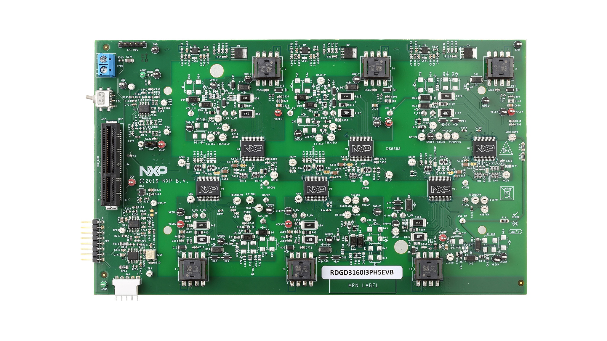
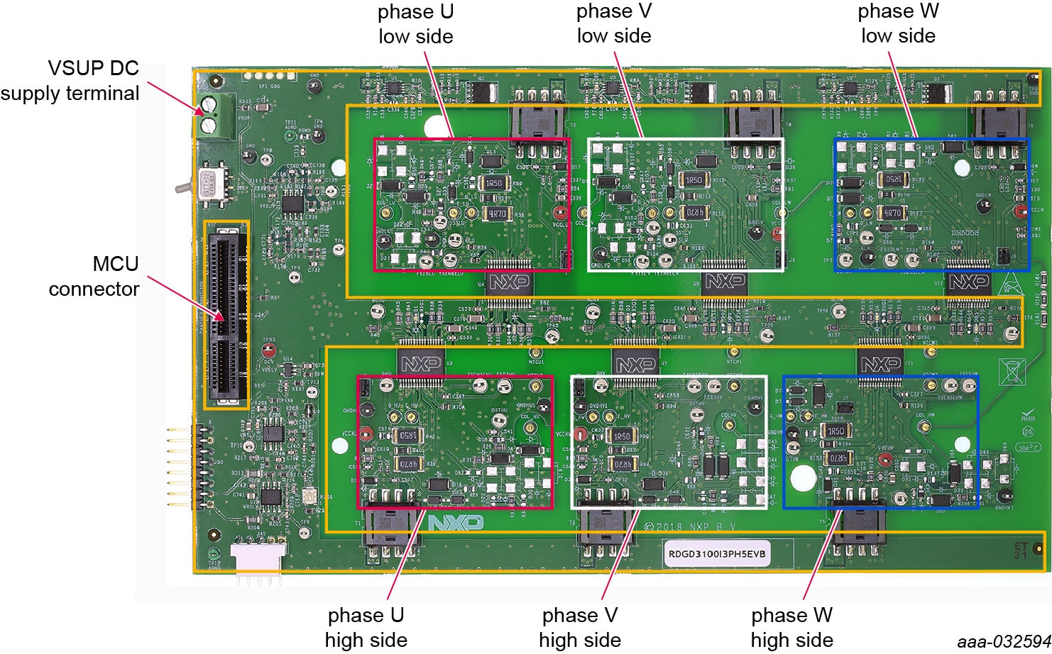
2.3 Board Components
Overview of the RDGD3160I3PH5EVB board.
3. Install Software
3.1 Software Development Tools
NXP has software development tools available for use with the NXP MPC5777C development board (DEVB). The development board is intended to provide a platform for easy customer evaluation of the MPC5777C microcontroller and to facilitate hardware and software development. The development board can be used for Powertrain/Inverters/BMS/Automotive Ethernet, etc. The latest product information is available at MPC5777C.
List of Development software:
- S32S Design Studio IDE for power architecture: The S32S design studio for power architecture IDE installed on a Windows PC workstation enables editing, compiling and debugging of source code designs. SDK supports several devices including MPC5777C. For more information, refer to S32DS- PA SDK for power architectures at the S32SDK-PA
- Automotive Math and Motor Control Library (AMMCL): Automotive Math and Motor Control Library (AMMCL) is a precompiled software library containing the building blocks for a wide range of motor control and general mathematical applications. For more information and to download AMMCL, refer to Automotive Math and Motor Control Library Set for MPC577xC at AUTOMCLIB
- FreeMaster 2.0 runtime debugging tool: FreeMASTER runtime debugging tool is a separate download and can also be used in conjunction with the MCU code developed with S32DS as a user-friendly real- time debug monitor, graphical control panel and data visualization tool for application development and information management. See FreeMASTER runtime debugging tool at FreeMaster
- Motor Control Application Tuning (MCAT): Motor Control Application Tuning (MCAT) is a FreeMASTER plug-in tool intended for the development of PMSM FOC and BLDC motor control applications. For more information and to download MCAT, refer to MCAT
- Example code, GD3160 Device Driver notes and GD3160 Device Driver Reference notes: GD3160 Device Driver example code REV1.2 provides a basis to get started and begin software development for the desired motor control. See GD3160 Device Driver Example Code (REV 1.2 or later) at GD3160-DRIVER
4. Configure Hardware
4.1 Configure the Hardware
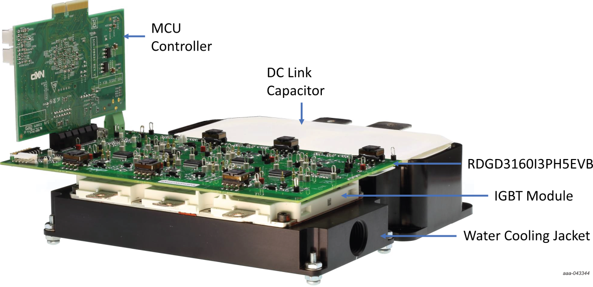
The following figure presents a typical hardware configuration.
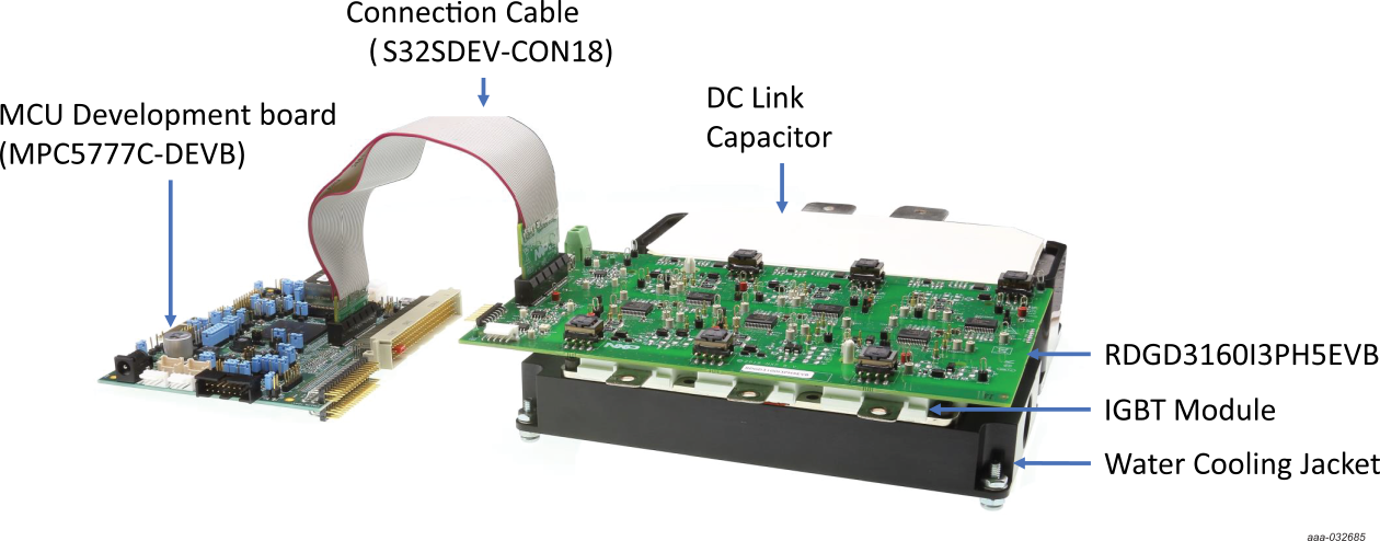
To configure the hardware, complete the following procedure:
- Assemble IGBT module with water cooling jacket if desired and properly attach to DC Link capacitor positive and negative high-voltage supply connections across U, V and W phases
- Attach RDGD3160I3PH5EVB to the IGBT module. Ensure that all board socket connection pins are properly seated onto the IGBT pin connections. The board socket pins are intended for easy attachment and detachment to IGBT module without damaging IGBT connection pins
- Connect Motor:
- Connect output of IGBT module each phase U, V and W to each of the respective U, V, W connections on the desired three-phase motor
- For running motor in closed loop motor control, connect resolver signals from motor resolver connection to the resolver pin connections on the
RDGD3160I3PH5EVB. See schematics for
J50header signal connections on the RDGD3160I3PH5EVB board - For running motor in closed loop motor control, connect current sensors from each phase U, V and W (current sensors are not
included with RDGD3160I3PH5EVB) and connect the respective signals from the current sensors to the phase current feedback pin connections
of the RDGD3160I3PH5EVB. See schematics for
J40header signal connections on the RDGD3160I3PH5EVB board
- Connect DC Power:
- Connect a low voltage DC power supply to the RDGD3160I3H5EVB at the VSUP connection terminal (12 V DC with a minimum 1.0 A supply).
Ensure that
J100jumper is in place - Connect a low voltage DC supply to MCU controller board and connect USB cable from MCU controller to desired computer for software driven motor control
- Connect high voltage/high current DC supply (use recommended voltage and current for desired motor) to positive and negative connections on DC Link capacitor to supply three-phase motor DC link voltage
- Connect a low voltage DC power supply to the RDGD3160I3H5EVB at the VSUP connection terminal (12 V DC with a minimum 1.0 A supply).
Ensure that
- Attach 2x32 PCIe cable (S32SDEV-CON18) supplied with kit to the RDGD3160I3PH5EVB and MCU controller board such as the MPC5777C-DEVB. This cable is keyed and is compatible with interface port on MPC5777C-DEVB
Design Resources
Board Information
Additional References
In addition to our GD3160: Advanced Single-Channel High-Voltage Isolated Automotive Gate Driver for SiC MOSFETs/IGBTs page, you may also want to visit:
Gate Driver Pages
- GD3100 | Single-Channel Gate Driver for IGBTs/SiC MOSFETs
- GD3160 | Advanced High Voltage Isolated Gate Driver with Segmented Drive for SiC MOSFETs
Application Pages
Tool Pages
Hardware Pages
Software Pages
Support
Forums
Connect with other engineers and get expert advice on designing with the RDGD31603PHSEVM on one of our community sites: Power Management Community .