MCU Board Quick Setup for Autos
Contents of this document
-
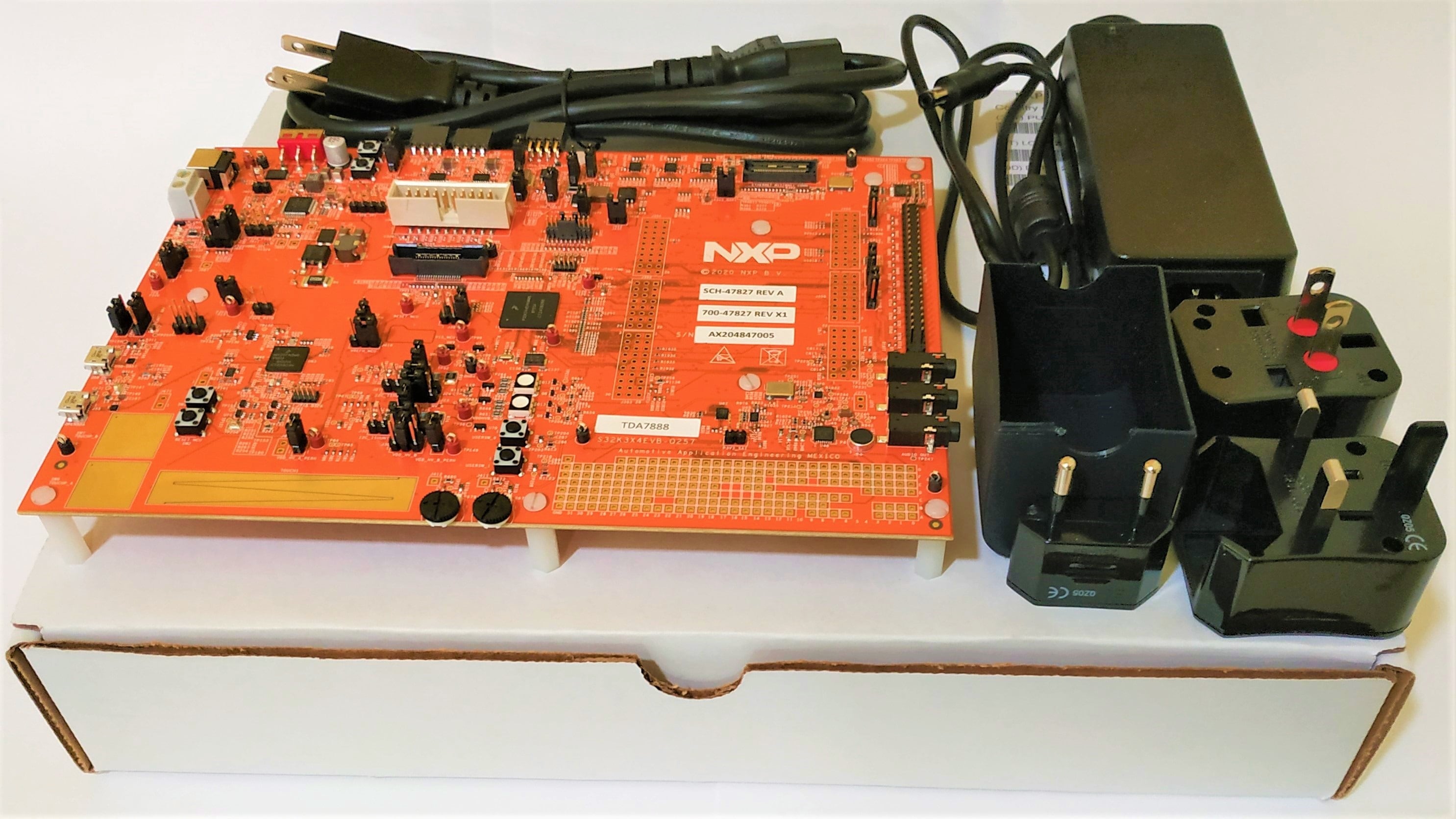
Out of the Box
-
Get Software
-
Plug It In
-
Build
Sign in to save your progress. Don't have an account? Create one.
Purchase your S32K3x4-Q257 Full-Featured General Purpose Development Board
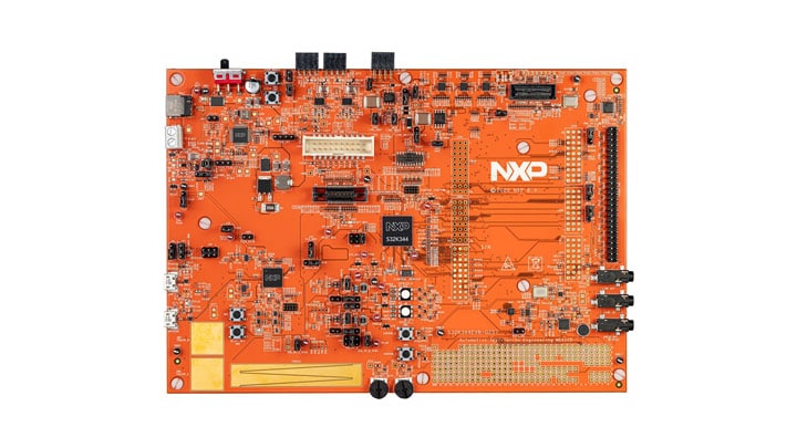
1. Out of the Box
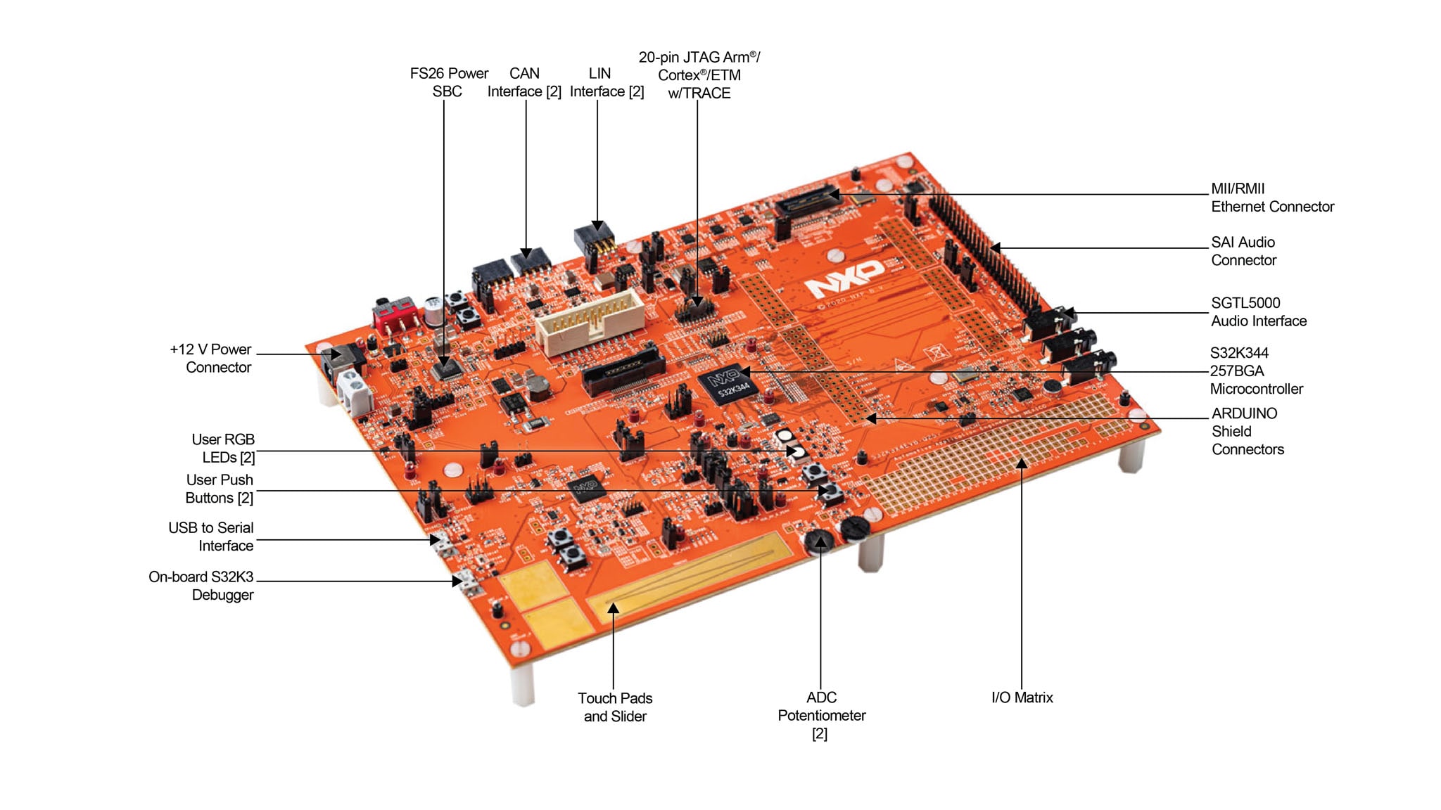
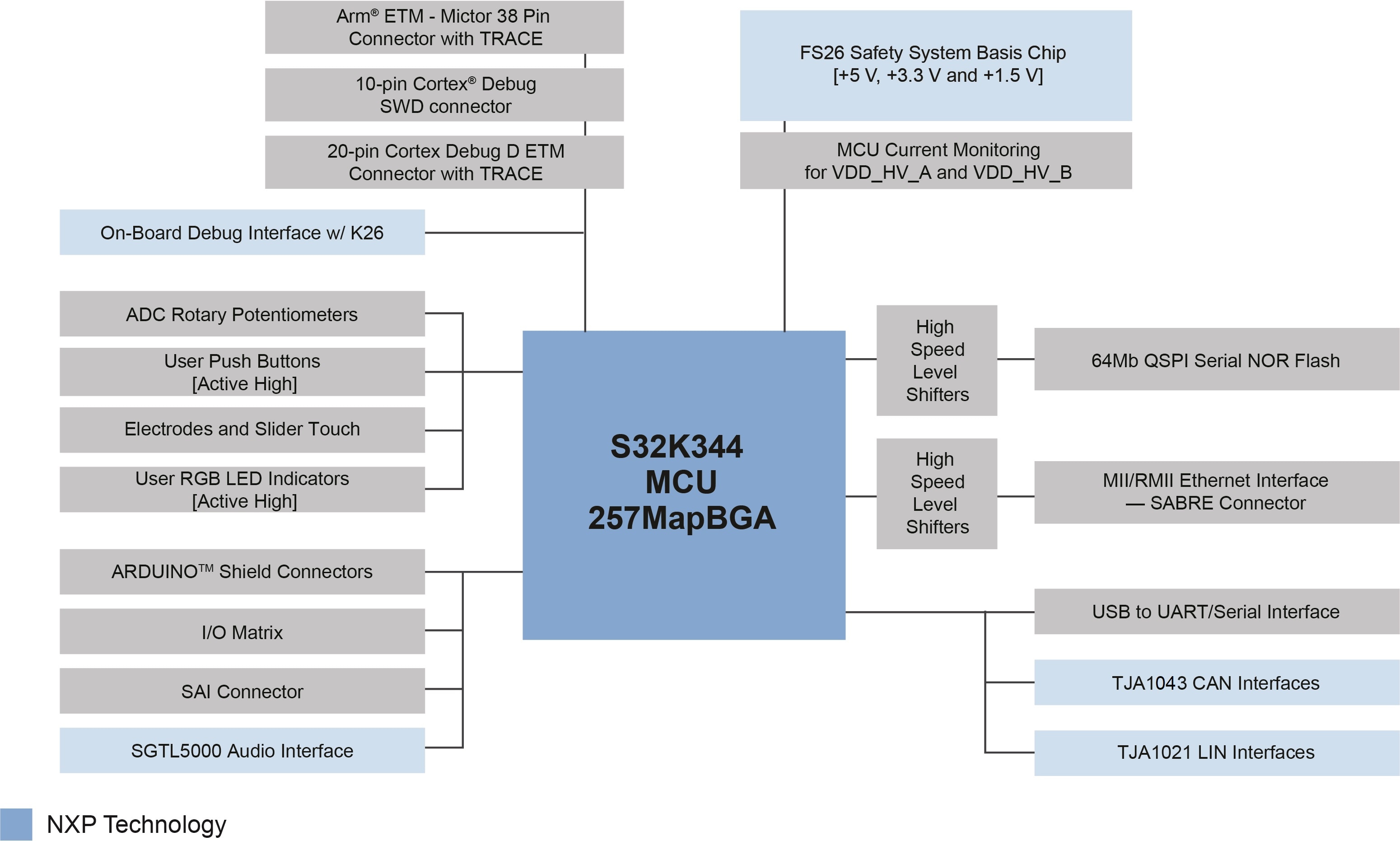
1.1 Get to Know the S32K344EVB-Q257 Evaluation Board
2. Get Software
You can watch the video or follow the step-by-step guide below to set up your S32K3X4EVB-Q257 evaluation board.
2.1 Get the Integrated Development Environment (IDE)
Download and Install S32 Design Studio IDE for S32 Platform.
DOWNLOAD S32 DESIGN STUDIO IDE
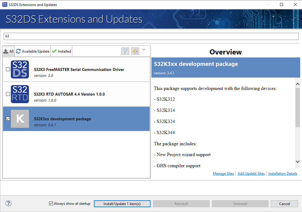
2.2 Install the S32K3xx Development Package
Go to Help → S32DS Extensions and Updates from the top menu to open the S32DS Extensions and Updates. Navigate to the S32K3xx development package and install it.
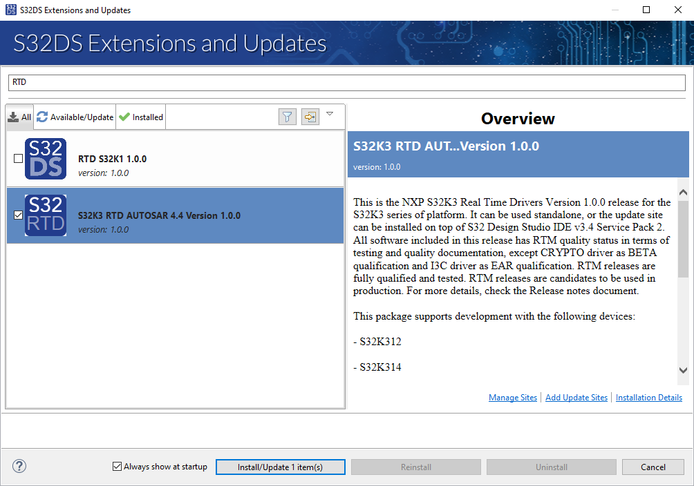
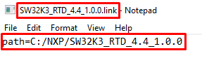
Continue with the installation of the Real-Time Drivers for S32K3xx:
2.3 Download and Install Elektrobit Tresos Studio and Real-Time Drivers (Only AUTOSAR® Users)
Download and install Elektrobit Tresos Studio / AUTOSAR Configuration Tool from S32K3 Standard Software Package.
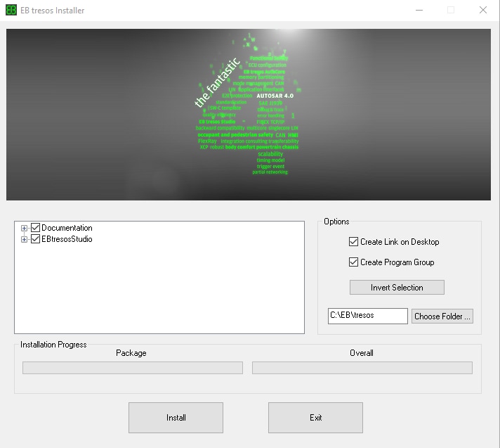
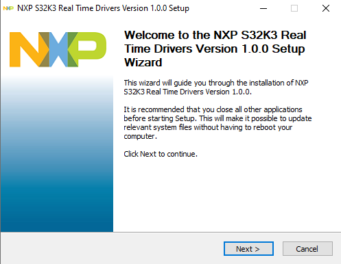
Download and install the .exe file of the S32K3 Real-Time Drivers for Cortex-M from the S32K3 Standard Software Package.
The installer will ask for the EB Tresos installation directory on your disk, saving time in configuration.
2.4 Get the Run-Time Debugging Tool
S32K3X4EVB-Q172 performs better when using the FreeMASTER Run-Time Debugging Tool.
The FreeMASTER communication driver for S32K3 microcontrollers is also needed; download it from the Automotive SW - S32K3 - S32 FreeMASTER link in the S32K3 Standard Software Package.
3. Plug It In
3.1 Set Up Jumpers in the S32K3X4EVB-Q257 Evaluation Board
| Default Power-Supply Jumper settings | ||
|---|---|---|
| Jumper | State | Notes |
J13 |
CLOSED | 5 V from FS26 SBC |
J16 |
CLOSED | 3.3 V from FS26 SBC |
J23 |
2-3 | 3.3 V for the VDD_HV_A domain |
J24 |
2-3 | 3.3 V for the VDD_HV_A domain |
J25 |
CLOSED | Shunts for A current measurement bypassed |
J29 |
2-3 | 1 Ohm shunt for B current measurement |
J30 |
5-6 | VDD_HV_A_MCU is routed to VDD_HV_B domain |
J31 |
CLOSED | Shunts for B current measurement bypassed |
J321 |
1-2 | IOREF and AREF at Arduino routed to VDD_HV_A domain |
J360 |
5-6 | V15 domain powered from external NPN ballast transistor |
J37 |
2-3 | V15 NPN ballast transistor powered from VDD_HV_B domain |
J374 |
CLOSED | External circuits powered from VDD_HV_A domain |
J375 |
CLOSED | External circuits powered from VDD_HV_B domain |
J410 |
1-2 | The ADC reference is routed to the VDD_HV_A domain. |
J685 |
1-2 | Select voltage level for FS26 DEBUG pin |
J686 |
CLOSED | Disabled FS26 watchdog after power-up |
| Default Peripherals Jumper settings | ||
|---|---|---|
| Jumper | State | Notes |
J57 |
1-2 | USB to Serial IC powered from 5 V |
J60 |
2-3 | USB to Serial IC Reset pin routed to voltage divider |
J61 |
CLOSED | Ethernet connected to VDD_HV_B_PERF domain |
J62 |
CLOSED | Ethernet Connected to 3.3 V |
J65 |
CLOSED | QSPI flash powered from 3.3 V |
J402 |
CLOSED | QSPI signals level refers to VDD_HV_B_PERF domain |
J390 |
CLOSED | LIN1 Transceiver enabled |
J674 |
2-3 | LIN1 Controller mode via INH pin |
J678 |
CLOSED | LIN2 Transceiver enabled |
J679 |
2-3 | LIN2 Controller mode via INH pin |
J413 |
CLOSED | CAN0 Transceiver enabled |
J672 |
CLOSED | CAN1 Transceiver enabled |
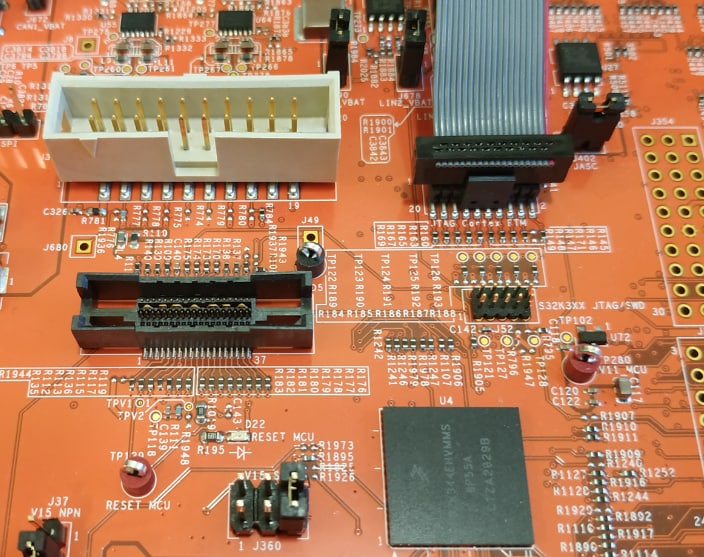
3.2 Plug in the Power Supply
Switch SW10 to the OFF position (fully to the right).
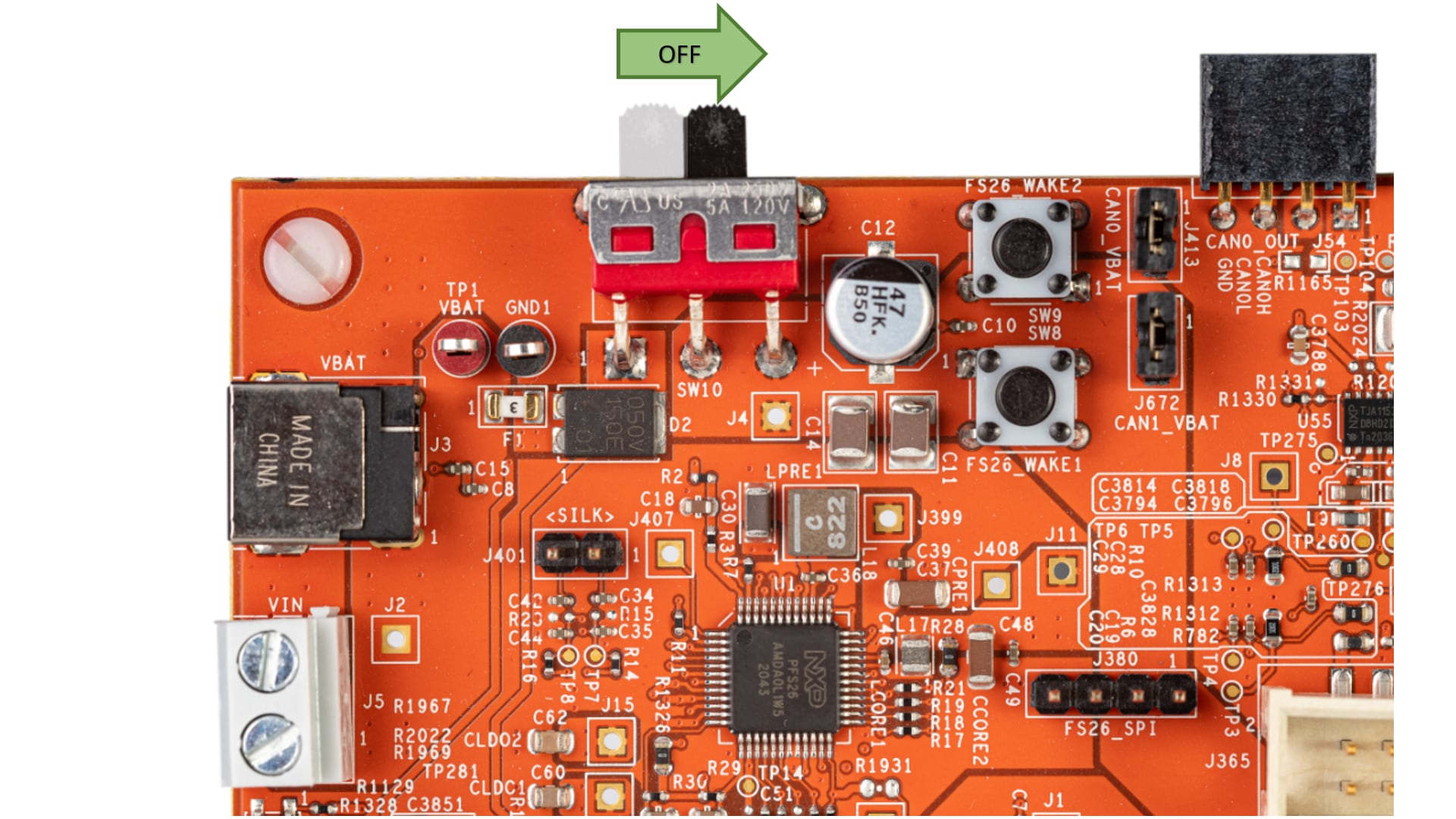
Connect the 12 V power supply adapter and then switch
SW10 to the ON position (fully to the left).
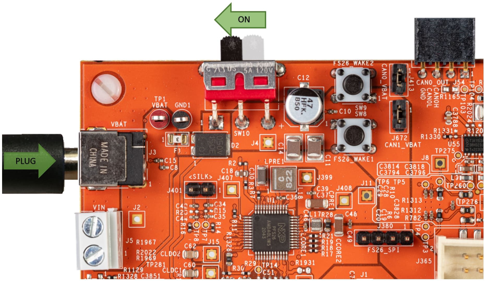
This power-up procedure manage that SBC starts with the disabled watchdog. Four orange LEDs indicate active 12 V, 5 V, 3.3 V and 1.5V power supply domains.
3.3 Connect the Debugger Cable
Connect a micro-USB cable to the J55 connector to debug via the on-board S32K3 debugger.
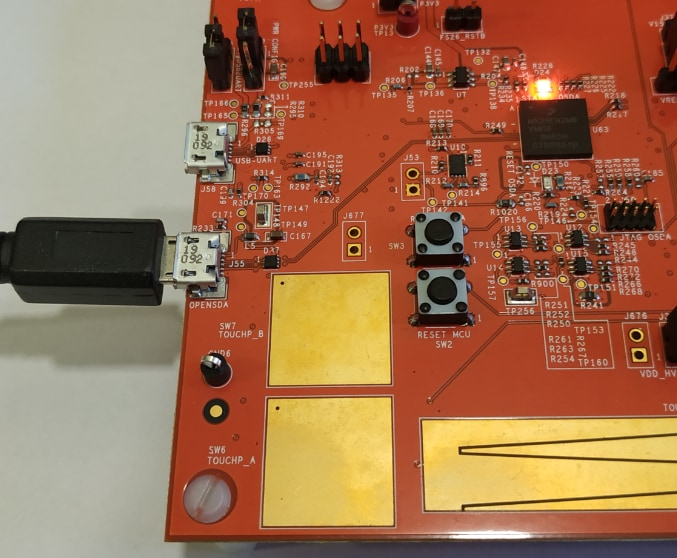
Or use one of the available JTAG connectors to debug via the external S32K3 debugger.
4. Build
Let's take your S32K3X4EVB-Q257 Evaluation Board for a test drive.
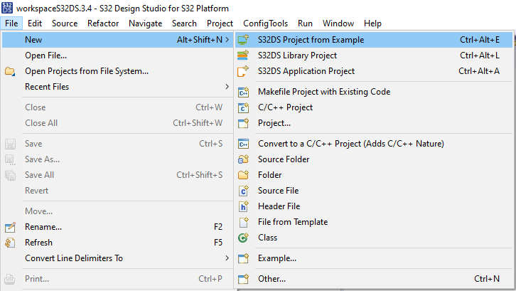
4.1 Create a S32DS Project from Example
Open S32DS and from the menu, go to: File → New → S32DS Project from Example. Select one of RTD example codes. You may choose between examples with high-level API or with low-level API. For example: Port_example_K344.
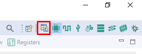
4.2 Using the Configuration Tool
Double-click on the .mex project file.
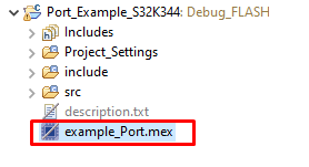
Please unsure that you configure appropriate project and click on "Update Code" button for generating configuration files.

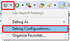
4.3 Upload Software and Debug
Return back to the C/C++ perspective.
Use Debug Configuration menu and select one of predefined debug configurations for building and uploading software into MCU.
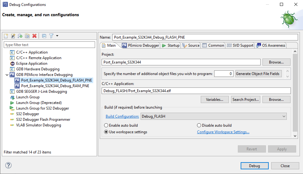
The S32DS will switch into Debug perspective where you may let the code run.
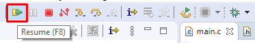
The red LED will now blink for approximately 10 seconds.
Design Resources
Board Information
- S32K3X4EVB-Q257 Evaluation Board - HW User Manual
- S32K3X4EVB-Q257 Evaluation Board - REV A Schematics
- S32K3 MCUs for General Purpose - REV A Hardware Design Package
- S32K3X4EVB-Q257 Evaluation Board - REV A Design Files
- S32K3X4EVB-Q257ND Evaluation Board - REV B CAD Files
- S32K3X4EVB-Q257 Evaluation Board - REV A Layout
Chip Documents
Support
Training
Forums
Connect with other engineers and get expert advice on designing with the S32K3X4EVB-Q257 evaluation board using our community sites.
On this page
- 2.1
Get the Integrated Development Environment (IDE)
- 2.2
Install the S32K3xx Development Package
- 2.3
Download and Install Elektrobit Tresos Studio and Real-Time Drivers (Only AUTOSAR® Users)
- 2.4
Get the Run-Time Debugging Tool