Getting Started with the SAF8544 Pluto Sensor - Radar Reference Design
Contents of this document
-
Out of the Box
-
Get to Know the Hardware
-
Operating Pluto Sensor
Sign in to save your progress. Don't have an account? Create one.
Purchase your PLUTO-SENSOR
1. Out of the Box
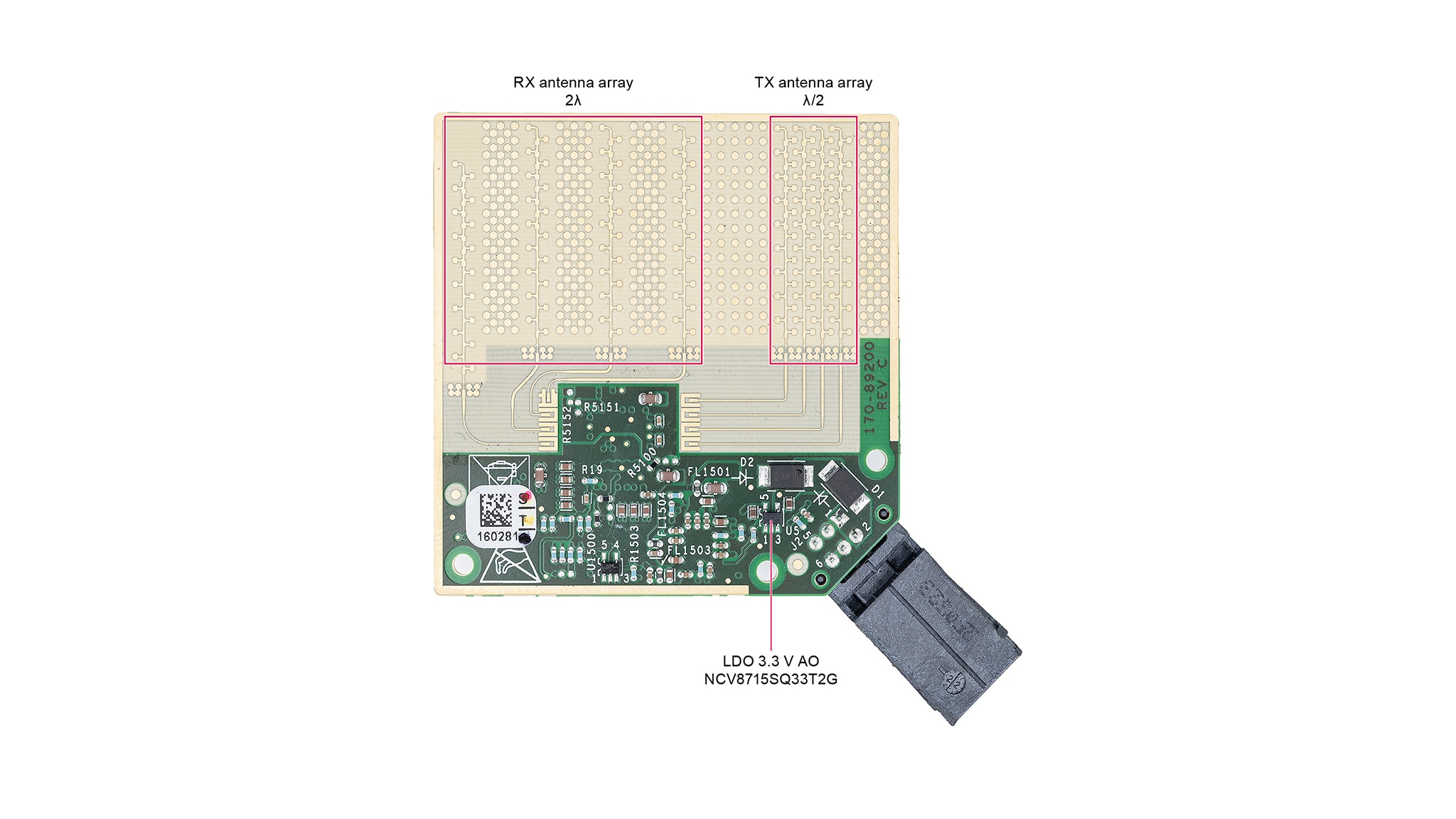
The NXP Pluto sensor is a corner radar application based on the Radio Frequency Complementary Metal-Oxide Semiconductor (RFCMOS) System-on-Chip (SoC) SAF8544. This application contains printed antenna reference planes. The antenna array consists of four sections with 10 antenna patch elements per section on either side of the SoC. One antenna plane dedicated for the SoC transmit antenna plane and one for the received antenna plane. The transmitter (Tx) and receiver (Rx) antenna feeding structures on the PCB are routed to ensure equal electrical path lengths. The spacing between two consecutive antenna array structures is 2*λ (Receive antenna plane) and λ/2 (Transmit antenna plane) with grounded patterns in between each consecutive antenna array.
1.1 Kit Content and Packing List
- Pluto sensor, 1 pc
- Power / Automotive Ethernet cable, 1 pc
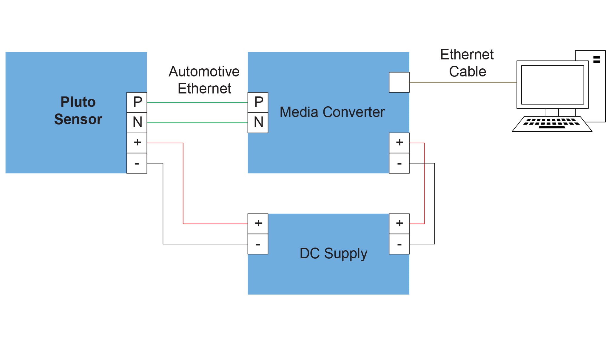
The evaluation kit comes with the Pluto sensor itself and a Power/Automotive Ethernet cable. Additionally, a media converter is required in the setup to enable full-duplex 1 Gbit communication between automotive Ethernet (1000BASE-T1) and standard Ethernet (1000BASE-T), as they utilize different physical layer specifications and cable types (single-pair vs. four-pair twisted cables).
1.2 ESD Warning
CAUTION
This device is sensitive to ElectroStatic Discharge (ESD). Therefore care should be taken during transport and handling. You must use a ground strap or touch the PC case or other grounded source before unpacking or handling the hardware.
2. Get to Know the Hardware
2.1 Salient features
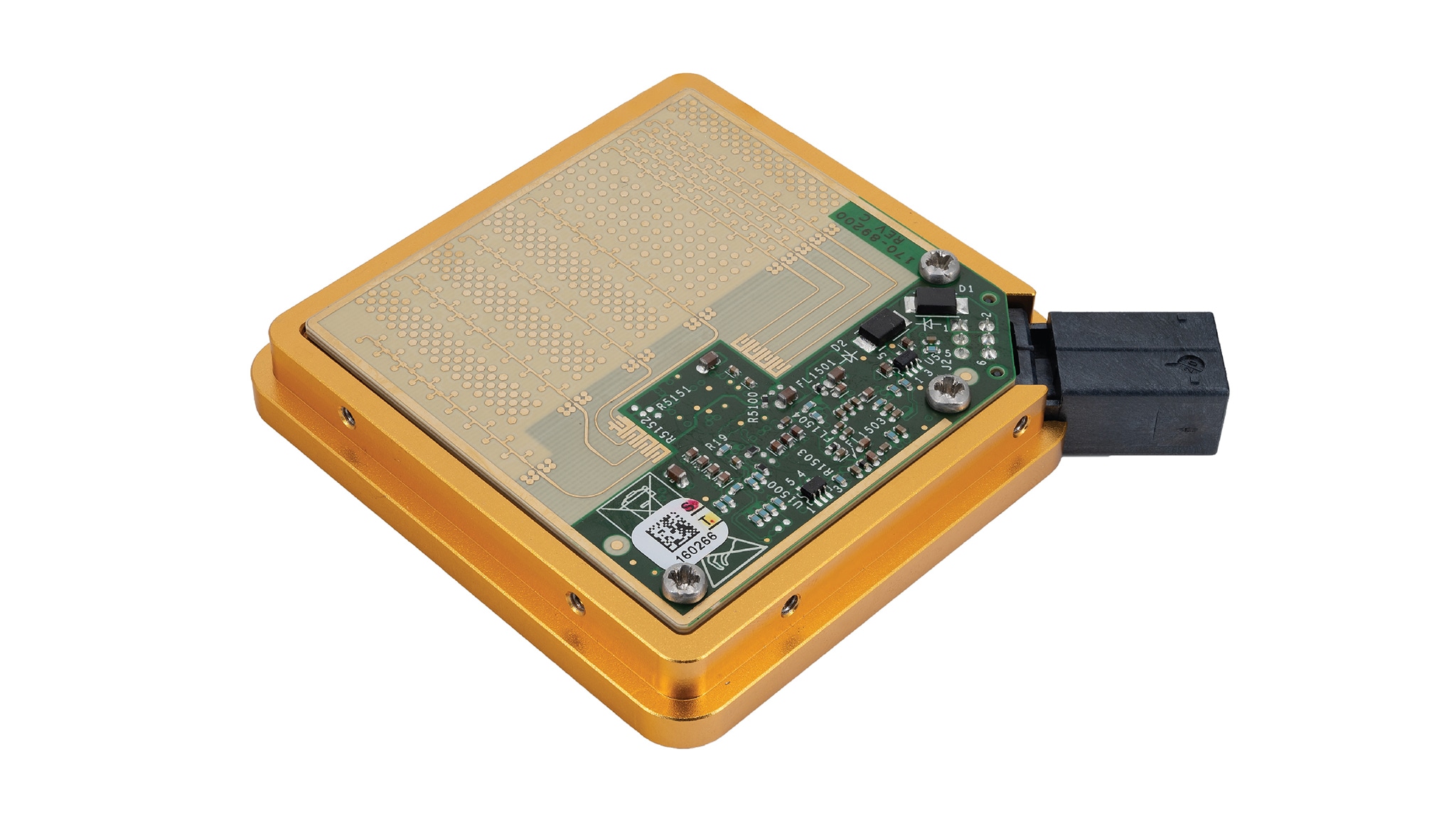
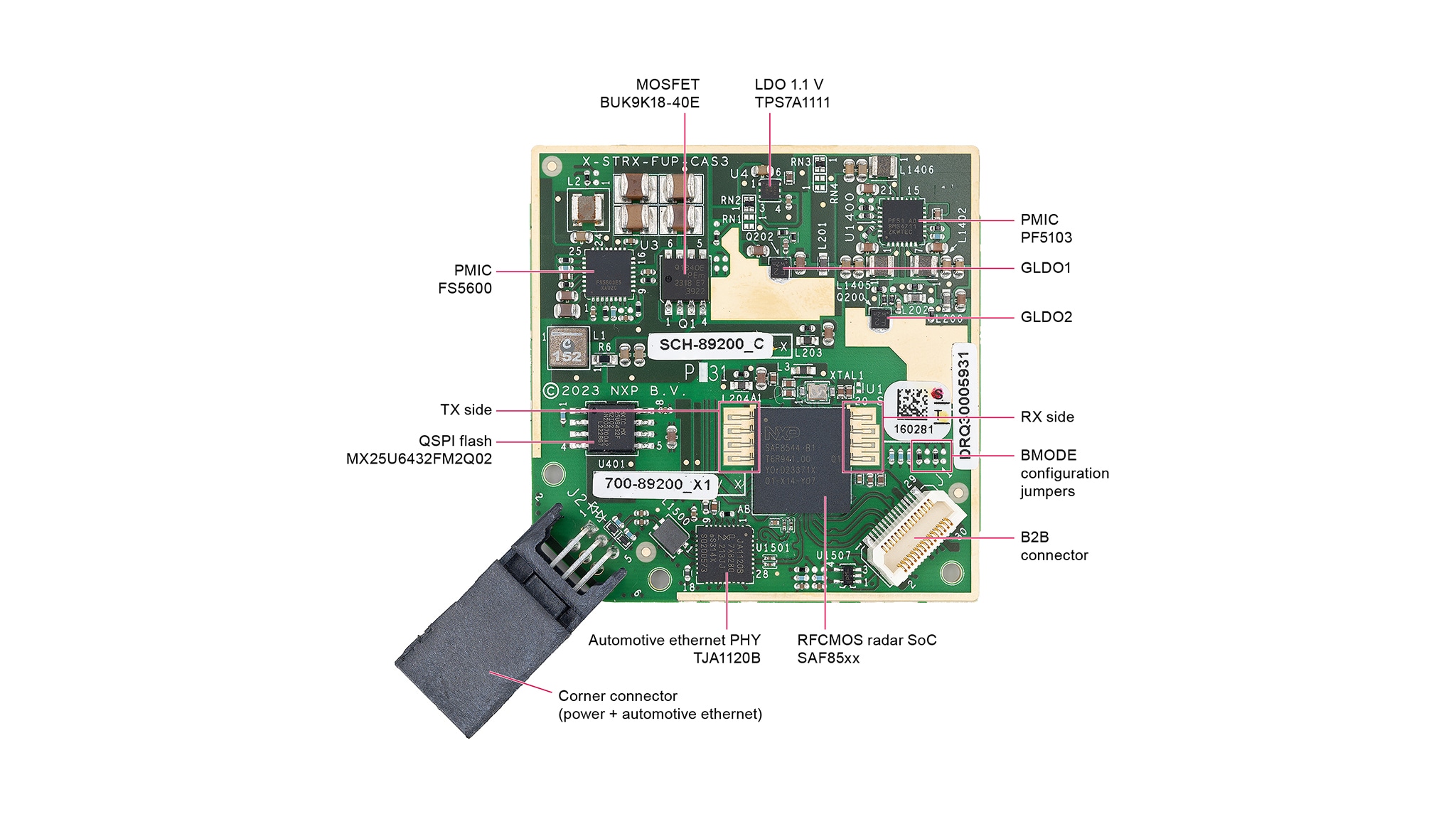
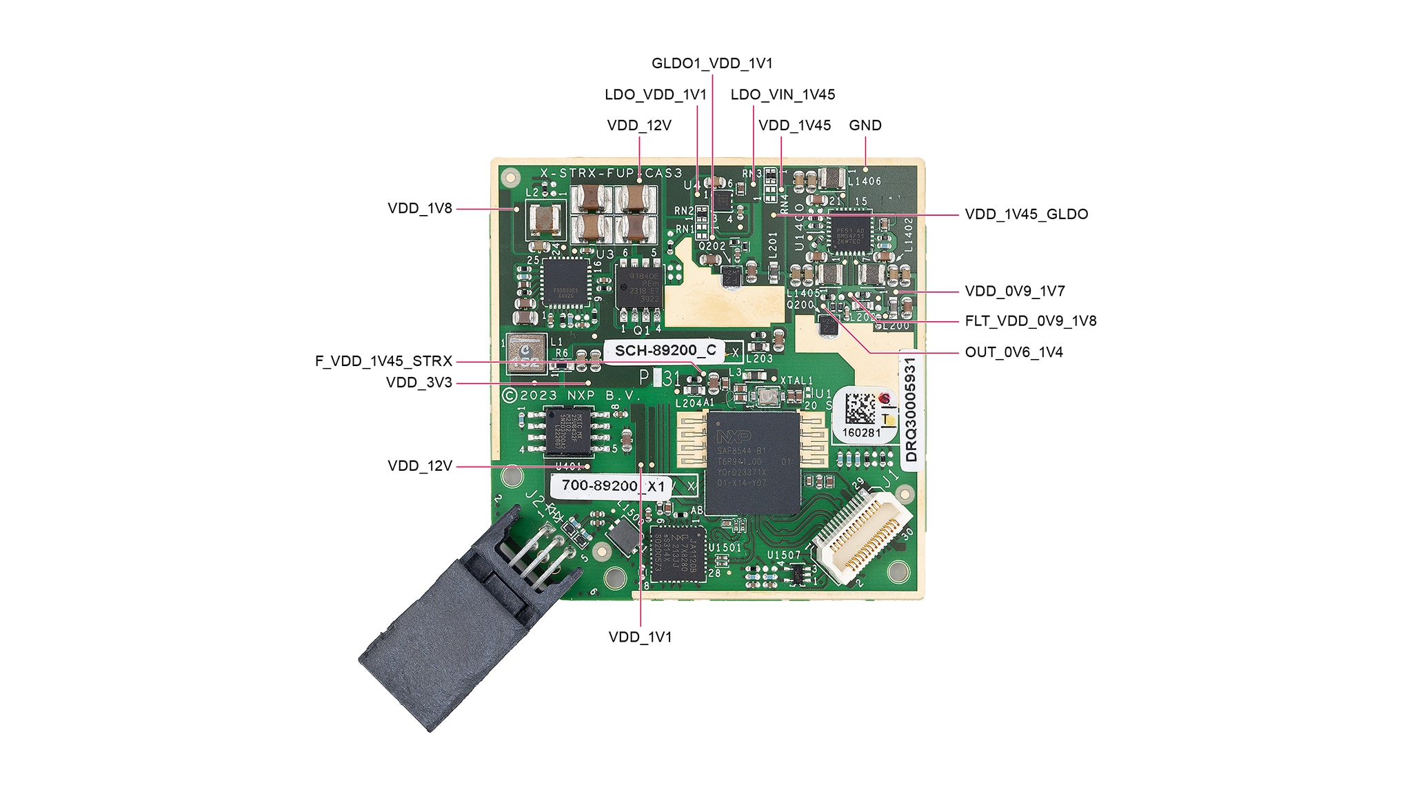
The salient features of the Pluto board are presented in the figure below. The radar sensor contains the SAF8544 28 nm RFCMOS SoC, Automotive Ethernet PHY TJA1120B, two power-management integrated circuits (PMIC) FS5600 and PF5103, global low-dropout regulator 1 (GLDO1) for RX chain and GLDO2 for TX chain, flash memory, LDO for 1.1 V. The Corner connector provides supply voltage 12 V, automotive ethernet interface and ground pins. The Board-to-Board Connector (B2B Connector) provides supply voltages 1.8 V for digital domain and 3.3 V for analog domain, and also connection with JTAG, CSI and I²C-bus interfaces.
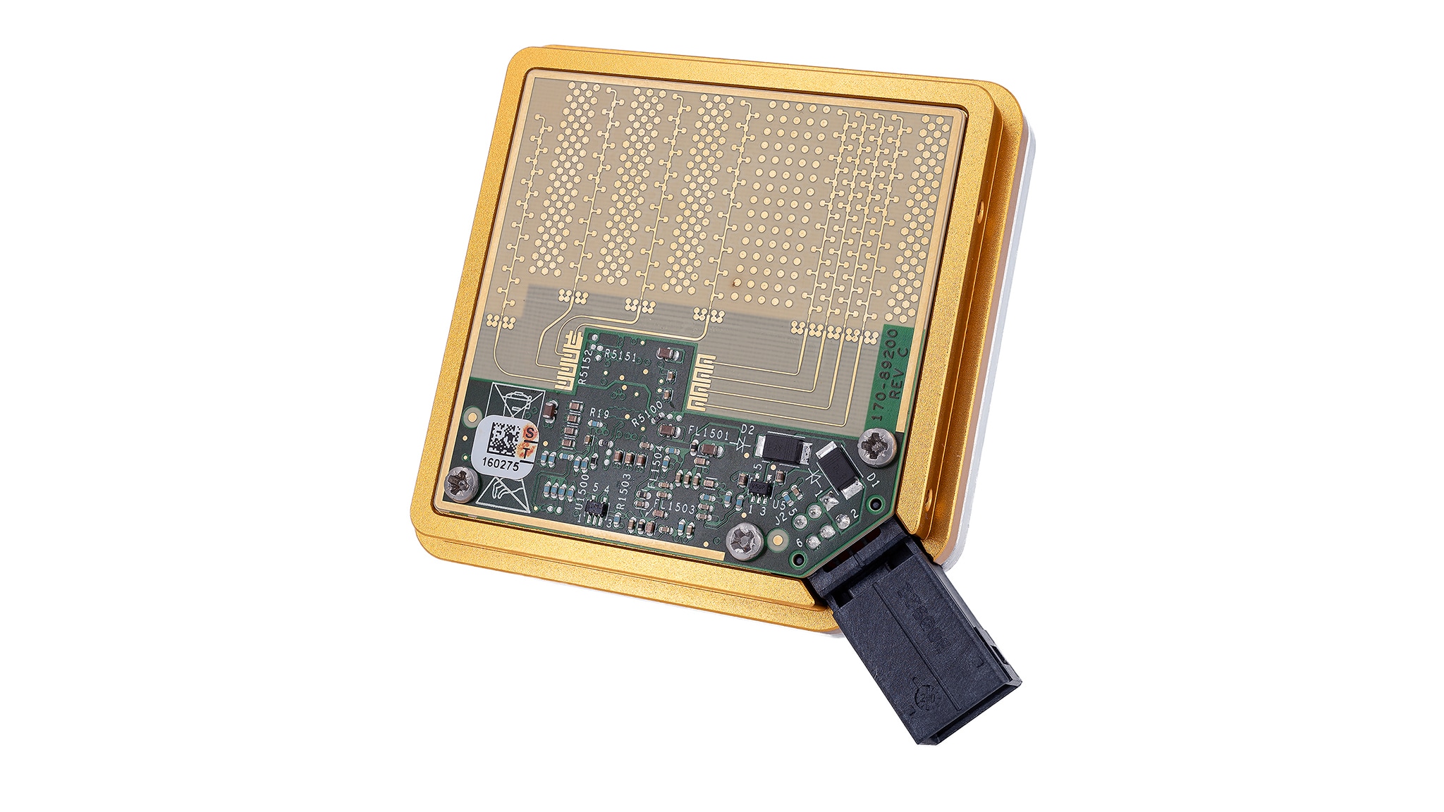
The top side of Pluto board contains the RX and TX antenna arrays. RX antenna array is represented by four receive antenna elements that feature 2λ spacing, whereas the four transmit antennas have λ/2 spacing. More information about antenna arrays and their characteristics is given in UM11963 SAF8544 reference design user manual - Pluto sensor. The antenna side of the Pluto board is shown in the figure below.
2.2 Block Diagram
The block diagram presented in this section describes the main power connection of Pluto board. This radar application is powered up using 12 V input voltage, which is filtered by a RP diode. The 12 V supplies both an LDO that generates an always-on 3.3 V and the NXP PMIC FS5600.
The output of FS5600 is the 1.8 V generated by Buck1 and 3.3 V generated by Buck2. The 1.8 V voltage is mainly used for powering up input-output (IO) digital domain, whereas the 3.3 V voltage is used as an input voltage for NXP PMIC PF5103, for NXP TJA1120B Automotive Ethernet PHY, for MBB interface and for powering SAF8544.
The NXP PMIC PF5103 consists of three internal Buck converters, i.e. Buck1, Buck2, Buck3 and two internal LDOs, which are not used in current application. Buck1 output generates a stable 0.9V that supplies SAF8544 digital core. Buck2 is able to generate a voltage in the range of 0.9 V - 1.7 V that feeds the SAF8544 TX domain either through the GLDO2 BJT or through an LRC filter. Buck3 generates 1.45 V that is used to supply SAF8544 RF Power RX domain through an LRC filter. Additionally, Buck3 is connected to the TJA1120B either through GLDO1 BJT or LDO to generate a stable 1.1 V voltage.
2.3 Pluto Board Test Point
Various test points are provided as reference points for a number of measurements. Voltage measurements are performed with high precision digital multimeters connected to the corresponding testing points available for the different voltages on the board. The description of testing points on the board is given in the image of this section.
Note: It is essential to mention that these voltages shall be measured in respect to a common reference ground in order to keep the correct electrical potential difference. There are various reference ground points on the board (see relevant schematics of Pluto board).
| Testing Point | Description |
|---|---|
| VDD_12V | Test Point for 12 V Input Voltage |
| VDD_3V3 | Test Point for 3V3 Analog Voltage |
| VDD_1V8 | Test Point for 1V8 Digital Voltage |
| VDD_0V9 | Test Point for Buck1 0V9 Output Digital Voltage |
| VDD_0V9_1V7 | Test Point for Buck2 0V9 - 1V7 Output Voltage |
| VDD_1V45 | Test Point for Buck3 1V45 Output Voltage |
| FLT_VDD_0V9_1V8 | Test Point for LRC Filter 1V3 Output Voltage (SAF85xx RF Power (RX) 1V45 Input Voltage) |
| F_VDD_1V45_SAF85XX | Test Point for SAF85xx RF Power (RX) 1V45 Input Voltage |
| OUT_0V6_1V4 | Test Point for GLDO2 1V3 Output Voltage (SAF85xx RF Power (TX) 1V3 Input Voltage) |
| VDD_1V45_GLDO | Test Point for GLDO1 1V45 Input Voltage |
| GLDO1_VDD_1V1 | Test Point for GLDO1 1V1 Output Voltage |
| LDO_VIN_1V45 | Test Point for LDO 1V45 Input Voltage |
| LDO_VDD_1V1 | Test Point for LDO 1V1 Output Voltage |
| GND | Test Point Ground |
3. Operating Pluto Sensor
3.1 Connecting the Sensor
The block diagram shown in the figure below presents the connection scheme of Pluto sensor with a PC through a media converter, which converts the automotive ethernet to a standard ethernet and provides 1000 Mbit full-duplex communication. A DC Power Supply able to provide dual 12 V is used to power up both the Pluto sensor and a media converter.
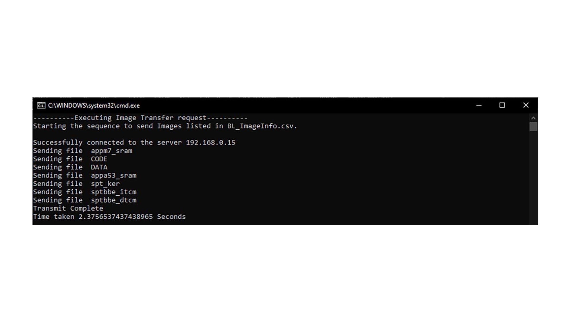
3.2 Operating Network Bootloader
The Pluto sensor comes with the Network Bootloader flashed inside. One can create a download package if necessary. Refer to UM11889 Network bootloader user manual to do so. In order to use demo radar FW, the SAF85xx Radar Integration SW package should be downloaded from nxp.com. That contains the prepared package of radar demo FW that can be loaded inside the Pluto sensor through Ethernet:
- Power up the radar sensor, connect the automotive Ethernet cables to the media converter, and the media converter to the PC with the ethernet cable, Figure XX
- Check network connection settings at the operating PC, i.e. the IP address is set to address “192.168.0.XX”, where “XX” is any number except “01” or “15”. Note that addresses “192.168.0.15” and “192.168.0.01” are reserved for Pluto and gateway, respectively
- Navigate to the network bootloader package (folder) inside of the downloaded SAF85xx Radar Integration SW package
- Run the batch file (.bat)
The radar FW can be used with the Radar Xplorer that is also included in the SAF85xx Radar Integration SW package.