- Analog Toolbox
- Getting Started with the TEA2376DB1602 Demo Board
Getting Started with the TEA2376DB1602 Demo Board
Contents of this document
-
Out of the Box
-
Get Hardware
-
Get Software
-
Configure Hardware
Sign in to save your progress. Don't have an account? Create one.
Purchase your TEA2376DB1602
1. Out of the Box
The NXP analog product development boards provide an easy-to-use platform for evaluating NXP products. The boards support a range of analog, mixed-signal and power solutions. They incorporate monolithic integrated circuits and system-in-package devices that use proven high-volume technology. NXP products offer longer battery life, a smaller form factor, reduced component counts, lower cost and improved performance in powering state-of-the-art systems.
This page will guide you through the process of setting up and using the TEA2376DB1602 300W interleaved PFC demo board.
1.1 Kit Contents and Packing List
The contents of the TEA2376DB1602 kit are:
- TEA2376DB1602 300 W interleaved PFC demo board
1.2 Additional Hardware
In addition to the kit contents, the following hardware is necessary or beneficial when working with this kit.
RDK01DB1563 USB-I²C Programming Interface
1.3 Required Equipment
- AC mains source
- Power analyzer (optional)
- Electronic load (500 V, 1 A)
- Oscilloscope for observing operation behavior
- Windows PC with USB for parameter modifications via software and interface
- USB-I²C programming interface (RDK01DB1563 kit, optional)
1.4 Windows PC
- PC with Windows operating system
- Ringo TEA2376 software
2. Get Hardware
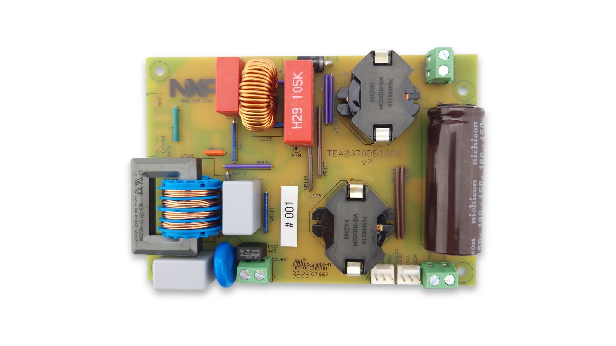
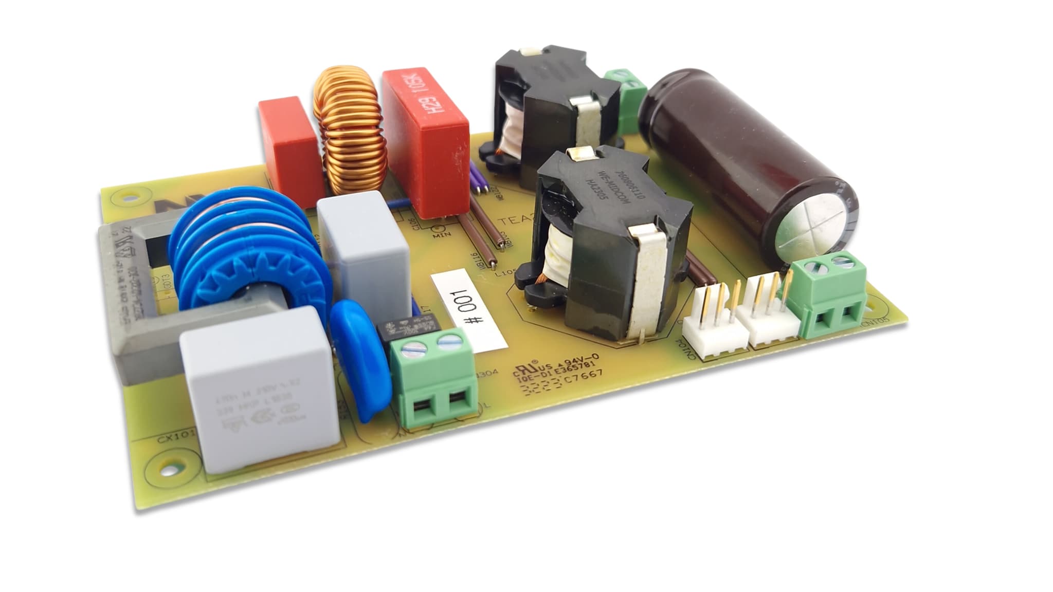
2.1 Board Description
The TEA2376DB1602v2 demo board can operate on a mains input voltage between 90 V (RMS) and 264 V (RMS), universal mains voltage.
The TEA2376DB1602v2 demo board incorporates two subcircuits:
- Active bridge rectifier
- Interleaved PFC converter
The purpose of the demo board is to demonstrate and evaluate the operation of the TEA2376DT and TEA2209T in a single output power supply, including the modes of operation in a typical design. The performance supports common standards, including current low-load and standby requirements. It can be used as a starting point for developing power supplies using the TEA2376 and TEA2209 controller ICs.
To show the benefits of an interleaved PFC with an active bridge rectifier, the TEA2376DB1602V2 board design was made on a single-sided copper PCB with standard MOSFET types and without heat sinks.
| Symbol | Description | Conditions | Values | Unit |
|---|---|---|---|---|
| Vi | input voltage | AC | 90 to 264 | V (RMS) |
| Fi | input frequency | - | 47 to 63 | Hz |
| Pi(no load)_mains | no-load input power | at 230 V/50 Hz | < 35 | mW |
| Pi(no load)_VCC | no-load input power | at VCC = 16 V (DC) | < 15 | mW |
| Vo | output voltage | normal mode | 395 | V |
| Vo(min, max) | output voltage variations | load-step response | < 10 | % |
| lo | output current | continuos | 0 to 0.76 | A |
| lo | output current | peak at nominal Vo | > 1 | A |
| tstart | start time | 115 V/60 Hz, lo = 0.76 A | 100 | ms |
| PF | power factor | lo = 0.76 A | 0.99 | - |
| η | efficiency | 115 V/60 Hz lo = 0.76 A | > 96 | % |
| η | efficiency | 230 V/50 Hz lo = 0.76 A | > 98 | % |
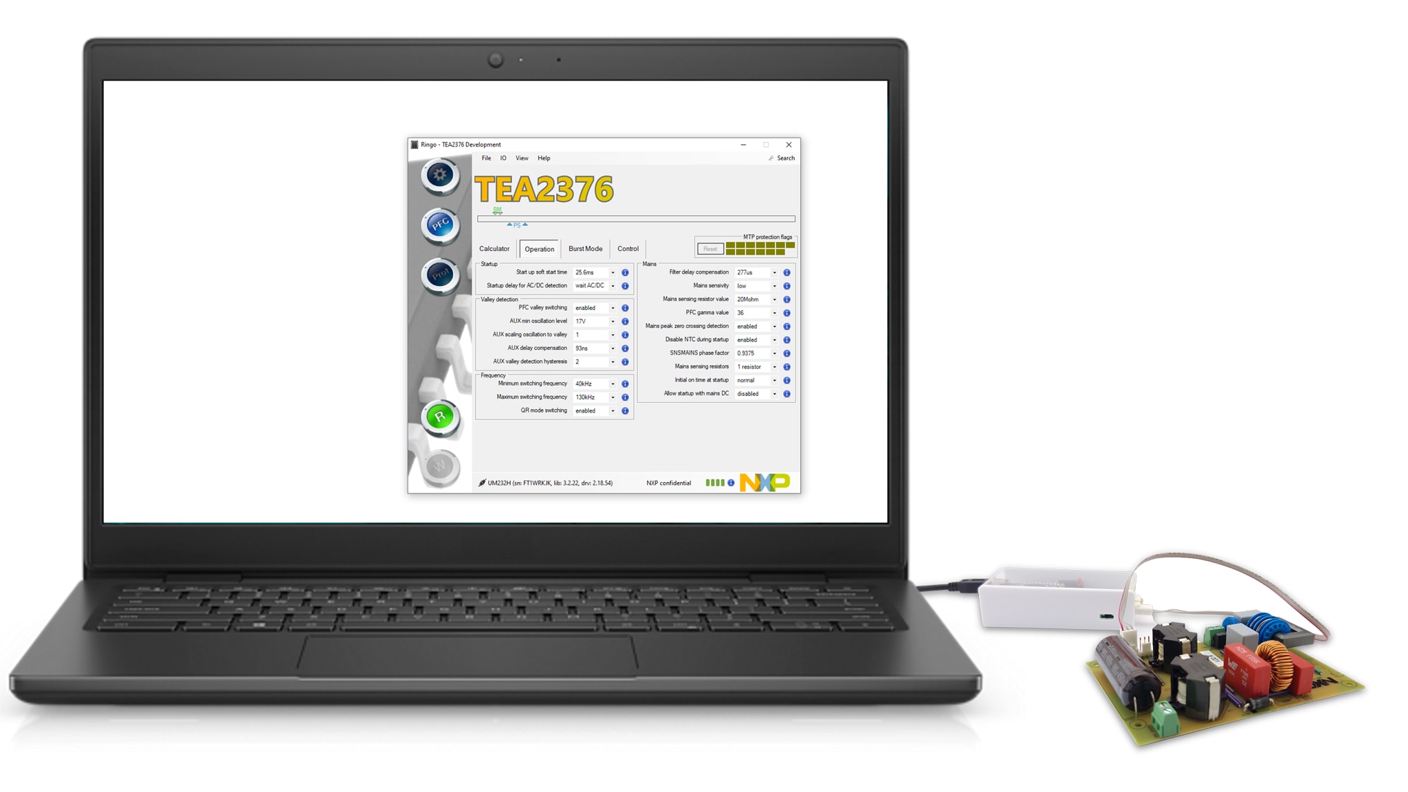
2.2 TEA2376 Ringo Software and USB-I²C Interface
On the TEA2376DB1602v2 board, the TEA2376DT (SO14) version is used. This version includes two dedicated pins for I²C communication that supports access to parameter modifications, which is useful for product development. During the power supply operation, settings can be modified and status information of the operation can be monitored.
During power supply development, the communication with the IC can be done using the Ringo software on a Windows OS PC with a USB-I²C interface (TEA2016DB1514 available as part of the RDK01DB1563 kit). The TEA2376 Ringo software with GUI provides the correct protocol and offers several options and tools to work with the IC settings and the readout status information.
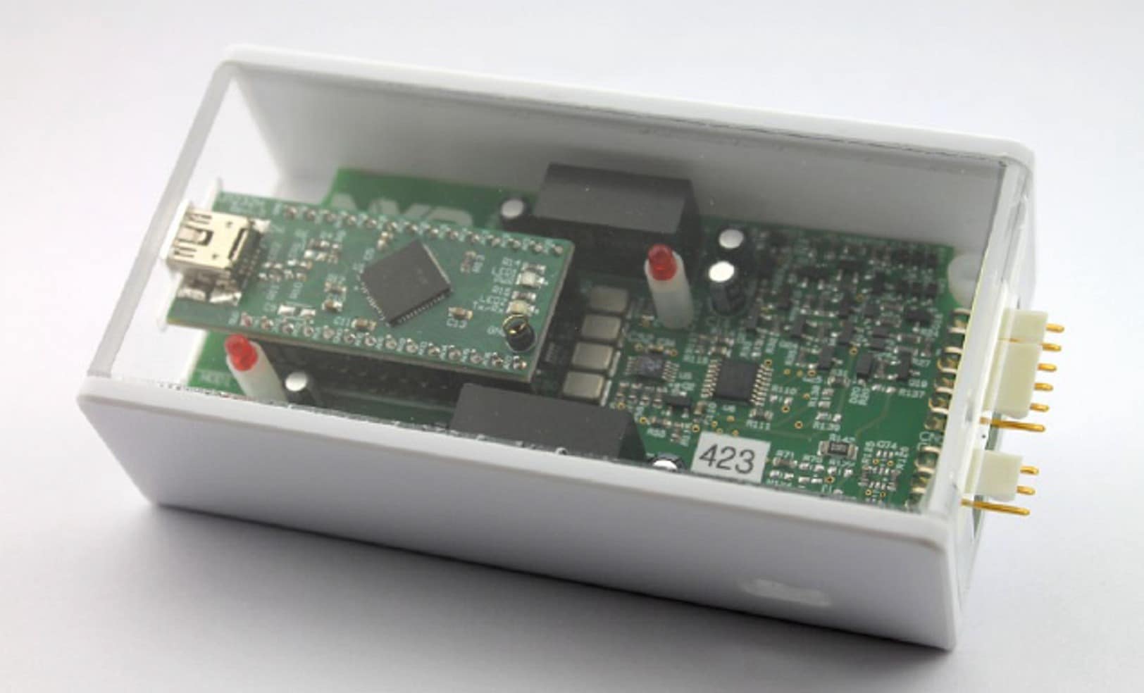
2.3 Interface Board
The TEA2016DB1514 interface board is a development tool that enables setting TEA2376 controller parameters from a computer. The available Ringo TEA2376 development software provides a graphical user interface (GUI) that can be installed on a computer.
The interface and software are intended for engineering work in a lab environment as part of power supply development. It is not suitable for consumer or industrial use.
3. Get Software
3.1 Install Software
Download the zip file with Ringo TEA2376 software to a folder on your computer and unzip the file.
For the Ringo software to work, the FT232H driver for the USB-I²C programming interface needs to be installed. This installation happens automatically when you connect the interface for the first time via USB. If the driver is not installed automatically, you can use the included drivers to do this manually.
Important: When the FT232H driver is not installed, the Ringo software does not work.
The Ringo program needs no installation. It can be started by double-clicking on Ringo.exe. Keep the other files and folders in the same directory because Ringo makes use of it.
4. Configure Hardware
4.1 Power Supply Setup
The TEA2376DB1602 demo board contains a TEA2376DT IC sample that can communicate via I²C during operation. It is connected to the interface with a 3-pin connection.
The I²C-USB interface with cables (RDK01DB1563 kit) can be used for several recent NXP power conversion controller ICs that have settings in MTP.
Design Resources
Support
Ringo Software
Q: Ringo.exe does not start.
- A1: The USB-I²C interface driver (FT232) needs to be installed on the computer to enable Ringo software to work
- A2: Make sure you are using a compatible version: 32bit or 64bit
- A3: Ringo is made for Windows operating systems. On other operating systems you can run it via a windows emulator
Q: Can I work with Ringo without the interface connected?
- A1: Yes, when the USB-I²C interface driver (FT232) is already installed
- A2: To get started the USB-I²C interface driver (FT232) needs to be installed on the computer to enable Ringo software to work. For this the interface needs to be connected (one time) to install the driver
Q: When I connect the USB-I²C interface it does not work.
- A1: A driver is needed to make the FT323 module operational. The driver is often automatically installed (plug and play) but sometimes a manual install is required. Watch the video “installing USB driver manually” on the NXP website. Consult the FTDI website for the latest driver updates
- A2: When you installed the driver and still it does not work: completely (‘delete the driver software for this device’) remove the driver and visit the FTDI chip website for more information on the latest driver version
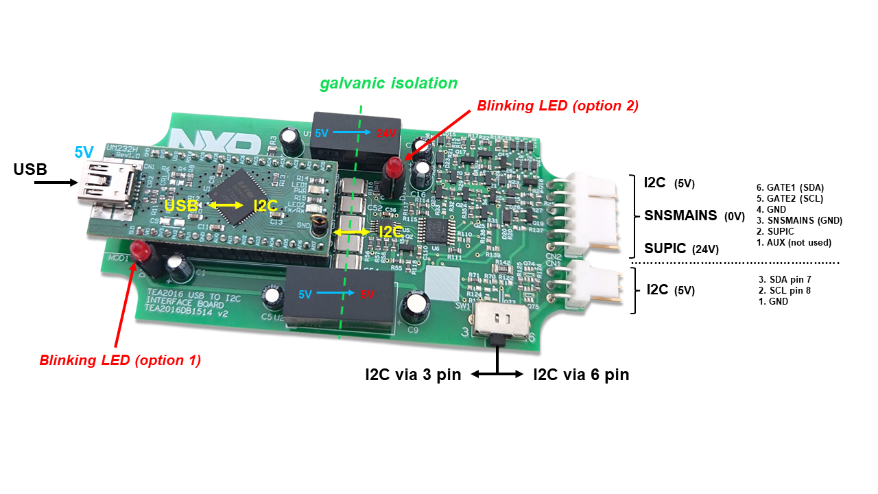
USB - I²C Interface
Q: There is no communication with the IC.
- A1: Check if the switch on the interface is in the correct position: 3pin or 6pin
- A2: Check if the correct cable is connected (or both when using the programming board)
- A3: Check if signal disturbance is blocking communication
Q: I want to make a modification or repair on the board. Is there a circuit diagram?
- A1: The circuit diagram is included in User Manual UM11235. This document is also available in the help tab of the Ringo software
Q: What is the function of the LEDs on the board?
- A1: The Ringo software can use them for indicating that the I²C connection is OK. The indication differs between Ringo versions. In general, slow blinking indicates no communication with the IC. And fast blinking indicates correct communication with the IC
Q: Do I need to buy the RDK01DB1563 kit, or can I also build an interface myself?
- A1: The RDK01DB1563 provides an easy connection with galvanic isolation and can be used for other NXP products as well. The Ringo software working is based on drivers for the UM232H module. It is also possible to use a separate UM232H module from FTDI. And apply it in a comparable way as it is used on the TEA2016DB1514v2 board (circuit diagram included in UM11235)