Design Files
2 design files
-
Printed Circuit Boards and Schematics
A3I25D080N 2600 MHz PCB DXF file
-
Printed Circuit Boards and Schematics
A3I25D080N 2300 MHz PCB DXF file
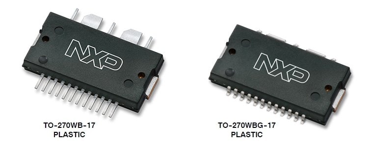
The A3I25D080N and A3I25D080GN integrated Doherty circuit is designed with on-chip matching that makes it usable from 2300 to 2690 MHz. This multi-stage structure is rated for 20 to 32 V operation and covers all typical cellular base station modulation formats.
Select a section:
Typical Doherty Single-Carrier W-CDMA Characterization Performance: VDD = 28 Vdc, IDQ(Carrier) = 175 mA, VGS(Peaking) = 1.85 Vdc, Pout = 8.5 W Avg., Input Signal PAR = 9.9 dB @ 0.01 % Probability on CCDF. (1)
Frequency | Gps (dB) |
PAE (%) |
ACPR (dBc) |
2496 MHz | 29.7 | 36.7 | -37.9 |
2590 MHz | 29.6 | 37.0 | -37.5 |
2690 MHz | 29.4 | 36.1 | -36.2 |
Typical Doherty Single-Carrier W-CDMA Performance: VDD = 28 Vdc, IDQ(Carrier) = 182 mA, VGS(Peaking) = 2.42 Vdc, Pout = 8.9 W Avg., Input Signal PAR = 9.9 dB @ 0.01 % Probability on CCDF. (1)
Frequency | Gps (dB) |
PAE (%) |
ACPR (dBc) |
2300 MHz | 30.3 | 36.1 | -36.2 |
2350 MHz | 30.2 | 35.5 | -38.7 |
2400 MHz | 30.2 | 35.2 | -39.5 |
1. All data measured in fixture with device soldered to heatsink.
Quick reference to our documentation types.
5 documents
Please wait while your secure files are loading.
Select a section:
2 design files
Please wait while your secure files are loading.