In
“IoT Sensing Software Development Kit,”
I introduced the new ISSDK component within the Kinetis SDK. I also mentioned
it included NXP Sensor Fusion for Kinetis MCUs Version 7.00. Today,
I’ll provide details.
NXP, and Freescale before it, have been providing an open source library for
development of sensor fusion applications for a couple of years now.
Version 4.22 started that trend. Version 5.00 followed a year later with
significant enhancements. Version 6.00 was never published. It added support
for precision accelerometer trim and storing of trim parameters into NVM. But
about that time, we learned that the CodeWarrior and Processor Expert tools
were being phased out for Kinetis MCUs. It was time to retool. That’s
where Version 7.00 comes into play. It is based on the V6.00 baseline,
but with a LOT of changes:
- The CodeWarrior software development tool support is retired
- Processor Expert software support is retired
- MQX RTOS support is retired
- FreeRTOS support has been added
-
Support for bare metal projects has been added. This also dramatically
reduces the amount of flash memory you need to store the application.
-
Because it is now part of the KEX ecosystem, you now get support for:
-
Kinetis Design Studio IDE v3.2
- IAR Embedded Workbench for Arm version 7.50.1
- MDK-ARM Microcontroller Development Kit (Keil)® 5.17
-
Makefiles support with GCC revision 4.9-2015-q3-update from Arm Embedded
- Atollic® TrueSTUDIO® 5.4.0
- Precision trim for accelerometers
-
Storage of all sensor trim values to non-volatile flash
memory (via the updated Sensor Fusion Toolbox for Windows)
-
Ability to power down selected sensors (specifically the gyro) during
periods of inactivity
-
Top-level functions have been re-partitioned to make it obscenely easy to
integrate sensor fusion capabilities into your code
-
Hardware facing functions have been streamlined for easy portability to
non-Kinetis platforms.
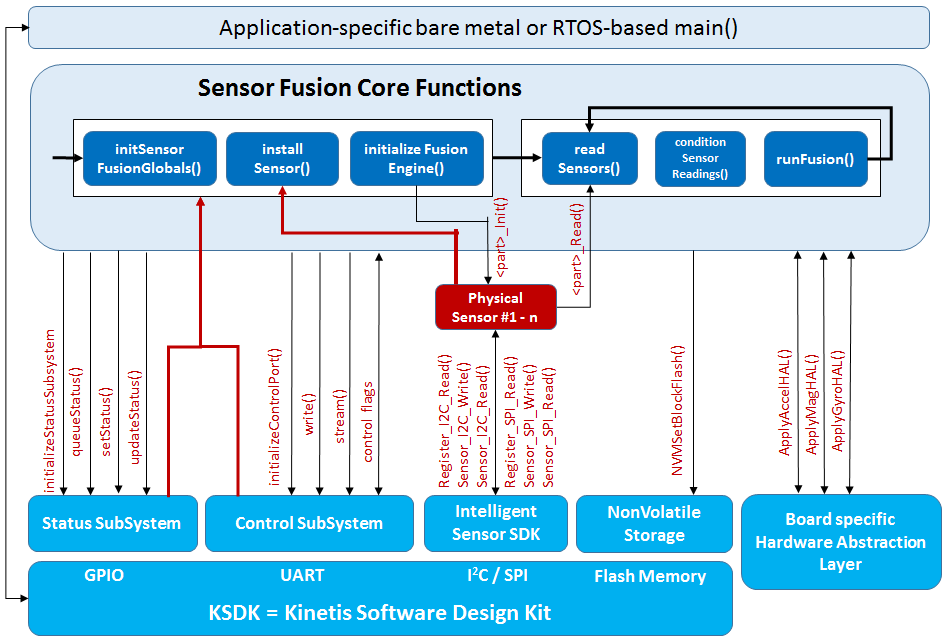
The block diagram below shows how the sensor fusion library fits into your
application. The number of top level functions you need to remember is
extremely modest. Sensor drivers are already provided for NXP sensors,
but it’s also easy to write your own if you want to enable some other
device.

In this solution, we will use the
FXOS8700 6-axis magnetometer and accelerometer,
FXAS21002 3-axis gyroscope and the
MPL3115 barometric pressure sensors. Let’s take a look at a bare metal main(). The
first code block pulls in headers specific to your hardware:
// KSDK  and ISSDK Headers
#include "fsl_debug_console.h"  // KSDK header file for the debug interface
#include "board.h"              // KSDK header file to define board configuration
#include "pin_mux.h"            // KSDK header file for pin mux initialization functions
#include "clock_config.h"       // KSDK header file for clock configuration
#include "fsl_port.h"           // KSDK header file for Port I/O control
#include "fsl_i2c.h"            // KSDK header file for I2C interfaces
#include "fsl_pit.h"            // KSDK header file for Periodic Interval Timer
#include "Driver_I2C.h"         // CMSIS I2C Driver
#include "Driver_I2C_SDK2.h"    // ISSDK CMSIS I2C Driver
#include "fxas21002.h"          // Gyroscope register and bit-field definitions
#include "mpl3115.h"            // Pressure sensor register and bit-field definitions
#include "fxos8700.h"           // 6-axis accel/mag register and bit-field definitions
#include "fsl_smc.h"
Next we include a number of sensor fusion headers:
#include "sensor_fusion.h"   // Top-level magCal and sensor fusion interfaces
#include "control.h"         // Command/Streaming interface - application-specific
#include "status.h"          // Status indicator interface - application-specific
#include "drivers.h"         // NXP sensor drivers OR customer-supplied drivers
#include "driver_pit.h"      // PIT is used to control main() timing loop
You will need to define a number of global data structures:
SensorFusionGlobals sfg;             ///< This is the primary sensor fusion data structure
ControlSubsystem controlSubsystem;   ///< Used for serial communications
StatusSubsystem statusSubsystem;     ///< Provides visual (usually LED) status indicator
PhysicalSensor sensors[3];           ///< This implementation uses up to 3 sensors
Now let’s take a look at main(). Start by doing some general hardware
configuration:
int main(void) // This is a bare-metal implementation of the NXP sensor fusion demo build.
{
    uint16_t i=0;                    // general counter variable
    BOARD_InitPins();                // defined in pin_mux.c, initializes pkg pins
    BOARD_BootClockRUN();            // defined in clock_config.c, initializes clocks
    BOARD_InitDebugConsole();        // defined in board.c, initializes the OpenSDA port
Next, initialize the I2C-bus used for sensor communications:
    ARM_DRIVER_I2C* I2Cdrv = &I2C_S_DRIVER_BLOCKING;            // Defined by ISSDK
    I2Cdrv->Initialize(NULL);                                   // Initialize the I2C KSDK driver
    I2Cdrv->Control(ARM_I2C_BUS_SPEED, ARM_I2C_BUS_SPEED_FAST); // Configure the I2C-bus speed
Now initialize various subsystems associated with sensor fusion:
    initializeControlPort(&controlSubsystem);     // configure pins and ports for the control sub-system
    initializeStatusSubsystem(&statusSubsystem);  // configure pins and ports for the status sub-system
    // Initialize sensor fusion structures
    initSensorFusionGlobals(&sfg, &statusSubsystem, &controlSubsystem);
Sensors are installed at runtime:
    sfg.installSensor(&sfg, &sensors[0], FXOS8700_I2C_ADDR,  1, (void*) I2Cdrv, FXOS8700_Init,  FXOS8700_Read);
    sfg.installSensor(&sfg, &sensors[1], FXAS21002_I2C_ADDR, 1, (void*) I2Cdrv, FXAS21002_Init, FXAS21002_Read);
    sfg.installSensor(&sfg, &sensors[2], MPL3115_I2C_ADDR,   1, (void*) I2Cdrv, MPL3115_Init,   MPL3115_Read);
Start up the fusion engine, hardware timer and initial status:
    sfg.initializeFusionEngine(&sfg);    // This will initialize sensors and magnetic calibration
    pit_init(1000000/FUSION_HZ);         // pitIsrFlag will be set true at FUSION_HZ periodic intervals
    sfg.setStatus(&sfg, NORMAL);         // If we got this far, let's set status state to NORMAL
Now we have our main loop, which is timed via a periodic interval timer:
    while (true)
    {
        if (true == pitIsrFlag) {               // Check whether occur interupt and toggle LED
            sfg.readSensors(&sfg, 1);           // Reads sensors, applies HAL and does averaging
            sfg.conditionSensorReadings(&sfg);  // MagCal is run as part of this
            sfg.runFusion(&sfg);                // Run the actual fusion algorithms
            sfg.loopcounter++;                  // Used to "serialize" mag cal operations
            i=i+1;
            if (i>=4) {                         // Some status codes include a "blink" feature.  This loop
                    i=0;                        // should cycle at least 4X for that to operate correctly.
                    sfg.updateStatus(&sfg);     // This is where pending status updates are made visible
            }
            sfg.queueStatus(&sfg, NORMAL);      // assume NORMAL status for next pass through the loop

            // Send stream data to the Sensor Fusion Toolbox
            sfg.pControlSubsystem->stream(&sfg, sUARTOutputBuffer);
            pitIsrFlag = false;                 // Reset the flag for the next cycle
        }
    }
}
Even though we’ve used standard C, we’ve used an objected
oriented coding style for the top-level interface. Functions that
operate on a structure are actually installed as part of that structure, just
as in C++. Status and control subsystems are installed at runtime. This allows you to install your own versions rather than use the
NXP defaults. Sensors to be used by the application are also explicitly
installed. Then we simply start the fusion subsystem and a system timer
and drop into a main loop.
I think you will agree that this release makes it easier to see and comprehend
the overall application structure than it was with previous libraries. To find
more information, go to
NXP® Sensor Fusion
and
MCUXpresso SDK Builder
to download this release and
nxp.com/FRDM to order development boards.
Our next posting in the series will look at sensor drivers and a FreeRTOS
implementation of the same application shown in bare metal form above.
Michael Stanley “works” on fun sensors and systems
topics.


