Getting Started with JN5189
Contents of this document
-
Plug It In
-
Get Software
-
Build, Run
-
Learn
Sign in to save your progress. Don't have an account? Create one.
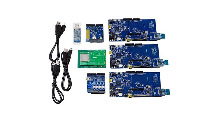
Purchase your JN5189 Development Kit | Wireless MCU
1. Plug It In
Let's take your JN5189 board for a test drive! You have the choice of watching the sequence in a short video or following the detailed actions list below.
1.1 Attach the USB Cable
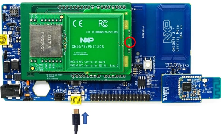
The green light on the PN7150 NFC control shield will blink once powered.
1.2 Collaterals Package Download
The FTDI driver allows the board to communicate with your PC.
The ZGWUI.exe file is used to setup the ZigBee network. It is available from the
JN-AN-1247-ZigBee-3-0-ControlBridge package folder AN1247\Tools\TestGUI\Source\bin\Debug.
1.3 Start your Network
On your PC, open the Zigbee Gateway User Interface (ZGWUI) by double clicking on the executable file ZGWUI.exe.
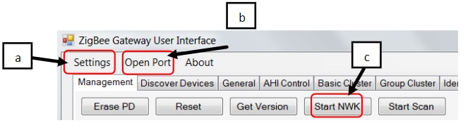
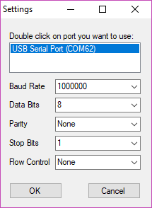
- Click on the ‘Settings menu: select the COM port connected to the control bridge and click on ‘OK’
- Click on ’Open Port’ menu (button state changes to ‘Close port’)
- Click on ‘Start NWK’, you can see at the bottom left of the ZGWUI window the raw data and bottom right the received message log
1.4 Commission the Network via NFC
- Connect the light node to a PC USB port
- Tap the NFC antenna of the light node on the NFC antenna of the control bridge:
- Repeat step 1 and 2 with the generic switch node
- The 2 nodes are present on ‘Discover Devices’ tab of the ZGWUI:
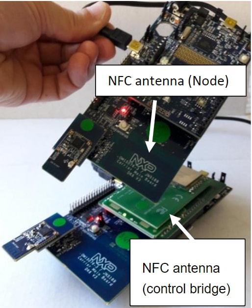
The green LED on the NFC reader shield blinks more quickly during commissioning and then returns back to its initial state. The node is then commissioned
Click on ‘Discover devices’ button, there are 2 short addresses listed standing for the 2 nodes:
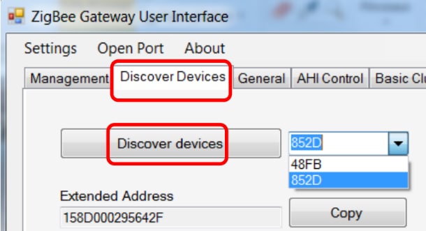
In case none or only one short address is present but not 2, redo the commissioning nodes from step 2.
1.5 Controlling the Light from the Generic Switch Node
-
Bind the generic switch node to the light node as follows:
- Light node: Press and release the USER INTERFACE button. The 3 white LEDs will start to f lash
-
Generic switch node:
- Press and release SW1
-
Hold down the USER INTERFACE button:
Once LED D1 starts flashing on the generic switch node, press and release the SW2 button
Release the USER INTERFACE button only when the light node LEDs stay ON
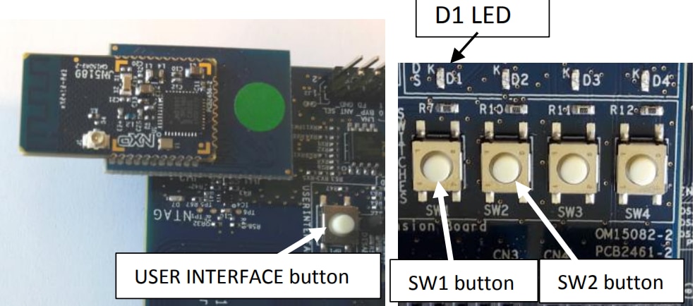
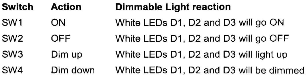
- Experiment with the buttons SW1 to SW4 to control the white LEDs on the Light node, as follows:
2. Get Software
2.1 Download MCUXpresso SDK with Connectivity Software
MCUXpresso SDK for the JN5189 integrates the MCUXpresso Software Development Kit with all the wireless connectivity stacks required to develop your solution with ZigBee.
Click below to download a pre-configured SDK release for the JN5189 that includes the wireless connectivity ZigBee stack for the JN5189.

Extract the contents of the download SDK zip and locate the flash programmer installer
SDK_X.X.X_JN5189DK6\tools\JN-SW-4401-DK6-Flash-Programmer. Add the installation location to
your system path.
2.2 Install Your Toolchain
NXP offers a complimentary toolchain called MCUXpresso IDE.

2.3 Install Python 3.8
The JN5189 bootloader requires an image signature to verify the validity of a binary image. The image signing tool requires a Python install to exist on the PC. Download and the latest install Python 3.8 and add it to your system path. Then in a terminal window enter pip install pycryptodome to install the library.
3. Build, Run
The JN5189 Wireless Connectivity Stack comes with a list of demo applications and driver examples ready to be compiled and run.
3.1 Install the SDK
To install the SDK, open MCUXpresso and drag and drop the SDK zip file into the installed SDKs window. Confirm the installation to copy the SDK into the MCUXpresso IDE framework.
3.2 Import SDK Examples
From the quickstart panel, select “Import SDK examples”, select JN5189DK6, click next and choose wireless example of your choice. (Refer to the wireless example’s documentation to find out more information). Then click finish to import the project.
3.3 Build your Project
Build your imported project by selecting “Build” in the quickstart panel. Once complete, a binary file (.bin) will be generated inside the project folder under the folder called “Debug” (the name of the selected build configuration).
3.4 Flash your Device
Open a terminal window in the location of your binary file
Your_MCUxpresso_Workspace\Project_Name\Debug. In your terminal window enter:
DK6Programmer -l
To list your connected COM ports. Identify the COM port of your device, then enter:
DK6Programmer -s <COMPORT> -p <BINARY_FILENAME.bin></BINARY_FILENAME.bin>
This will program the board with your newly built binary. Congratualtions!
3.5 Running a Demo Using IAR
The following steps will guide you through compiling, flashing, and running a simple Heart Rate Sensor ZigBee application using the JN5189 board.
Build a ZigBee Application
-
Navigate to the Heart Rate Sensor workspace located at
''\boards\JN5189cdk\wireless_examples\bluetooth\heart_rate_sensor\freertos\iar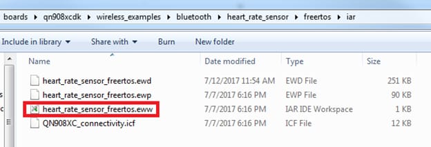
-
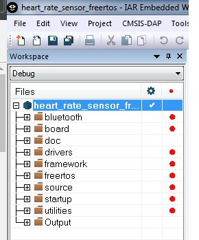
After the workspace is open, select the project
-
Click the Make button to build the project
Download and Run the Application Demo
-
Connect the first JN5189 board to your PC if it is not already. Use the
J2USB connector on the JN5189 -
Open the terminal application on the PC (such as PuTTY or TeraTerm) and connect to the debug COM port you determined earlier. Configure the terminal with these settings:

-
Click the "Download and Debug" button to download the application to the target
-
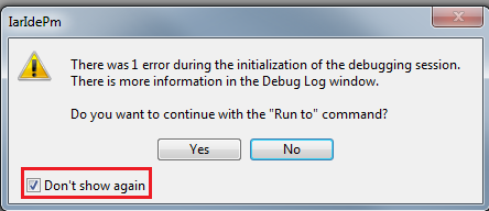
The firmware will be downloaded to the board and then you may see the following message. Check the “Don’t show again” checkbox and then click on the Yes button
-
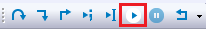
The debugger will then be started. Click on the “Go” button to begin running the demo
Run the Heart Rate Sensor Demo
-
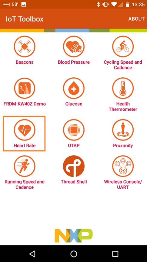
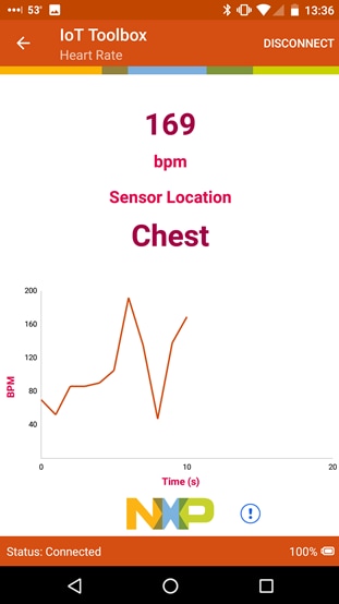
Open the NXP IoT Toolbox application on your mobile device and click on the Heart Rate icon
-
On the JN5189 board, press Buton1 to begin ZigBee advertising
-
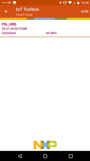
In the smartphone app, you should now see the FSL_HRS name. Click on it
-
The board will then connect to the phone, and you’ll see a graph of the random BPM reading
3.6 Use Keil MDK
Install CMSIS Device Pack
After the MDK tools are installed, Cortex® Microcontroller Software Interface Standard (CMSIS) device packs must be installed to fully support the device from a debug perspective. These packs include things such as memory map information, register definitions and flash programming algorithms. Follow these steps to install the appropriate CMSIS pack.
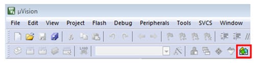
- Open the MDK IDE, which is called μVision. In the IDE, select the “Pack Installer” icon
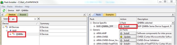
- In the Pack Installer window, search for “JN” to bring up the JN5189 family. Click on the JN5189 name, and then in the right hand side you’ll see the NXP::JN5189_DFP pack. Click on the “Install” button next to the pack. This process requires an internet connection to successfully complete
- After the installation finishes, close the Pack Installer window and return to the µVision IDE
- Build an Example Application
The following steps will guide you through opening the heart_rate_sensor ZigBee demo.
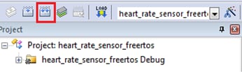
- Inside the MDK, go to Project→Open Project
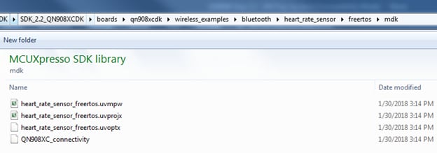
- Navigate to the Heart Rate Sensor workspace located at
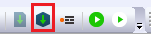
\boards\JN5189cdk\wireless_examples\bluetooth\heart_rate_sensor\freertos\keiland open the heart_rate_sensor_freertos.uvprojx project - To build the demo project, select the "Rebuild" button, highlighted in red
- The build will complete without errors
Run an Example Application
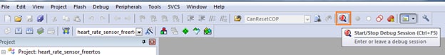
-
Connect the first JN5189 board to your PC if it is not already. Use the
J2USB connector on the JN5189 - Click on the Start/Stop Debug Session button to download the code to the board and start debugging it
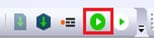
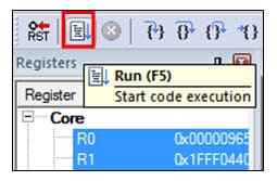
- Run the code by clicking the "Run" button to start the application
Run the Heart Rate Sensor Demo
- Open the NXP IoT Toolbox application on your mobile device and click on the Heart Rate icon
- On the JN5189 board, press Buton1 to begin ZigBee advertising.
- In the smartphone app, you should now see the FSL_HRS name. Click on it
- The board will then connect to the phone, and you’ll see a graph of the random BPM reading


3.7 Running a Demo Using MCUXpresso IDE
The following steps will guide you through opening the hybrid example. This project will be loaded to one board, while another project will be loaded on the 2nd board.
-
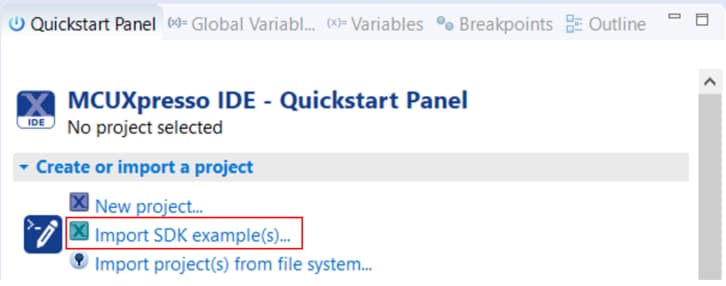
Find the Quickstart Panel in the lower left hand corner
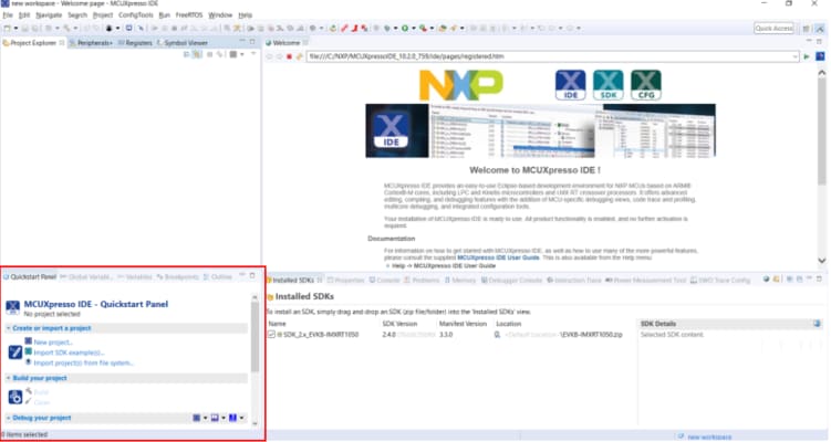
-
Then click on Import SDK examples(s)…
-
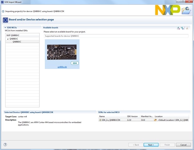
Click on the JN5189 board to select that you want to import an example that can run on that board, and then click on Next
-
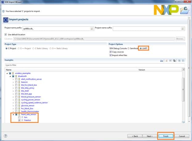
Now we need to select the project to import. Use the arrow button to expand the wireless_examples category, and then under the bluetooth category expand the heart_rate_sensor project and select the freertos version of project
This particular project doesn’t make use of the UART, but for projects that do, select the “UART” option for the SDK Debug Console. Then, click on Finish
-
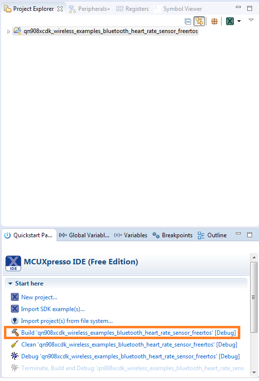
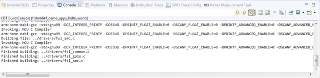
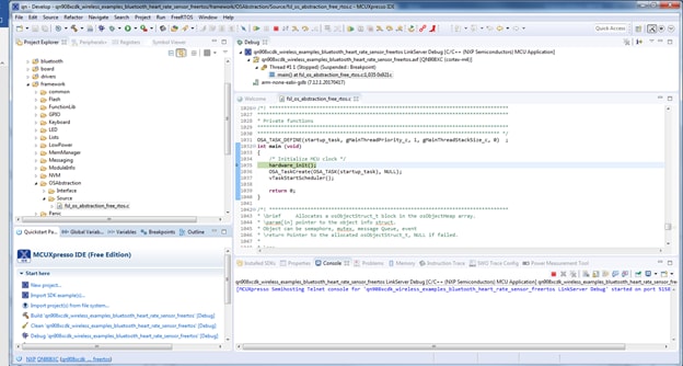
Now build the project by clicking on the JN5189cdk_wireless_examples_bluetooth_heart_rate_sensor_freertos project name and then in the Quickstart Panel click on Build
-
You can see the status of the build in the Console tab. If you get a compile error, make sure you had imported two projects at the same
Download and Run the Application Demo
-
Connect the first JN5189 board to your PC if it is not already. Use
the
J2USB connector on the JN5189 -
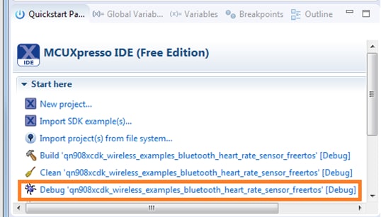
In the Quickstart Panel click on
Debug
‘JN5189cdk_wireless_examples_bluetooth_heart_rate_sensor_freertos’
[Debug]
-
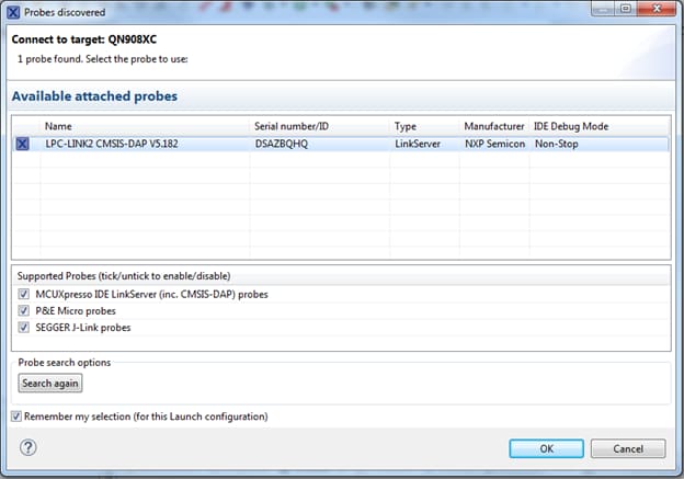
MCUXpresso IDE will probe for connected boards and should find the LPC-LINK2 CMSIS-DAP debug probe that is part of the integrated debug circuit on the JN5189. Click on OK to continue
-
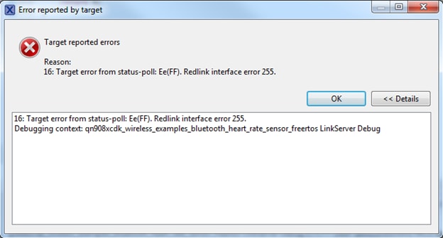
You may get the following error. Hit “OK” to dismiss it
-
The firmware will be downloaded to the board and the debugger started
Run the Heart Rate Sensor Demo
-
Open the NXP IoT Toolbox application on your mobile device and click on the Heart Rate icon
-
On the JN5189 board, press Buton1 to begin ZigBee advertising
-
In the smartphone app, you should now see the FSL_HRS name. Click on it
-
The board will then connect to the phone, and you’ll see a graph of the random BPM reading
4. Learn
4.1 Sensors
Explore the world with a full assortment of NXP sensor solutions. From accelerometers, pressure sensors, touch sensors, and many more, NXP has a sensor solution for your project. Find out more at Sensors.
4.2 NFC
Near Field Communication is a simple, intuitive technology that lets you interact securely with the world around you with a simple touch. Learn more about NXP’s NFC solutions at NFC - Near Field Communication.
Support
Troubleshooting
Did your board come in a box that looks like this?
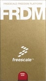
No problem! Your board simply came in the old packaging and has a different out-of-box demo loaded into the flash memory.
You should be seeing the RGB LED toggling between each of the three colors; red, blue and green. It's OK to move onto the next step when you're ready.
Still not working?
Try proceeding to the next steps to get other example applications running on your board. If you still have problems, try contacting us through the NXP Community.
Forums
Connect with other engineers and get expert advice on designing with JN MCUs and Wireless Connectivity software. Join the community discussion in the Wireless Connectivity Community
On this page
- 1.1
Attach the USB Cable
- 1.2
Collaterals Package Download
- 1.3
Start your Network
- 1.4
Commission the Network via NFC
- 1.5
Controlling the Light from the Generic Switch Node
- 2.1
Download MCUXpresso SDK with Connectivity Software
- 2.2
Install Your Toolchain
- 2.3
Install Python 3.8