Getting Started with the Bidirectional DC-DC Reference Solution
Contents of this document
-
Out of the Box
-
Get the Hardware
-
Configure Hardware
-
Install Software Tools
Sign in to save your progress. Don't have an account? Create one.

Purchase your 800W Bidirectional DC-DC Conversion Solution Based on Programable Digital Signal Controller
1. Out of the Box
NXP reference design solutions provide you with an easy-to-start platform, which allowing you to shorten development cycles, and keep up with industry trends. This page guides you through the process of setting up and using the bidirectional DC-DC reference platform.
1.1 Hardware Requirements
-
The hardware required includes:
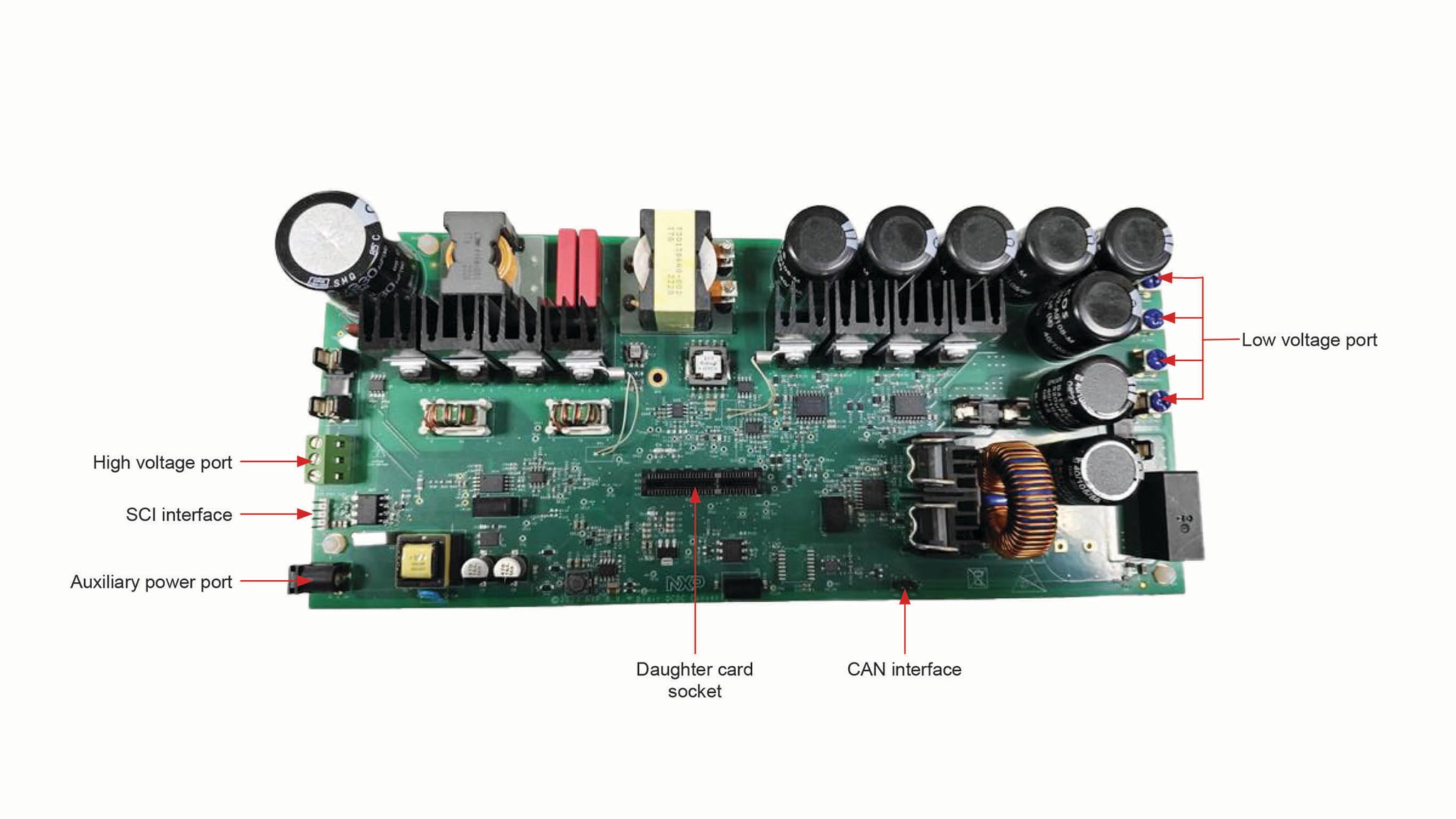
- Bidirectional DC-DC power board (The Gerber and BOM are provided by NXP, but not the board)
- MCU control expansion card (HVP-56F83783)
A detailed user manual and an application note are available on the bidirectional DC-DC reference design webpage to explain the comprehensive operation of the software, platform assembly, and startup process.
1.2 Other Hardware
-
In addition, the following hardware is necessary or beneficial when working with this platform.
- Power supply: DC source up to 400 V/3 A for battery charge mode, DC source up to 60 V/30 A for battery discharge mode.
- Load: DC electronic load up to 400 V/3 A for battery discharge mode, DC electronic load up to 60 V/30 A for battery charge mode.
- Cable assembly, double row wire cable.
- A PC to run the provided graphical user interface (FreeMASTER) and USB-Mini-B connector for FreeMASTER connection.
- A Universal Multilink or DSC Multilink to program the controller.
1.3 Software
In addition to the kit contents, FreeMASTER is necessary for working mode selection and start and stop control.
2. Get the Hardware
The bidirectional DC-DC reference design is developed for evaluation and development purposes. It is composed of a hardware and a software package. The hardware includes two PCBs as described in Section 1.1, the HVP-56F83783 expansion card is plugged into the expansion card socket on the power board. The board schematic and layout are available on the bidirectional DC-DC reference design webpage.
2.2 HVP-56F83783
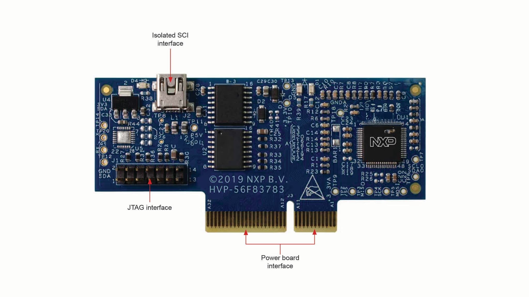
The NXP High-Voltage-Development platform enables evaluation and development of high-voltage motor control and power conversion algorithms. It is ideal for rapid prototyping of high-voltage microcontroller-based applications. For more information, visit the HVP-MC3PH website.
3. Configure Hardware
The bidirectional DC-DC reference design supports bidirectional power conversion. The hardware configurations are different for different operating modes.
3.1 Hardware Connections
BCM Mode
- Plug HVP-56F83783 into the expansion card socket on the power board.
- Connect the DC source on the high-voltage port to supply DC voltage.
- Connect the load on the low voltage port.

BDM Mode
- Plug HVP-56F83783 into the expansion card socket on the power board.
- Connect the DC source on the low voltage port to supply DC voltage.
- Connect the load on the high-voltage port.

3.2 Control and Monitor the System Using FreeMASTER
- Connect isolated SCI interface J2 on HVP-56F83783 to the PC through a USB-Mini-B cable.
- Open the FreeMASTER project (Bidir_DCDC_MC56F83783.pmpx) with latest FreeMASTER.
- Configure the USB connection on FreeMASTER.
- Click Go or click Connect in the FreeMASTER menu to start the communication.
4. Install Software Tools
4.1 CodeWarrior IDE
The SDK is complimentary and includes full source code under a permissive open source license for all hardware abstraction and peripheral driver software.
Install revision: SDK_2_13_1_MC56F83783
- Use the online SDK Builder to create the SDK package. The SDK builder is available at: Digital Signal Controllers Developer Resources | MCUXpresso SDK.
4.2 Software Development Kit (SDK)
The SDK is complimentary and includes full source code under a permissive open source license for all hardware abstraction and peripheral driver software.
Install revision: SDK_2_13_1_MC56F83783
- Use the online SDK Builder to create the SDK package. The SDK builder is available at: Digital Signal Controllers Developer Resources | MCUXpresso SDK .
4.3 MCUXpresso Config Tools
The MCUXpresso Config Tool is an integrated suite of configuration tools that guides users in creating MCUXpresso SDK projects, and provides pin, clock peripheral tools to generate initialization C code for custom board support. Install revision: MCUXpresso Config Tools v15
- The config tool installer is available for download at: Digital Signal Controllers Developer Resources | MCUXpresso Config Tools | Downloads.
- Installation instructions and additional information are available at: Digital Signal Controllers Developer Resources | MCUXpresso Config Tools | Documentation.
4.4 FreeMASTER
FreeMASTER is a user-friendly real-time debug monitor and data visualization tool that enables runtime configuration and tuning of embedded software applications. Install revision: FreeMASTER tool 3.2
- The FreeMASTER installer is available for download at: Digital Signal Controllers Developer Resources | FreeMASTER | Downloads.
To use the CP210x USB to UART bridge virtual COM port communication on HVP-MC56F83783, download, and install the CP210x drivers .