Getting Started with the EVBMA7318-SPI Evaluation Board
Contents of this document
-
Out of the Box
-
Get Hardware
-
Configure Hardware
Sign in to save your progress. Don't have an account? Create one.
Purchase your EVBMA7318-SPI
1. Out of the Box
The NXP analog product development boards provide an easy-to-use platform for evaluating NXP products. The boards support a range of analog, mixed-signal and power solutions. They incorporate monolithic integrated circuits (ICs) and system-in-package (SiP) devices that use proven high-volume technology. NXP products offer longer battery life, a smaller form factor, reduced component counts, lower cost and improved performance in powering state-of-the-art systems.
This page guides you through the process of setting up and using the EVBMA7318-SPI evaluation board.
1.1 Kit Contents and Packing List
The EVBMA7318-SPI kit contents include:
- EVBMA7318-SPI board
- Battery simulation cable x 1: power supply for battery cell controller (BCC) simulate each cell by series resistors
- Current measurement cable x 1 - connect to SHUNT and its calibration NTC
- Transform physical layer (TPL) daisy chain cable x 1: cable to communicate with other boards by TPL
- Serial peripheral interface (SPI) communication cable x 2: cable to communicate with UMFT4222EV/controller board by SPI
- Debug cable with UMFT4222EV board x 1
1.2 Additional Hardware
No additional hardware is required for device evaluation, however a power supply 24 voltage direct current (VDC) with current capability of 500 mA or a four-to-18-cell battery pack is recommended. In addition to the kit contents, the following (optional) hardware is beneficial when working with this kit:
- External SHUNT and current resource that can be connected to SHUNT
- Battery emulator board BATT-7318EMU (access link: BATT-7318EMU)
- Power supply 5 VDC with current capability 500 mA
1.3 Minimum System Requirements
This evaluation board requires a Windows PC. Verifying that your system meets the minimum specifications (Windows® 11/10/8/7, Windows XP, or Vista in 32-bit or 64-bit version ) will ensure reliable performance while using this evaluation board.
1.4 Software
Software must be installed before working with this evaluation board. Install the following programs:
- Graphical user interface (GUI): ScriptGUI V3.5+
- ScriptGUI plugin for BMA7318
All listed software is available on the evaluation board's information page at EVBMA7318-SPI or from NXP GUI page SWBMS-ScriptGUI-D.
2. Get Hardware
2.1 Board Features
The EVBMA7318-SPI evaluation board features are the following:
- Distributed battery management system (BMS) architecture
- One BMA7318 on one board
- Can measure voltage for up to 18 battery cells with high accuracy
- 10 temperature-sensing channels
- TPL isolation communication
- SPI communication to controller and SPI2TPL bridge to forward data
- Cell balancing current up to 300 mA
- Current measurement channel with precision or fast mode
- High electromagnetic compatibility (EMC) performance
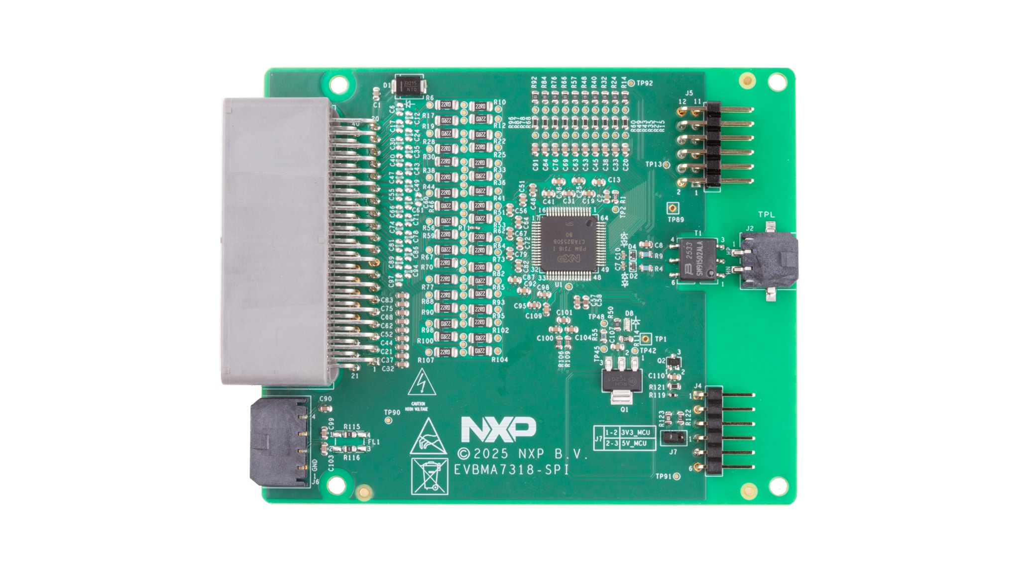
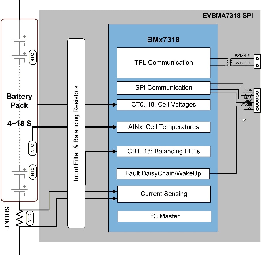
2.2 Board Description
This board includes one BMA7318 device. As shown in the diagram, the board communicates with a controller board or controller PC through SPI and communicates with other cell monitoring unit (CMU) boards through TPL with transformer isolation. Each board measures lithium-ion batteries with four to 18 cells. The board operates from a nine VDC to 90 VDC power source.
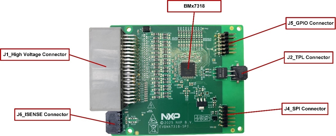
2.3 Board Components
Figure 2 identifies important components on the board and Table 1 provides additional details on these components.
| Number | Devices | Description |
|---|---|---|
| 1 | BMA7318FAIAE | 18-Channel Li-ion battery cell controller IC |
2.4 Connectors
| Pin | Name | Description |
|---|---|---|
| 1 | NC | No connect |
| 2 | NTC7 | Should connect to an external NTC resistor for temperature sensing |
| 3 | NTC6 | Should connect to an external NTC resistor for temperature sensing |
| 4 | NTC5 | Should connect to an external NTC resistor for temperature sensing |
| 5 | NTC4 | Should connect to an external NTC resistor for temperature sensing |
| 6 | NTC3 | Should connect to an external NTC resistor for temperature sensing |
| 7 | NTC2 | Should connect to an external NTC resistor for temperature sensing |
| 8 | NTC1 | Have connected to an internal NTC resistor for PCB temperature sensing |
| 9 | GND | Ground of BCC |
| 10 | C1P | Cell 1 voltage sensing point |
| 11 | C3P | Cell 3 voltage sensing point |
| 12 | C5P | Cell 5 voltage sensing point |
| 13 | C6Pb | Cell 6 voltage sensing point b |
| 14 | C8P | Cell 8 voltage sensing point |
| 15 | C10P | Cell 10 voltage sensing point |
| 16 | C12Pa | Cell 12 voltage sensing point a |
| 17 | C13P | Cell 13 voltage sensing point |
| 18 | C15P | Cell 15 voltage sensing point |
| 19 | C17P | Cell 17 voltage sensing point |
| 20 | PVWR | Power supply for BCC |
| 21 | NC | No connect |
| 22 | NTC8 | Should connect to an external NTC resistor for temperature sensing |
| 23 | NTC9 | Should connect to an external NTC resistor for temperature sensing |
| 24 | GND | Ground of NTC resistors |
| 25 | GND | Ground of NTC resistors |
| 26 | GND | Ground of NTC resistors |
| 27 | GND | Ground of NTC resistors |
| 28 | GND | Ground of NTC resistors |
| 29 | GND | Ground of NTC resistors |
| 30 | COM | Cell 0 voltage sensing point |
| 31 | C2P | Cell 2 voltage sensing point |
| 32 | C4P | Cell 4 voltage sensing point |
| 33 | C6Pa | Cell 6 voltage sensing point a |
| 34 | C7P | Cell 7 voltage sensing point |
| 35 | C9P | Cell 9 voltage sensing point |
| 36 | C11P | Cell 11 voltage sensing point |
| 37 | C12Pb | Cell 12 voltage sensing point b |
| 38 | C14P | Cell 14 voltage sensing point |
| 39 | C16P | Cell 16 voltage sensing point |
| 40 | C18P | Cell 18 voltage sensing point |
| Pin | Name | Description |
|---|---|---|
| 1 | H_INOUT+ | Positive of TPL_H twisted wire |
| 2 | H_INOUT- | Negative of TPL_H twisted wire |
| Pin | Name | Description |
|---|---|---|
| 1 | WAKEIN_CON | Wake-up input |
| 2 | CSN | SPI chip select input from controller |
| 3 | MOSI | SPI target data input from controller |
| 4 | MISO_CON | SPI target data output to controller |
| 5 | SCLK | SPI clock input from controller |
| 6 | GND | GND of SPI |
| Pin | Name | Description |
|---|---|---|
| 1 | GPIO0 | GPIO0 debug |
| 2 | GPIO9/ALARMOUT | GPIO9/ALARMOUT debug |
| 3 | GPIO1 | GPIO1 debug |
| 4 | GPIO8 | GPIO8/SPI status indication debug |
| 5 | GPIO2 | GPIO2 debug |
| 6 | GPIO7 | GPIO7/OCOUT debug |
| 7 | GPIO3 | GPIO3 debug |
| 8 | GPIO6 | GPIO6 debug |
| 9 | GPIO4 | GPIO4 debug |
| 10 | GPIO5 | GPIO5 debug |
| 11 | GND | GND of GPIO |
| 12 | GND | GND of GPIO |
| Pin | Name | Description |
|---|---|---|
| 1 | GND | GND of NTC |
| 2 | ISENSE- | Current sense input _ Negative |
| 3 | ISENSE+ | Current sense input _ Positive |
| 4 | NTC_SHUNT | Should connect to SHUNT NTC resistor for temperature sensing |
3. Configure the Hardware
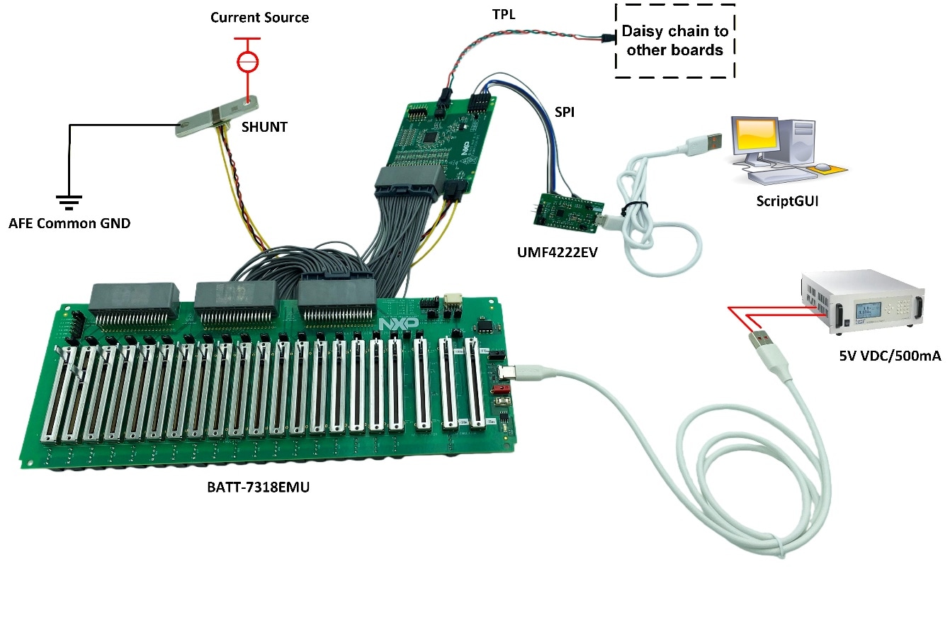
Figure 3 and Figure 4 present a typical hardware configuration that includes the development board, power supply and Windows PC workstation.
3.1 Setup Based on Battery Simulation Cable
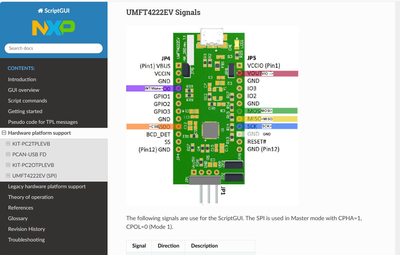
The setup uses ScriptGUI and requires the UMFT4222EV to connect the EVBMA7318-SPI to the controller PC. The EVBMA7318-SPI will be debugged through ScriptGUI.
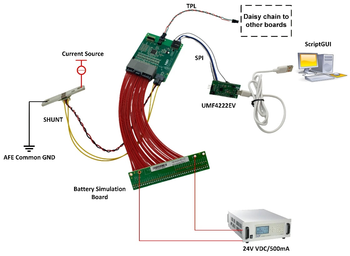
This setup is suitable for EVB based on the BMA7318FAIAE. For instructions on connecting the UMFT4222EV, refer to the ScriptGUI help document (see Figure 4).
Design Resources
Board Information
Additional References
- EVBMA7318-SPI - EVBMA7318-SPI—Detailed information on this board, including documentation, downloads, and software and tools
- BMA7318-BMI7318-BMA7518 - BMx7318—Detailed information on BMx7318, 18-Channel Li-ion battery cell controller IC.