Getting Started with the NAFE33352 Evaluation Board
Contents of this document
-
Out of the Box
-
Get Hardware
-
Configure Hardware
Sign in to save your progress. Don't have an account? Create one.
Purchase your NAFE33352-EVB
1. Out of the Box
The NXP analog product development boards provide an easy-to-use platform for evaluating NXP products. The boards support a range of analog, mixed-signal and power solutions. They incorporate monolithic integrated circuits and system-in-package devices that use proven high-volume technology. NXP products offer longer battery life, a smaller form factor, reduced component counts, lower cost, and improved performance in powering state-of-the-art systems.
This page will guide you through the process of setting up and using the NAFE33352-EVB board.
1.1 Kit Contents and Packing List
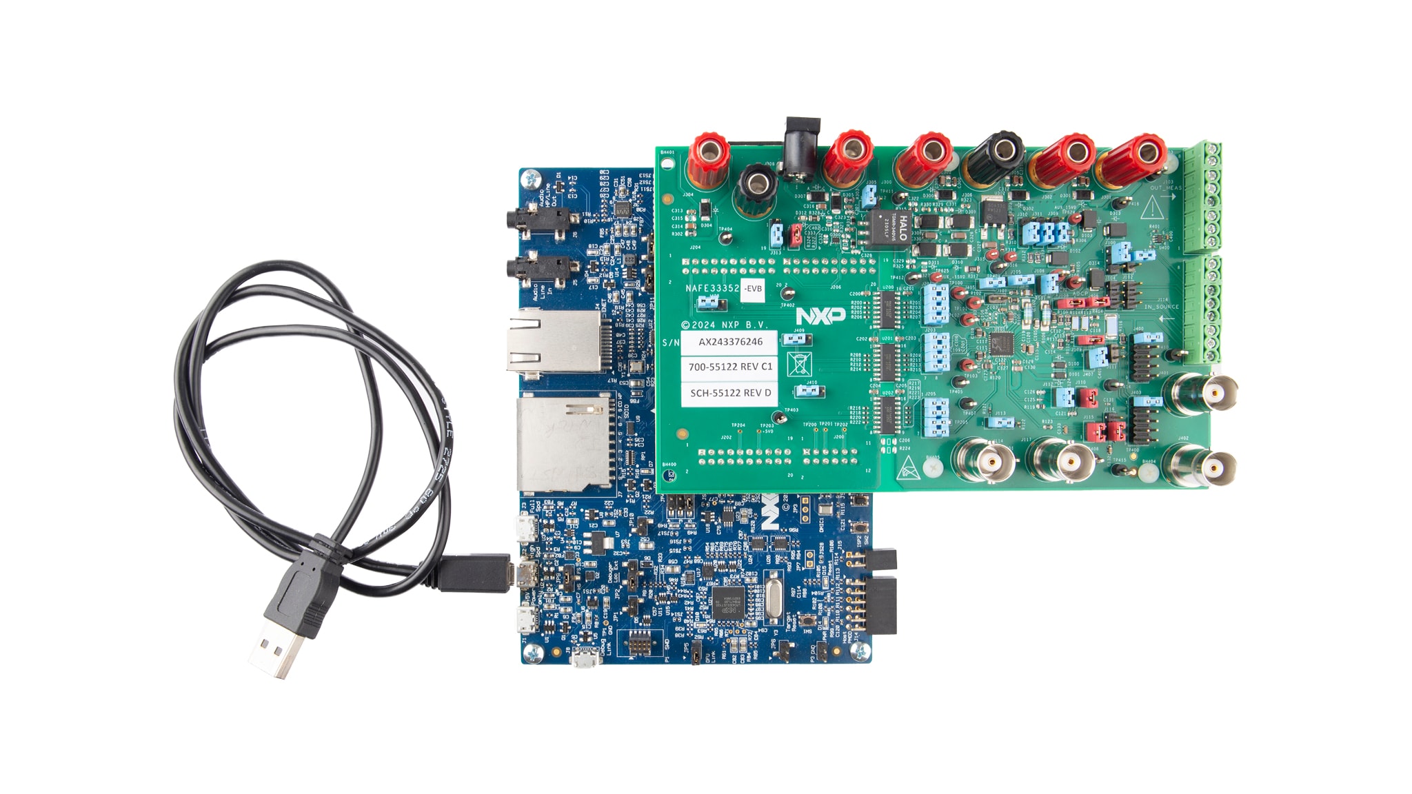
The NAFE33352-EVB contents include:
- Assembled and tested evaluation board in an antistatic bag
1.2 Static Handling Requirements
CAUTION
This device is sensitive to ElectroStatic Discharge (ESD). Therefore care should be taken during transport and handling. You must use a ground strap or touch the PC case or other grounded source before unpacking or handling the hardware.
1.3 Minimum System Requirements
- PC Pentium processor
- One USB port (either 3.0 or 2.0 compatible)
- Windows 7, 8, 10
- OM13098(LPC54628) MCU evaluation board
2. Get Hardware
2.1 Board Features
- Software configurable four analog inputs and 1 analog output
- Easy-to-use GUI-based software demonstrates the capabilities of the NAFE33352
- Onboard transformer to provide DC-DC power supply (+3.3 V, ±15 V) to NAFE33352
- Convenient test points for easy scope measurements and signal access
- USB interface to the host PC
2.2 Board Description
The NAFE33352-EVB evaluation board features a highly configurable, industrial-grade, high precision AIO AFE that meets high-precision measurement requirements. The device is composed of a low-leakage, high-voltage multiplexer, low-offset drift buffers, a low noise and drift PGA, a precision 24-bit sigma delta (ADC), 18-bit DAC and low-drift voltage reference.
2.3 Board Components
Overview of the NAFE33352-EVB board.
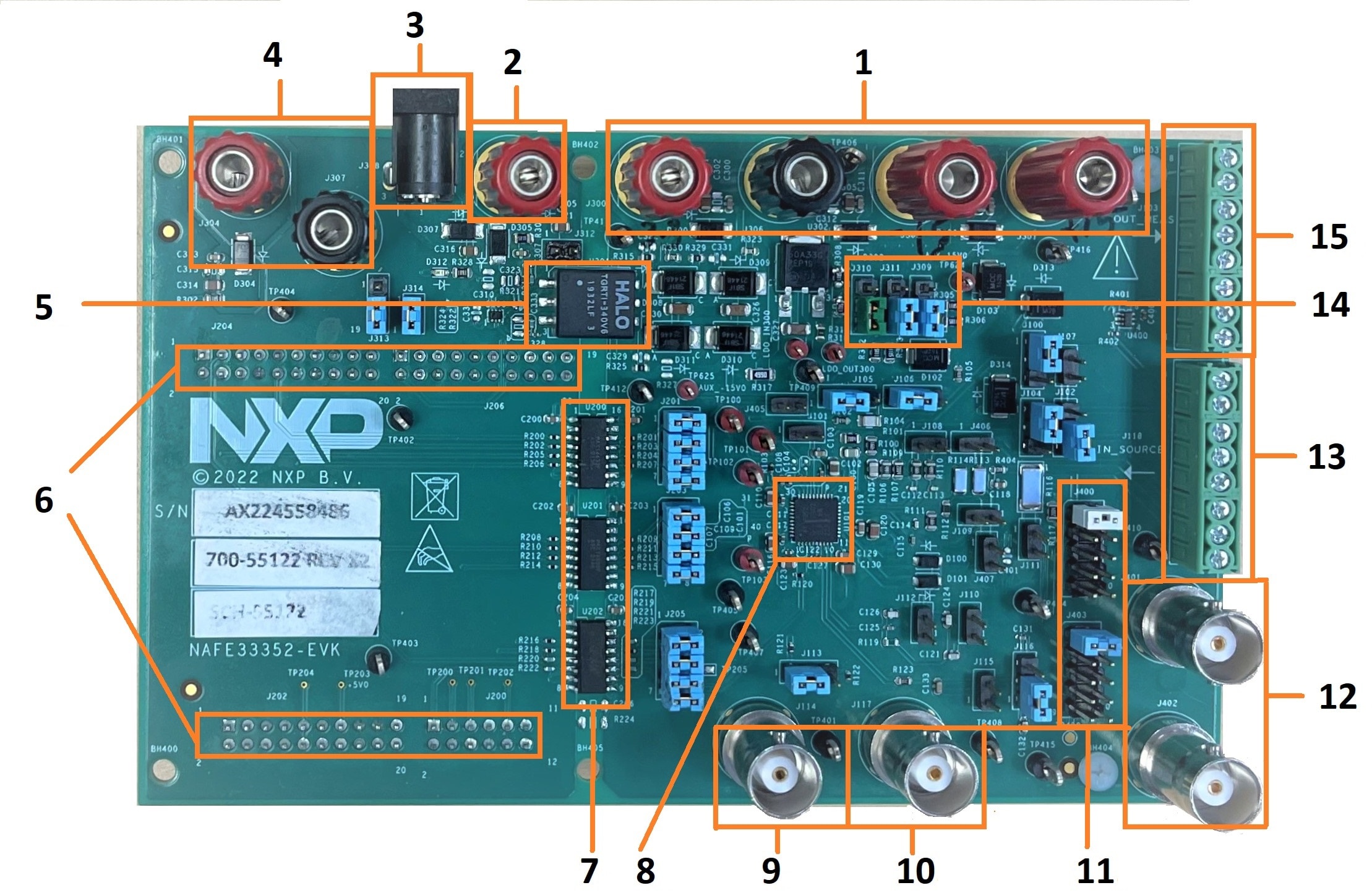
- Banana jack for external power supplies (+3.3 V, +15 V, -15 V) connection for DUT
- Banana jack for external 24 V (single supply connection alternative to three external supplies connection in one)
- Jack connector for 24 V AC-DC power adapter (either this or Step 2 to be used for a single 24 V supply)
- Banana jack for external power supply connection for isolated left DIO (digital IO) section
- DC-DC transformer
- PMOD connector to MCU
- Digital Isolators
- DUT – NAFE33352
- BNC connector for DUT OSCIN pin
- BNC connector for DUT HARTIN pin
- Jumpers to route different signals to external meter
- BNC for external meter connection
- Screw connector to source DUT analog inputs and analog output pins
- 3-way jumpers for power supply source selection
- Screw connector to measure DUT analog inputs and output pins
3. Configure Hardware
3.1 Configure Hardware
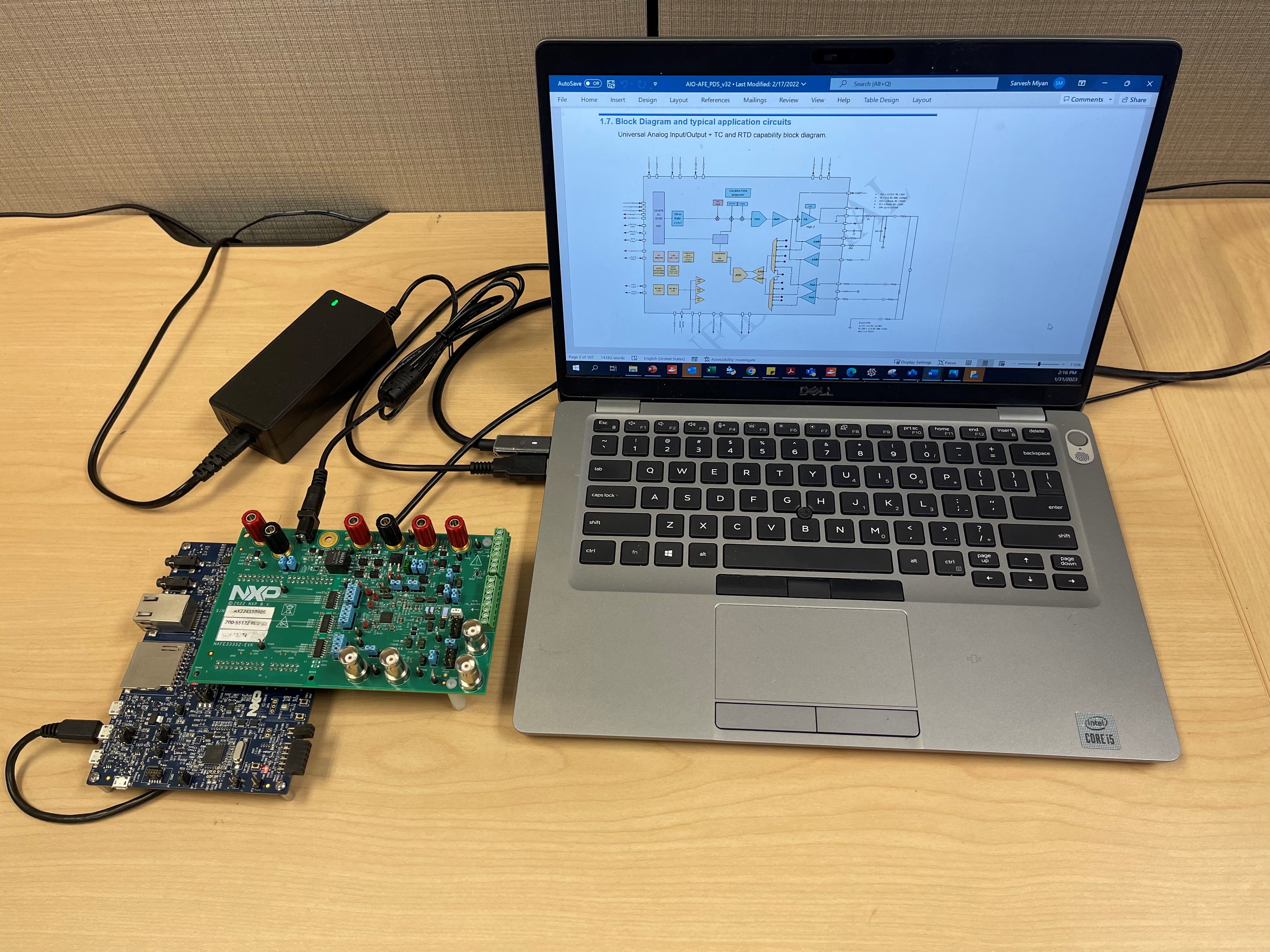
The NAFE33352-EVB evaluation kit includes the NAFE33352-EVB evaluation board, an OM13098 (LPC54628) evaluation board, and a USB cable.
To set up the hardware, do the following:
- Firmly connect the NAFE33352-EVB (AFE) evaluation board to the LPC54628 (microcontroller) evaluation board using the Arduino connectors
- To connect both boards, slide
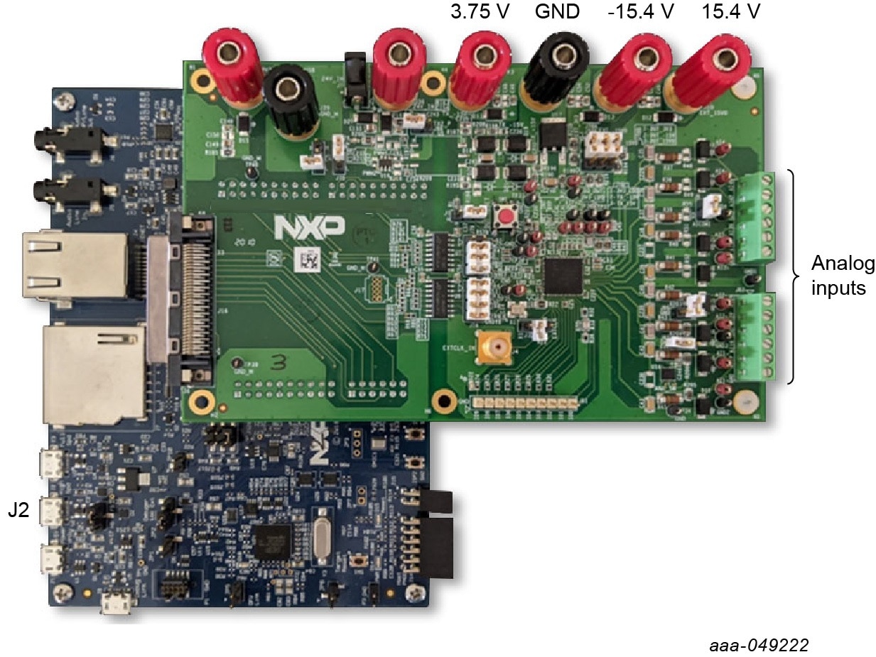
J200,J202,J204andJ206male connectors at the bottom side of the NAFE33352 (AFE) evaluation board into the appropriate female connectors on the LPC54628 (microcontroller) evaluation board - Apply AVDD/DVDD = 3.75 V on
J300, HVDD = +15.4 V onJ301and HVSS = -15.4 V onJ302banana jack connectors and turn on the power supply - Connect USB to μUSB cable between USB port of the computer and
J2(μUSB) port of LPC54628 evaluation board