Getting Started with the RDI7018C3T1
Contents of this document
-
Out of the Box
-
Get Hardware
-
Configure Hardware
Sign in to save your progress. Don't have an account? Create one.
Purchase your RDI7018C3T1
1. Out of the Box
The NXP analog product development boards provide an easy-to-use platform for evaluating NXP products. The boards support a range of analog, mixed-signal and power solutions. They incorporate monolithic integrated circuits and system-in-package devices that use proven high-volume technology. NXP products offer longer battery life, a smaller form factor, reduced component counts, lower cost and improved performance in powering state-of-the-art systems.
This page will guide you through the process of setting up and using the RDI7018C3T1 board.
1.1 Kit Contents and Packing List
The kit contents include:
- Assembled and tested evaluation board/module in antistatic bag
- Three cell terminal cables
- One transport protocol link (TPL) communication cable
- Quick start guide
1.2 Additional Hardware
To use this kit, the following hardware is required:
- A 4-cell to 18-cell battery pack or a battery pack emulator, such as BATT-18EMULATOR
- A TPL communication system
- The evaluation setup consists of the FRDM665SPIEVB (EVB for MC33665A) with the S32K3X4EVB-T172 (S32K3 MCU)
- For the evaluation setup, EvalGUI 7 is available
2. Get Hardware
2.1 Kit Overview
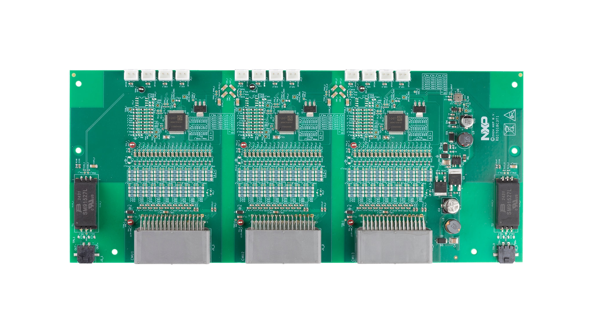
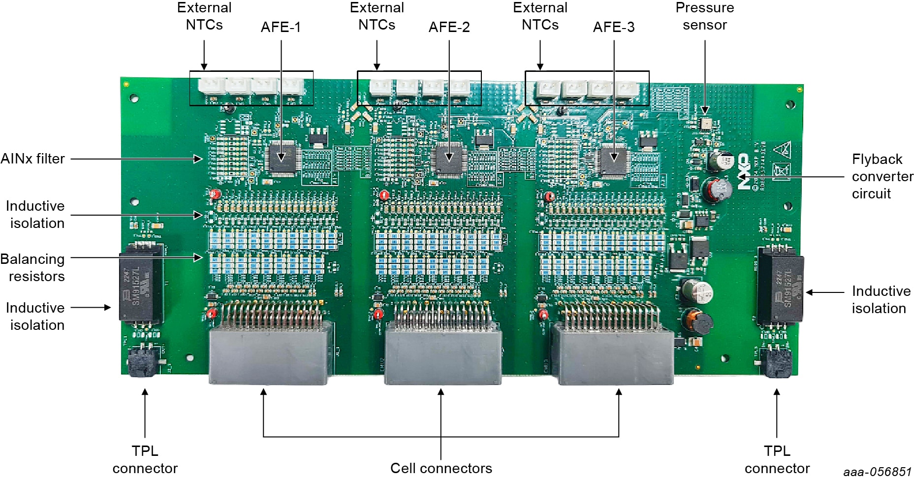
The RDI7018C3T1 is a hardware evaluation tool supporting the NXP BMI7018 device. The RDI7018C3T1 implements three BMI7018 battery cell controller ICs. The BMI7018 is a battery cell controller that monitors up to 18 Li-ion battery cells. It is designed for use in industrial applications. The device performs analog‑to‑digital conversions on the differential cell voltages. It is also capable of temperature measurements and can forward communication via an I²C-bus to other devices. The RDI7018C3T1 is an ideal platform for rapid prototyping of BMI7018 based applications that involve voltage and temperature sensing.
The RDI7018C3T1 measures the pressure of the battery module using the onboard FXPS7250A4ST1 pressure sensor. The RDI7018C3T1 converts the battery module voltage to 12 V using the TEA1721AT/N1,118 flyback controller, then converts the 12 V to 5 V to supply the pressure sensor.
The RDI7018C3T1 uses inductive isolation for offboard communication. The galvanic isolation for onboard communication is established via capacitors.
3. Configure Hardware
3.1 Battery Emulator Connection
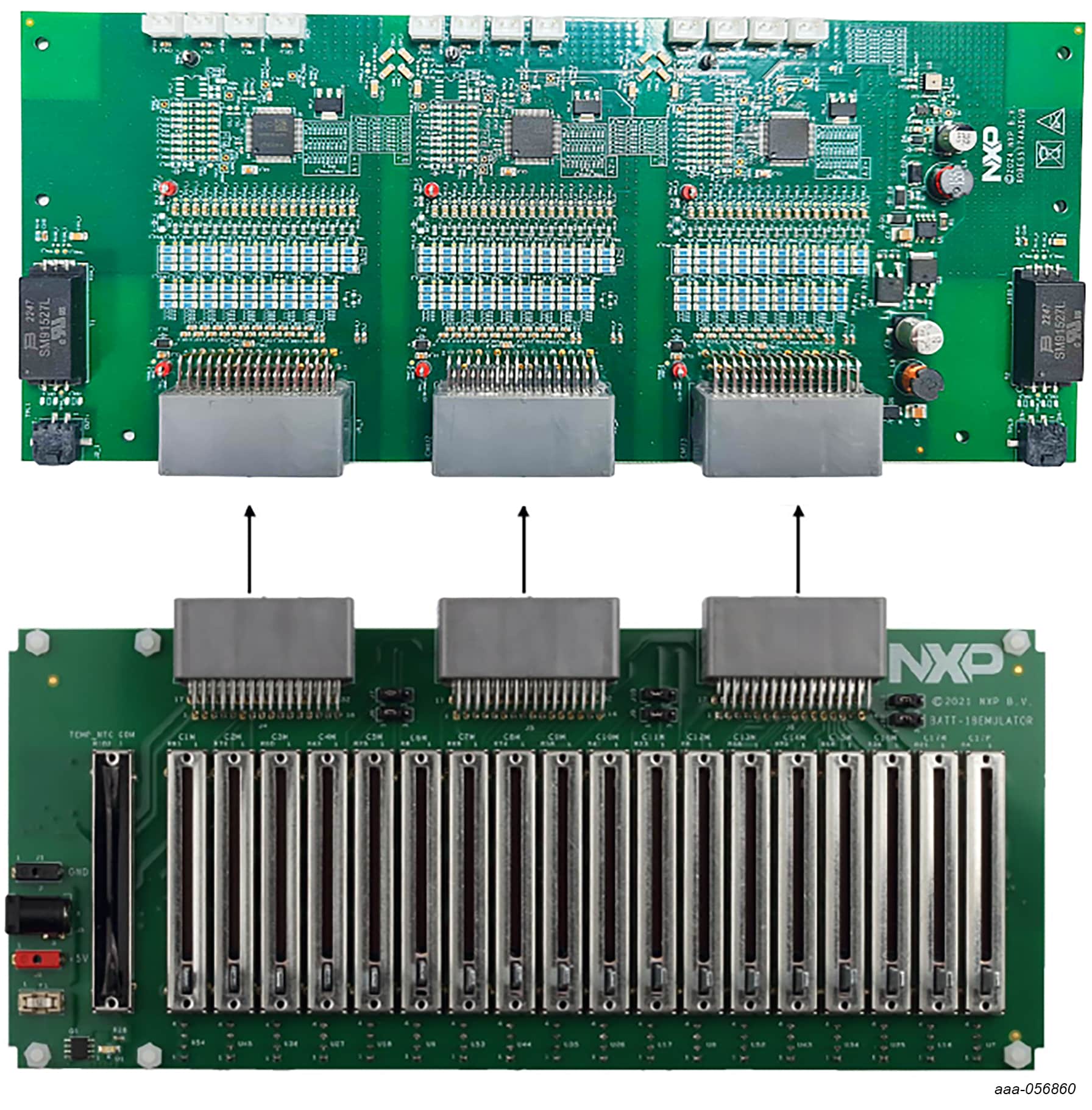
One BMI7018 can monitor a minimum of four cells and a maximum of 18 cells. NXP
provides an 18‑cell battery emulator board, BATT-18EMULATOR. This board
provides an intuitive way to change the voltage across any of the 18 cells of
an emulated battery pack. The board RDI7018C3T1 can be connected to an 18‑cell
battery emulator board using the connectors J1_1,
J1_2 and J1_3 with the provided supply cables; see
Figure 2.
3.2 TPL Communication Connection
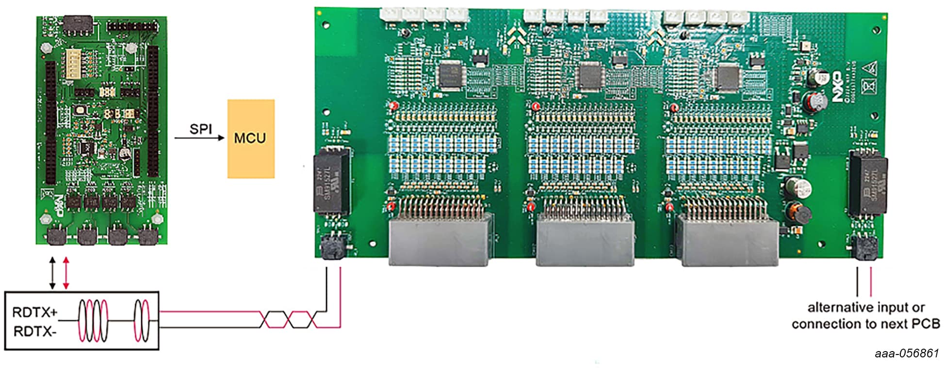
In a high-voltage isolated application with a daisy chain configuration, up to 21 RDI7018C3T1 boards can be connected.
The TPL connections use the COMM connectors J1 and J2 of the FRDM665SPIEVB and
J2_1 and J2_1 of the RDI7018C3T1.
Design Resources
Board Information
Additional References
In addition to our RDI7018C3T1 page, you may also want to visit: