Getting Started With the S32K344 Motor Control Development Kit for High-Power 48 V Applications
Contents of this document
-
Out of the Box
-
Get Software
-
Plug It In
-
Build, Run
Sign in to save your progress. Don't have an account? Create one.
Purchase your S32K344 Motor Control Development Kit for High-Power 48 V Applications
1. Out of the Box
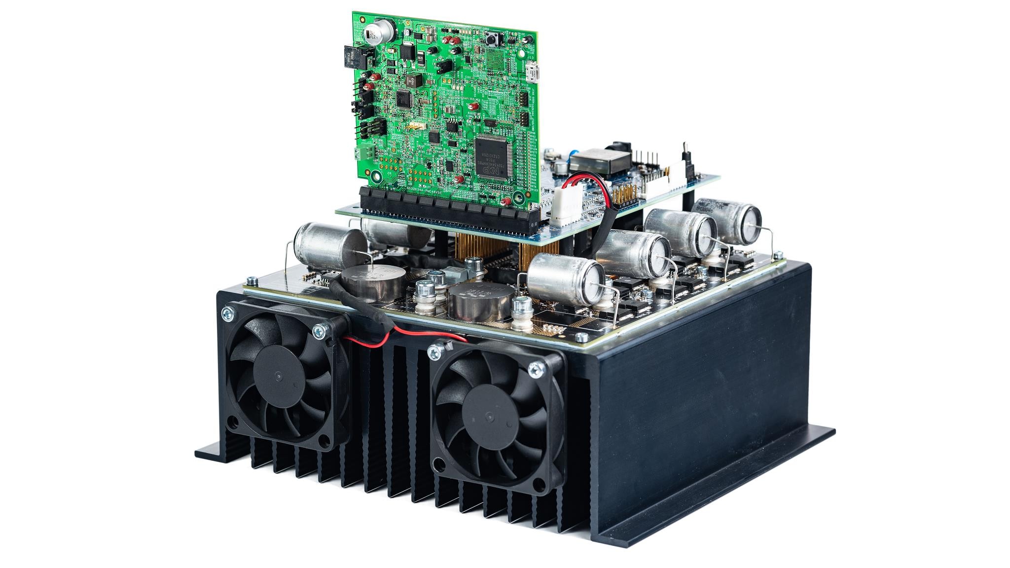
1.1 Get to Know the MC_XTM4CK344 Devkit

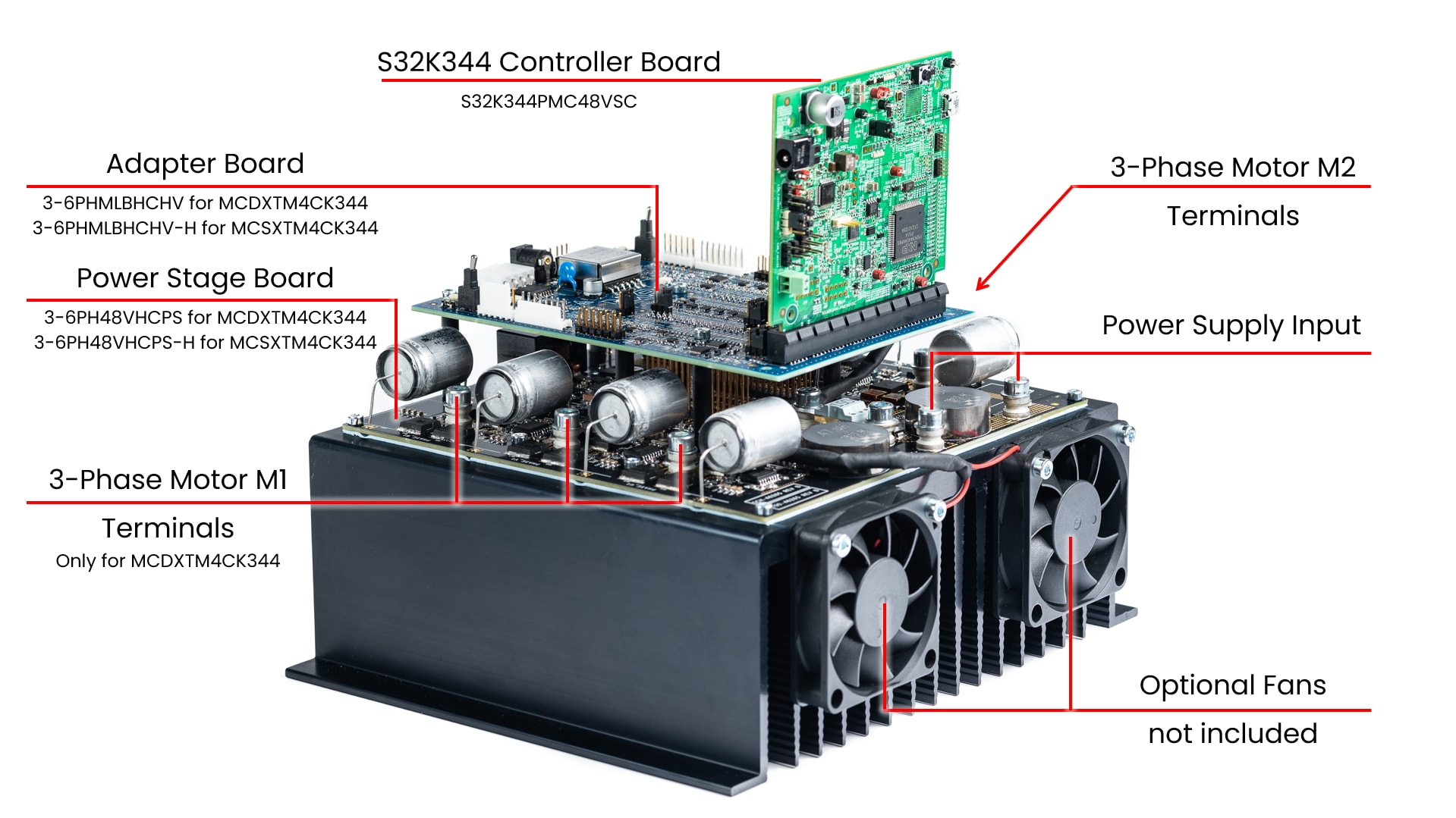
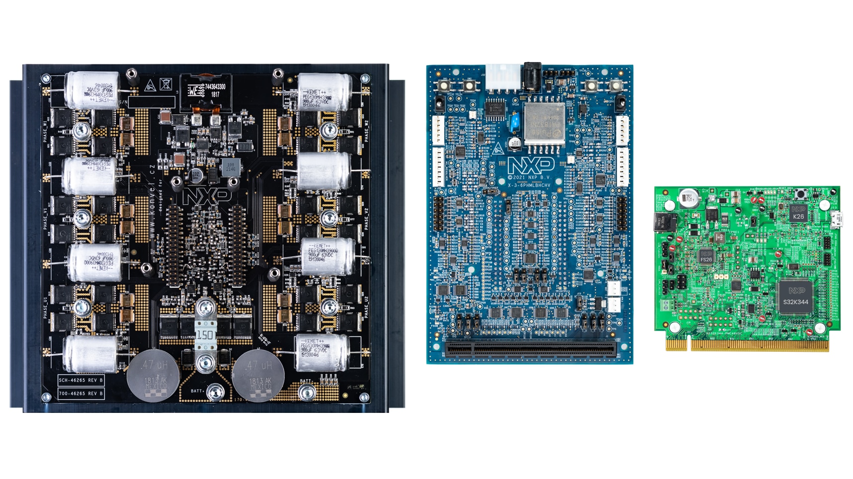
MC_XTM4CK344 Content:
- 3-6PH48VHCPS(-H) Power Stage Board
- 3-6PHMLBHCHV(-H) Adapter Board
- S32K344PMC48VSC Controller Board
- Mounting screws
2. Get Software
Sign in at nxp.com with your credentials.
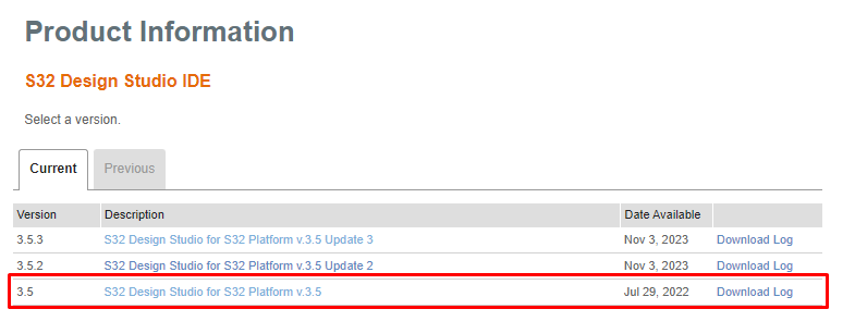
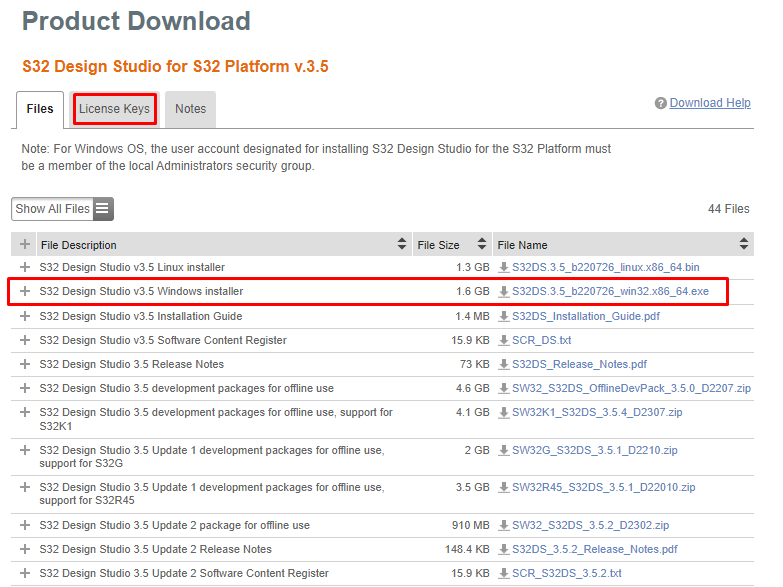
2.1 Download and Install IDE
Download and install S32 Design Studio for S32 Platform
Download S32DS IDE
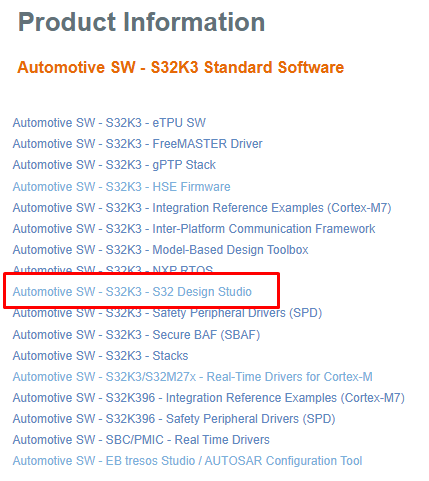
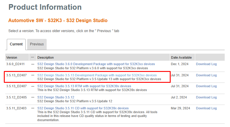
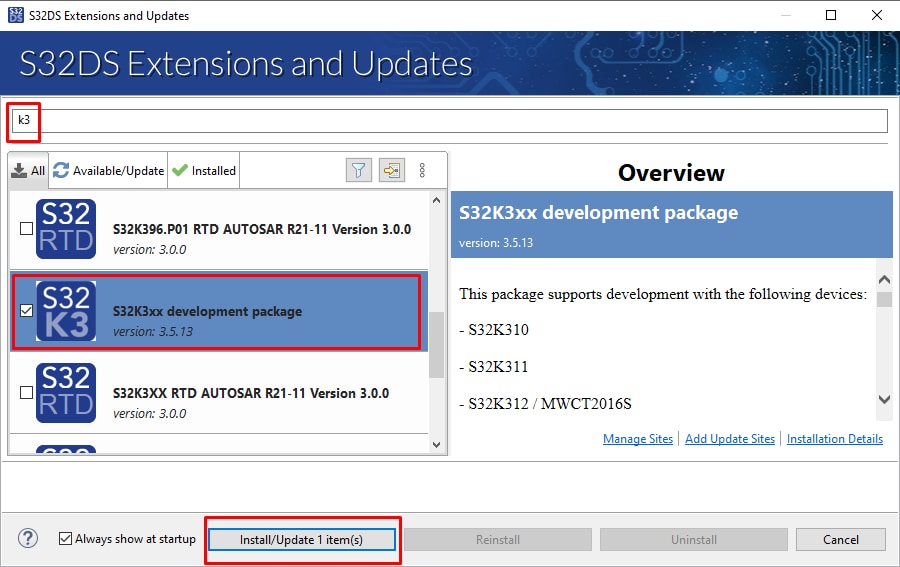
2.2 Download S32K3xx Developmet Package
The S32K3 Development Package for S32DS may be updated directly from S32DS, but sometimes it might be necessary to download it and install it manualy
To download S32K3 Development Package for S32DS V3.5, go to S32K3 Standard SW Package
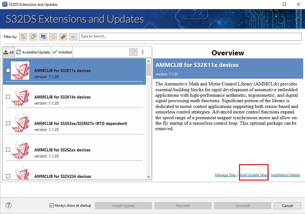
2.3 Install the S32K3 Development Package
- In S32DS, go to Help → S32DS Extensions and Updates, and from the top menu, open the S32DS Extensions and Updates dialogue where the Add Update Sites link appears
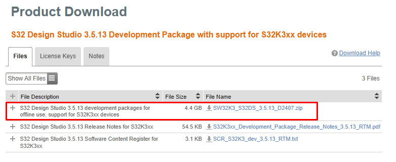
- Select downloaded
SW32K3_S32DS_3.5.13_D2407.zipfile - Install S32K3 Development Package
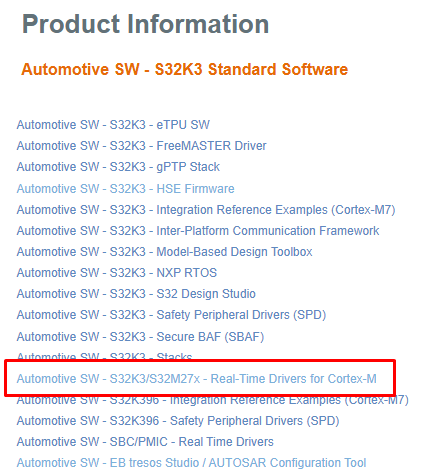
2.4 Download the RTD Drivers
Download RTD for S32K3 and S32M27x version 4.0.0. by selecting the Automotive SW - S32K3/S32M27x - Real-Time Drivers for Cortex-M package to download update site file
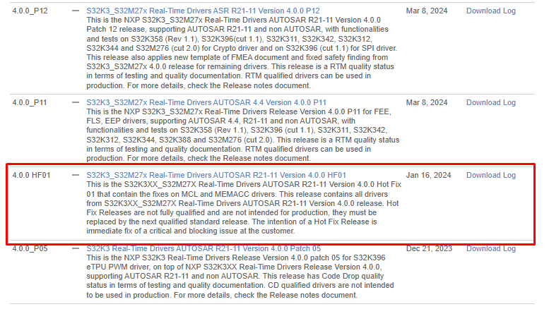
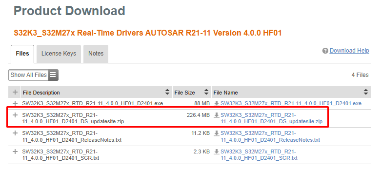
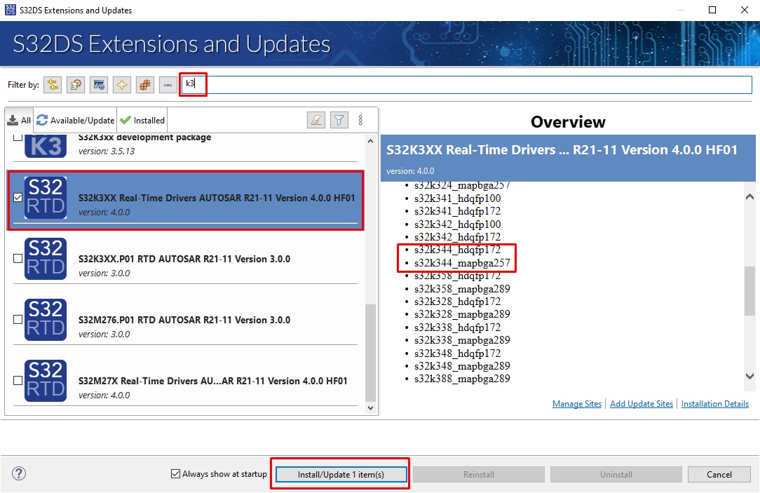
2.5 Install the RTD Drivers to S32DS
- In S32DS, go to Help → S32DS Extensions and Updates, and from the top menu, open the S32DS Extensions and Updates dialogue where the Add Update Sites link appears
- Select downloaded file named
SW32K3_S32M27x_RTD_R21-11_4.0.0_HF01_D2401_DS_updatesite.zip - Install the RTD 4.0.0 HF01 from the list, but ensure that you select the version that supports only/also S32K344 as the RTD 4.0.0 may appear on the list more than twice
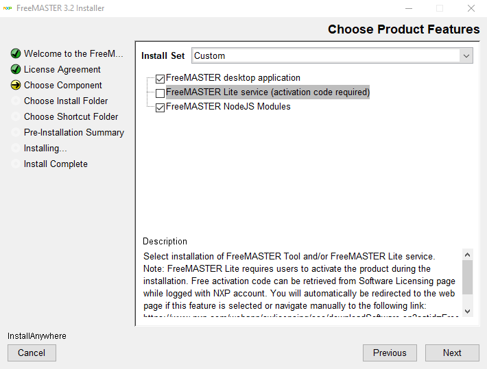
2.6 Get FreeMASTER Application Tool
Download and install FreeMASTER application tool for real-time debugging
TIP: for this setup you may skip the Lite service installation (for which the activation code is required)
2.7 Get Automotive Motor Control Library (AMMCLib) for S32K3
Download and install AMMCLib for S32K3 (version 1.1.41 or newer)
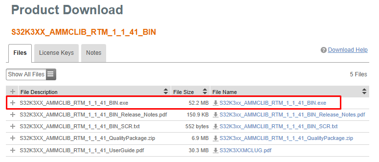
TIP: If possible, install AMMCLib in its default path location for easy path modification
2.8 Get the or MC_XTM4CK344 Motor Control Application
Download and install the MC_XTM4CK344 motor control application software (MC_XTM4CK344_SW.exe)
3. Plug It In
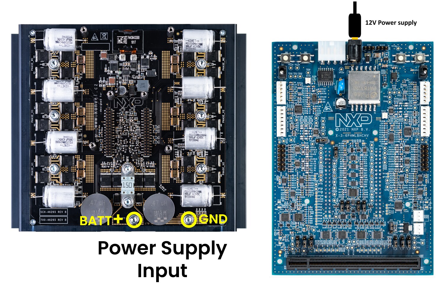
NXP does not provide 48 V motor(s) or a power supply within MC_XTM4CK344 kit, however you may use any suitable 3 ph motor(s) and 24/48 V power supply.
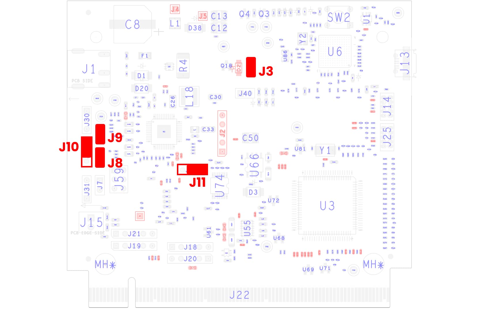
3.1 Default Jumpers
Check The Default Jumper positions at the Controller board
| Jumper | State | Notes |
|---|---|---|
J3 |
CLOSED | FS26_VDEBUG signal connected from OpenSDA 5 V |
J8 |
CLOSED | 5V power domain routed from FS26_VLDO1 |
J9 |
CLOSED | 3V3 power domain routed from FS26_VLDO2 |
J10 |
1-2 | VDDA power domain routed from FS26_VTRK1 (5 V) |
J11 |
1-2 | TJA1101 CONFIG0 pin tight with pull-up - PHY configured as Master |
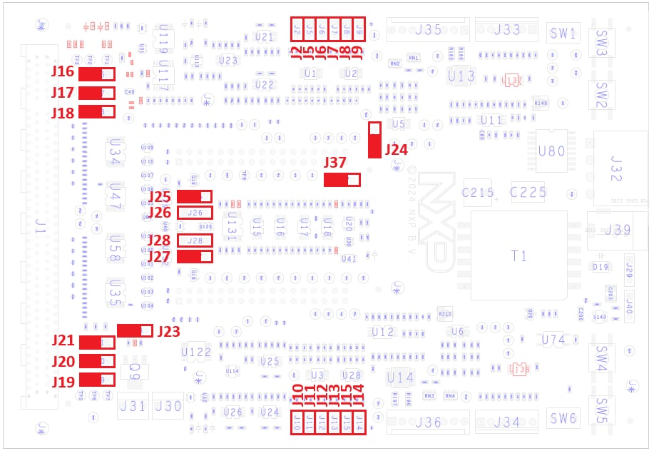
Check The Default Jumper Positions at the Adapter board
| Jumper | State | Notes |
|---|---|---|
J2, J5..J9 |
OPEN | M1 current sense amplifier gain = 50 (Not Applicable for MCSXTM4CK344) |
J10..J15 |
OPEN | M2 current sense amplifier gain = 50 |
J16 |
2-3 | M1 FOC configuration, I_PHA routed to AN1 signal (Not Applicable for MCSXTM4CK344) |
J17 |
2-3 | M1 FOC configuration, I_PHB routed to AN3 signal (Not Applicable for MCSXTM4CK344) |
J18 |
2-3 | M1 FOC configuration, I_PHC routed to AN5 signal (Not Applicable for MCSXTM4CK344) |
J19 |
2-3 | M2 FOC configuration, I_PHF routed to AN29 signal |
J20 |
2-3 | M2 FOC configuration, I_PHE routed to AN27 signal |
J21 |
2-3 | M2 FOC configuration, I_PHD routed to AN25 signal |
J23 |
1-2 | Fan(s) controlled by MCU |
J24 |
1-2 | Overcurrent and Overvoltage Fault logic: Voltage reference V-TH derived from VREF |
J25 |
1-2 | M1 Safe state activation by internal HW logic: safe open state (Not Applicable for MCSXTM4CK344) |
J26 |
OPEN | M1 Safe state activation by External ECU: safe open state - not active (Not Applicable for MCSXTM4CK344) |
J27 |
1-2 | M2 Safe state activation by internal HW logic: safe open state |
J28 |
OPEN | M2 Safe state activation by External ECU: safe open state - not active |
J37 |
1-2 | M1_RESET: reset of the Buck UV latched fault for motor 1 (Not Applicable for MCSXTM4CK344) |
| 2-3 | M2_RESET: reset of the Buck UV latched fault for motor 2 |
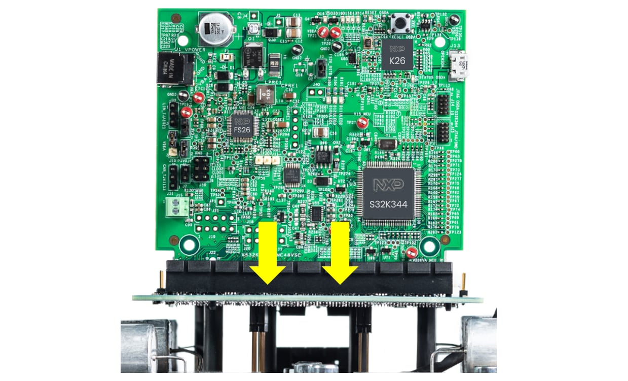
3.2 Assemmbly Kit
Plug the Adapter board to the Power Stage board via header conector(s)
The mounting holes (6) will help you with alignment
Use plastic screws to secure the mechanical setup of Adapter and Power Stage boards
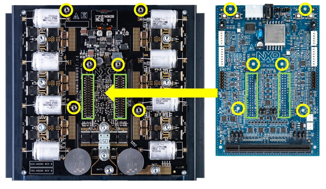
Insert Controller board into the PCIe connector at the Adapter board
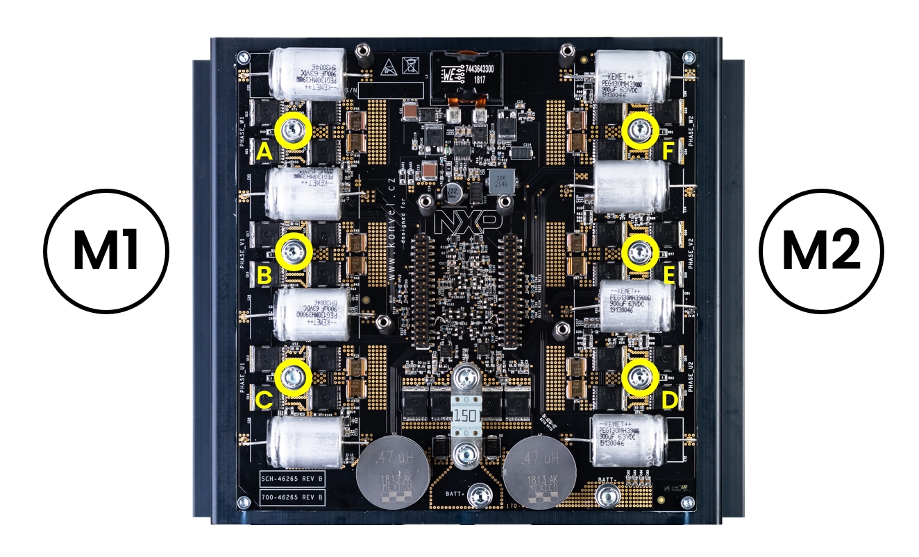
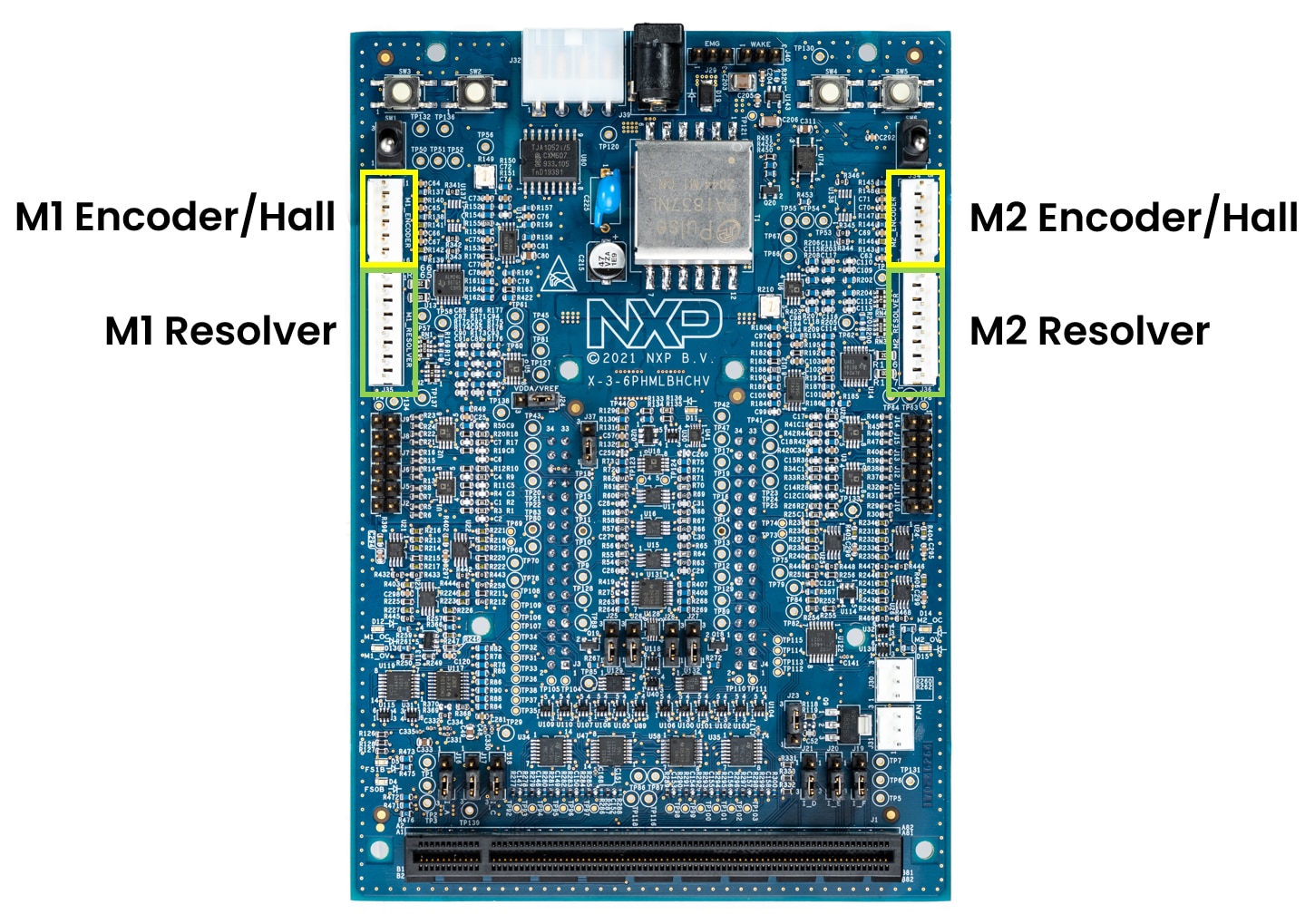
3.3 Connect the Motor
Connect the motor M2 (&M1) phase wires to the power stage board via appropriate M4 screws
Optionally, plug the Resolver or Encoder/HALL position sensors (used only with sensor-based sw application)
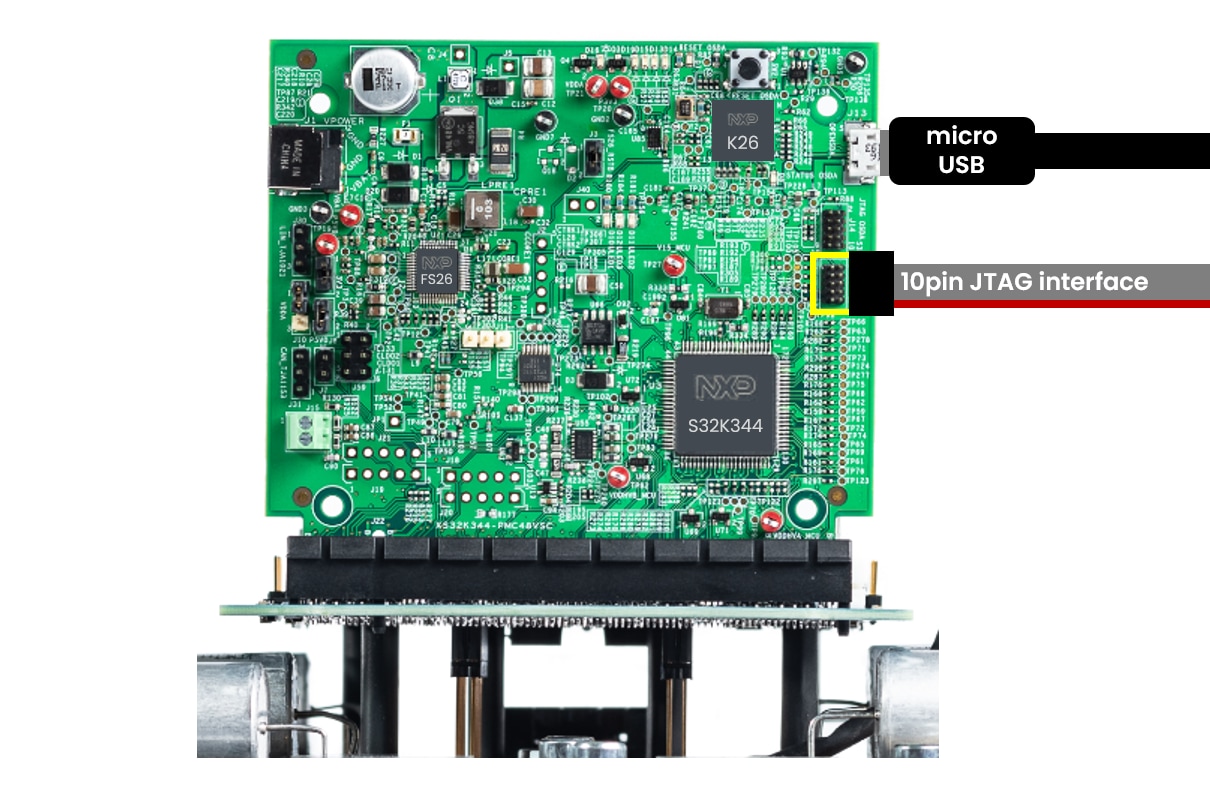
3.4 Plug the Debugger
Plug the micro USB cable to the S32K3 on-board debugger or use the external 10pin JTAG debug interface to connect with PC
4. Build, Run
Let's take your MC_XTM4CK344 motor control kit for a test drive.
4.1 Select Application and Project Import
Select the appropriate motor control application from the installed directory
NXP\MC_DevKits\MC_XTM4CK344\sw
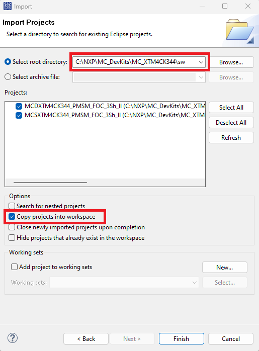
To import the installed application software project in the S32 Design Studio IDE for S32 Platform:
- Launch S32DS for S32 Platform
- Go to File → Import , then select General → Existing Projects into Workspace

Navigate to the installed application directory: NXP\MC_DevKits\MC_XTM4CK344\sw and choose appropriate project and click OK, then click Finish
4.2 Use Configuration Tool
Unfold the structure of the project with low-level drivers by double-clicking on *.mex file to open the project configuration in the Configuration Tool
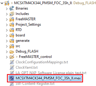
Please ensure that you configure appropriate project and click on "Update Code" button for generating configuration files

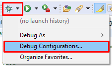
4.3 Upload Software and Debug
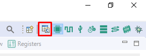
In S32DS, return to the C/C++ perspective
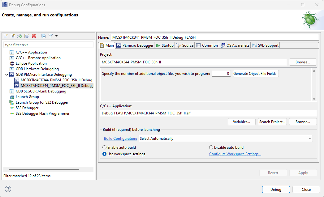
Go to the Debug Configuration menu and select the predefined debug configuration for building and uploading software into microcontroller unit (MCU)
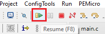
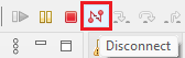
The S32DS will switch to debug perspective where you can let the code run by clicking on Resume (or press F8), and select Disconnect to avoid interference between the S32DS IDE debugger and the FreeMASTER tool
4.4 Set Up the Debugging Tool
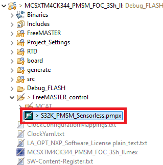
Launch the FreeMASTER application
To open the *.pmpx FreeMASTER project <selected project>\FreeMASTER_control, click File → Open Project
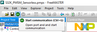
Launch the FreeMASTER application
To enable communication, click Go (or press Ctrl+G) in the FreeMASTER tool bar
Successful communication displays in the status bar at the bottom as:
"RS-232 UART Communication;COMn;speed = 115200"
Application Control
Let's take your MC_XTM4CK344 motor control board for a test drive.
Motor Parameters
Now you may edit the motor parameters according to connected BLDC/PMSM motor(s). In the Motor Control Application Tuning (MCAT) Tool switch to Parameters tab and edit values on left side.
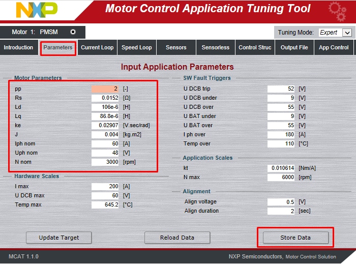
Once you finish, click on Store Data, switch to Output File tab and Generate static configuration file.
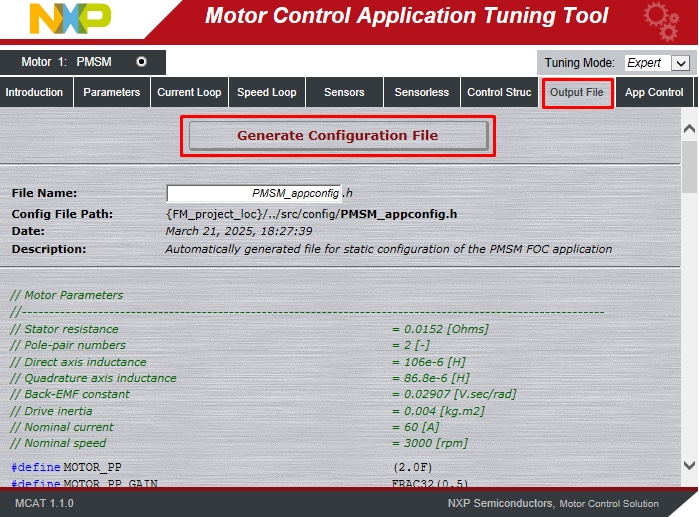
Now repeat step 4.3 to build the project and upload the code into MCU.
Spin the Motor
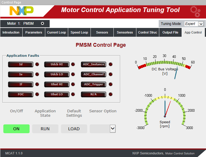
Click the App Control tab on the Motor Control Application Tuning (MCAT) Tool menu to display the application control page.
Configure the motor rpms and turn on the motor drive.
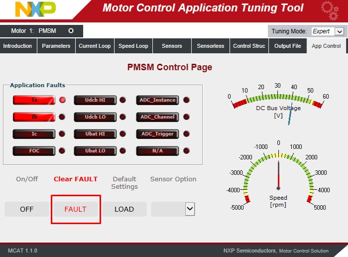
Check pending faults
In case of pending faults (fault state - blinking LED), click the Clear FAULT on the FreeMASTER MCAT control page or alternatively press and simultaneously hold SW4 and SW5 for M2 (SW2 and SW3 for M1) on the adapter board.
Start application
Click On/Off on the control page or press SW4/SW5 or switch SW6 for M2 (SW2/SW3 or switch SW1 for M1) on the adapter board to initiate clockwise/counterclockwise spinning of the rotor. Run state is signalized by steadily glowing LED. Set speed.
Change the speed required variable to set the speed. Go to the Variable Watch window and modify Speed Required variable or click on the speed gauge, or by pressing the switch SW4/SW5 (SW2/SW3).
Stop application
Stop the application by clicking On/Off button on the FreeMASTER MCAT control page or switch the SW6 (SW1 for M1) on the adapter board. At ready state LEDs are turned off.
Design Resources
Board Assets
Application Documents
Software
-
MC-XTM4CK344 Development Kit Application Software
- S32K3 Standard Software
- S32K3 Reference Software
- S32 Design Studio IDE
- Real-Time Drivers (RTD)
- S32K Power Estimation Tool (PET)
- Model-Based Design Toolbox (MBDT)
- Structural Core Self-Test (SCST) Library
- FreeMASTER Run-Time Debugging Tool
- Inter-Platform Communication Framework (IPCF)
- Automotive Math and Motor Control Library (AMMCLib)
- S32 Safety Software Framework (SAF) and Safety Peripheral Drivers (SPD)
Support
Forums
Connect with other engineers and get expert advice on designing with the MCSXTM4CK344/MCDXTM4CK344 on one of our community sites.
On this page
- 2.1
Download and Install IDE
- 2.2
Download S32K3xx Developmet Package
- 2.3
Install the S32K3 Development Package
- 2.4
Download the RTD Drivers
- 2.5
Install the RTD Drivers to S32DS
- 2.6
Get FreeMASTER Application Tool
- 2.7
Get Automotive Motor Control Library (AMMCLib) for S32K3
- 2.8
Get the or MC_XTM4CK344 Motor Control Application
- 3.1
Default Jumpers
- 3.2
Assemmbly Kit
- 3.3
Connect the Motor
- 3.4
Plug the Debugger
- 3.5
Connect Power Supply