Getting Started with the SC18IS606-EVB Evaluation Board
Contents of this document
-
Get Started
-
Get Hardware
-
Configure Hardware
Sign in to save your progress. Don't have an account? Create one.
Purchase your SC18IS606-EVB: I2C to SPI Bridge Evaluation Board
1. Get Started
The NXP analog product development boards provide an easy-to-use platform for evaluating NXP products. The boards support a range of analog, mixed-signal and power solutions. They incorporate monolithic integrated circuits and system-in-package devices that use proven high-volume technology. NXP products offer longer battery life, a smaller form factor, reduced component counts, lower cost and improved performance in powering state-of-the-art systems.
This page will guide you through the process of setting up and using the SC18IS606-EVB evaluation board.
1.1 Kit Contents and Packing List
The SC18IS606-EVB contents include:
- Assembled and tested evaluation board in an anti-static bag
1.2 Additional Requirements
- External power supply
- External host system with I²C controller
2. Get Hardware
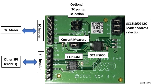
2.1 Board Features
- 6-pin 100 mil spacing I²C interface header (
JP2) - On-board SPI EEPROM which can be directly accessed by the external I²C controller via the SC18IS606
- 7-pin 100 mil spacing SPI interface header (
JP1) to allow other SPI devices to be connected to the evaluation board to be accessed via the SC18IS606
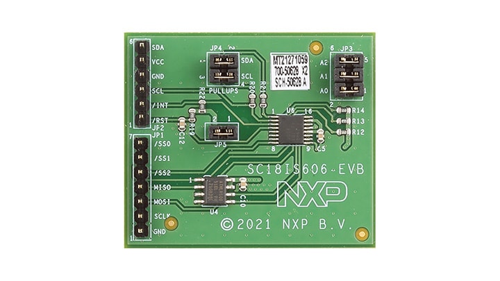
2.2 Board Description
The SC18IS606-EVB evaluation board is designed to be connected to an external I²C controller via a 6-pin male (JP2) header. The SC18IS606-EVB evaluation board has a non-board SPI target serial EEPROM, which can be directly accessed by the external I²C controller via SC18IS606. The external I²C controller
can write, read and program the serial EEPROM without requiring an SPI target to be connected to the board.
The 3V3 power for the SC18IS606-EVB evaluation board should be supplied via this I²C interface header as well.
The SC18IS606-EVB evaluation board also has an SPI interface header (JP1) to allow other SPI target devices to be connected to the evaluation board. These SPI
target devices can be accessed directly by the I²C controller via the SC18IS606 I²C to SPI bridge.
2.3 Board Components
3. Configure Hardware
3.1 Configure the Hardware
- Connect 3.3 V to
JP2pin 5 - Connect external I²C controller to
JP2pin 6 (SDA) andJP2pin 3 (SCL) - Connect ground to
JP2pin 4 - If interrupt is supported, connect interrupt signal to
JP2pin 2 - SC18IS606 is reset up on POR but can be reset externally via
JP2pin 1 - The board is powered and SC18IS606 can be accessed via I²C target address 0x50
Design Resources
Board Information
Additional Information
In addition to our SC18IS606: I²C-Bus to SPI Bridge page, you may also want to visit:
- UART pages: SC16IS740_750_760, SC16IS741
- Hardware pages: Analog toolbox