Secure Automotive Network Design Guide
Contents of this document
-
Out of the Box
-
Get Software
-
Plug It In
Sign in to save your progress. Don't have an account? Create one.
Purchase your S32K324 Triple PMSM Control Reference Design Board
1. Out of the Box
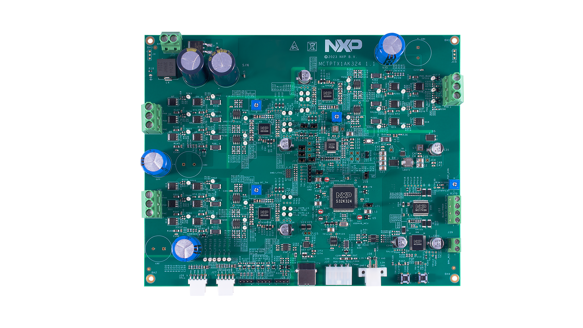
1.1 Get to Know the MCTPTX1AK324 Reference Design Board
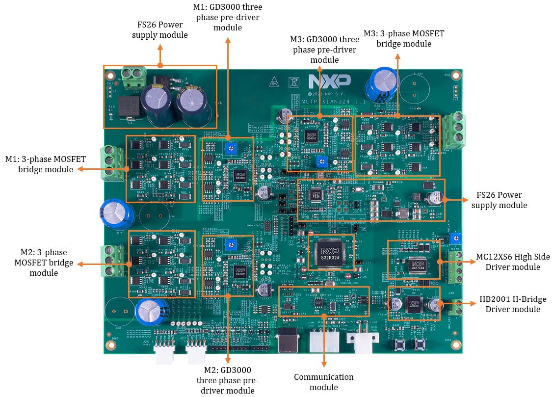
1.2 Block Diagram Features

2. Get Software
You can watch the video or follow the below step-by-step guide to set up your MCTPTX1AK324 Evaluation Board:
2.1 Download the Development Kit - Application Software
The software package includes projects for most typical hardware configurations.
2.2 Get the Integrated Development Environment (IDE)
Download and install S32 Design Studio IDE for S32 Platform
Download S32 DESIGN STUDIO IDE
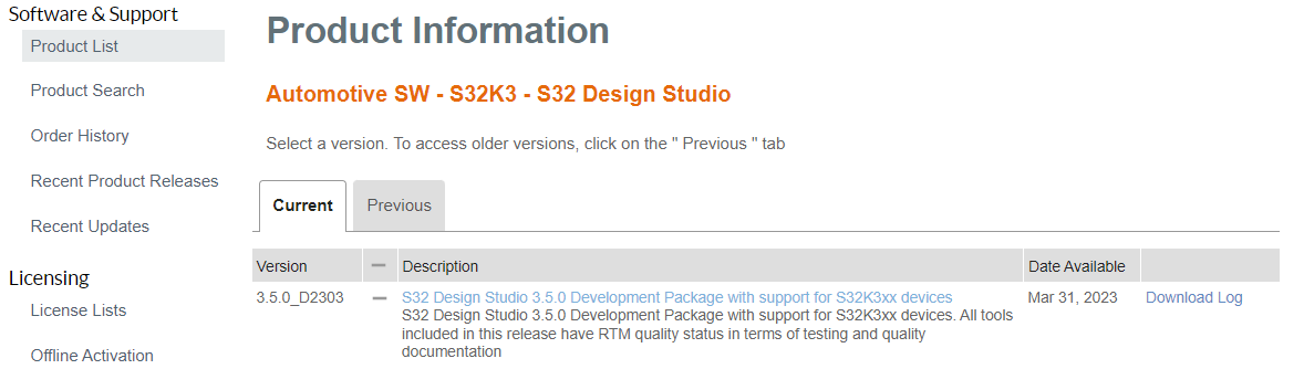
2.3 Get the Development Packages
All development packages are available from S32K3 Standard Software Package.
Download and install the latest version of S32K3xx Development Package.
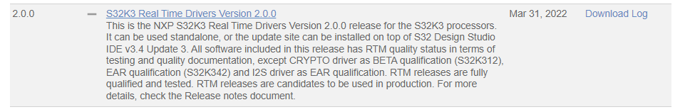
Download and install S32K3xx Real-Time Drivers Version 2.0.0 package.
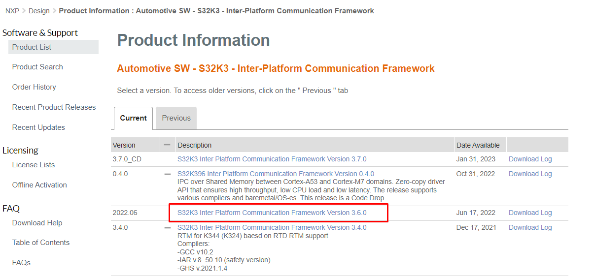
Download and install IPCF package to support S32K324 dual-core communication.
2.4 Get Automotive Math and Motor Control Library (AMMCLib)
We strongly recommend the latest version of the Automotive Math and Motor Control Library (AMMCLib)
2.5 Get the Run-Time Debugging Tool
MCTPTX1AK324 performs better when using the FreeMASTER Run-Time Debugging Tool.
The FreeMASTER communication driver for S32K3 microcontrollers is also needed. Download it from the Automotive SW - S32K3 - S32 FreeMASTER link in the S32K3 Standard Software Package.
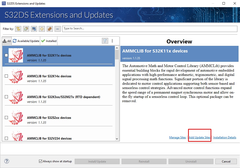
Open S32DS Extensions and Updates dialog (menu -> Help -> S32DS Extensions and Updates), click on Add Update Sites link and navigate to FreeMASTER communication driver for S32K3 (zip file starting with "com.") on your disk.
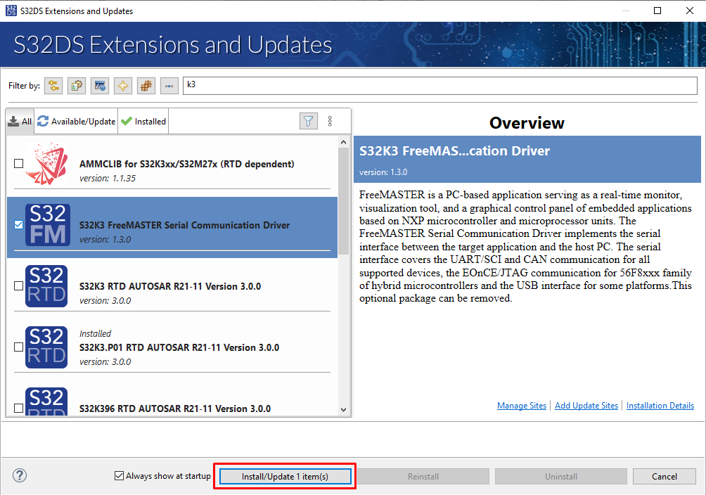
Install FreeMASTER communication driver for S32K3.
3. Plug It In
3.1 Check the Default Jumper Positions In the MCTPTX1AK324 Evaluation Board
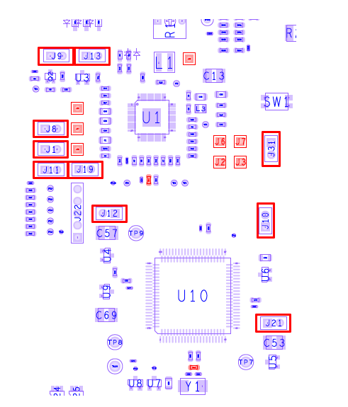
| Default Jumper settings | ||
|---|---|---|
| Jumper | State | Notes |
J1 |
CLOSED | 5 V for UART to USB |
J8 |
CLOSED | 5 V for CAN PHY |
J9 |
CLOSED | Enable FS26 debug mode |
J10 |
CLOSED | FS26 VCore 1.5 V for MCU VCore |
J11 |
CLOSED | FS26 LDO2 5.0 V for 5.0 V devices |
J12 |
CLOSED | MCU VDD_HV_A supply input |
J13 |
CLOSED | Enable FS26 debug mode |
J19 |
CLOSED | FS26 LDO1 5.0 V for 5 V devices |
J21 |
CLOSED | MCU VDD_HV_B supply input |
J31 |
OPEN | FS26 wake inputs |
3.2 GD3000 Overcurrent Compare Setting
Make sure the potentiometer for overcurrent comparator is set in position (slightly to the left from the middle) for approximately 8 – 10 A.
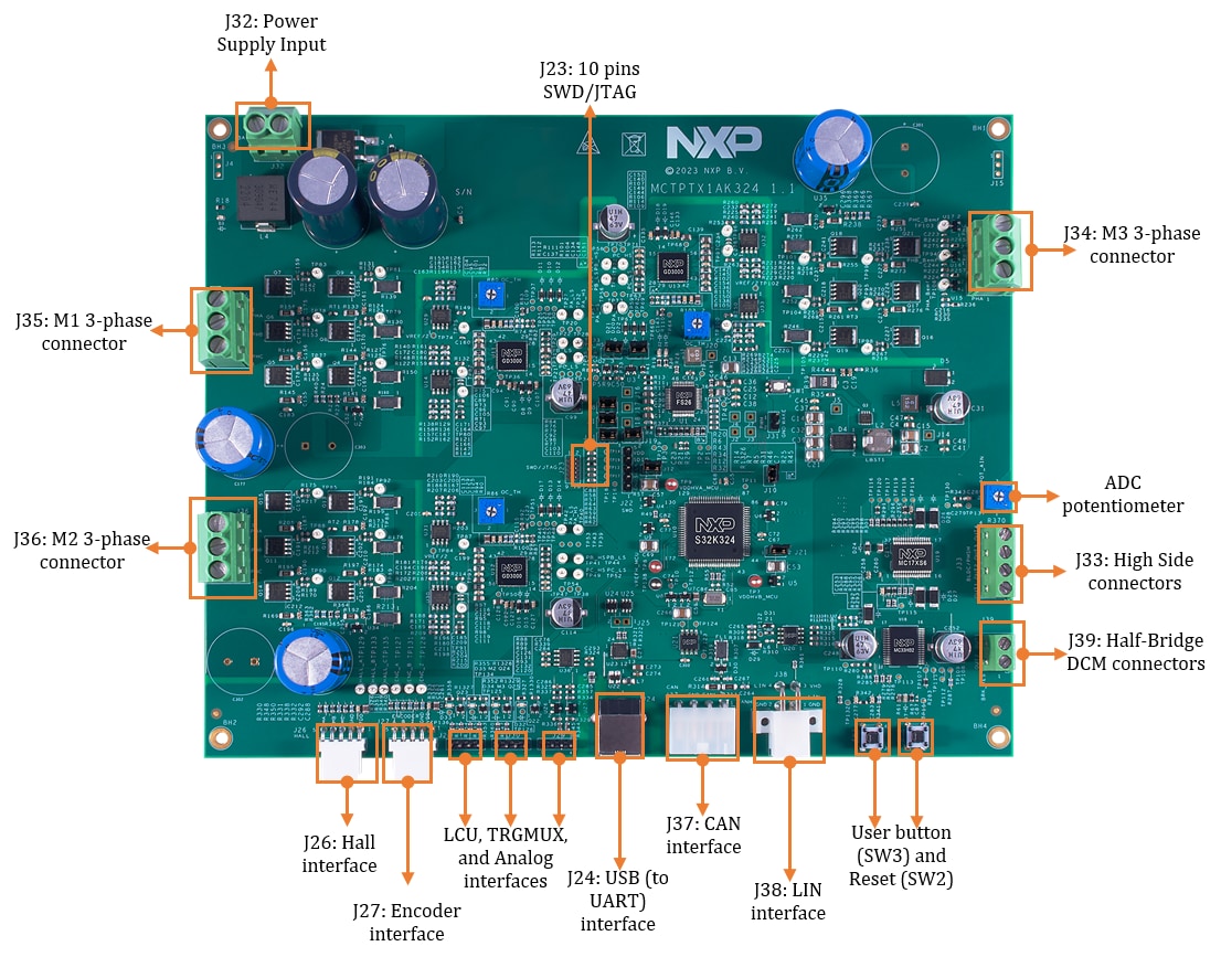
3.3 Connect the Motor
Connect three permanent magnet motors in J34, J35, and J36 connectors. DC motor connected in J39. And if you are
controlling valves, connect them in J33.
3.4 Plug in the Power Supply
Attach the 12 V power cable for powering your MCTPTX1AK324 development board, the LED D2, D3, and D6 would turn on green.
3.5 Plug In the Debugger
Attach your Arm-Cortex compatible JTAG/SWD debugger to the connector J22 or J23.
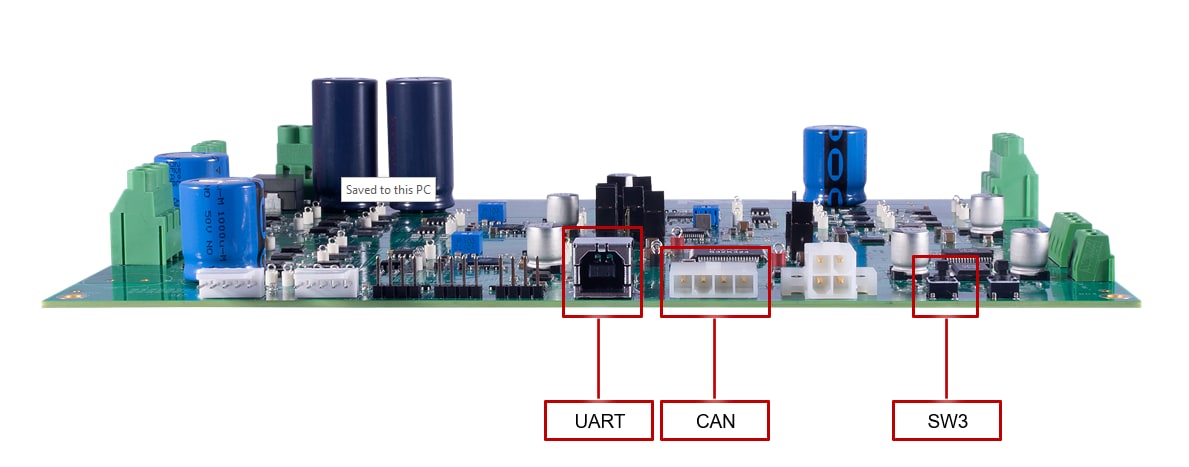
3.6 Plug In the Serial Interface
Attach J24 USB to serial interface for FreeMASTER communication. Please plug it in if you want to control and monitor motors though FreeMASTER.
3.7 Plug In the CAN Interface
Connector J37 is for CAN communication. Please plug it in if you want to control and monitor motors through CAN bus.
Run the MCTPTX1AK324 Reference Design Board
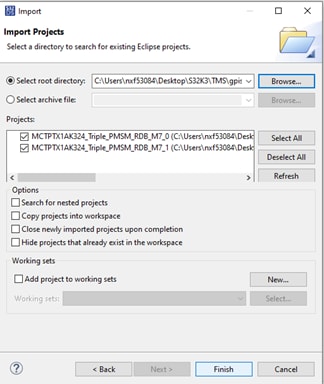
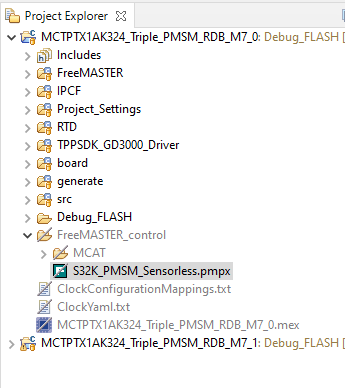
Import the Demo Project Using Your IDE
Import the installed application software project into the S32 Design Studio.
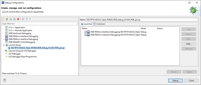
Load Code Into the S32K324 MCU
In the S32 Design Studio menu click Run > Debug Configuration and select the predefined debug configuration and click on Debug to start loading built code into MCU.
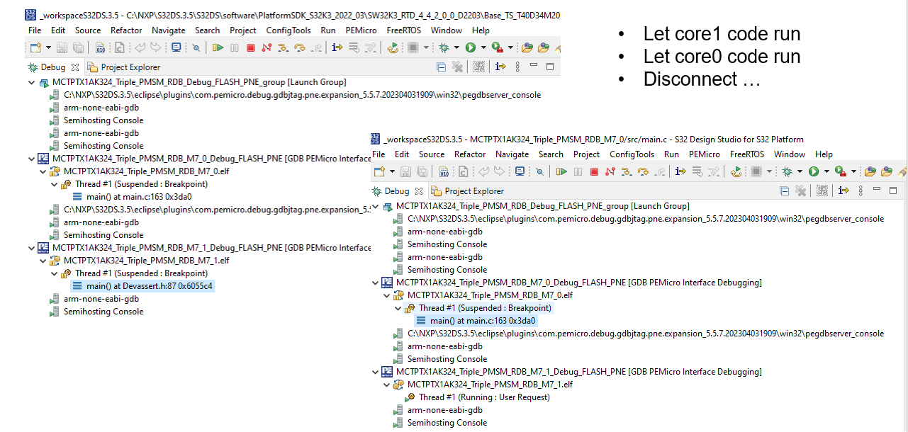
Let the Code Run on the MCU
After the code was loaded into MCU, the S32DS will switch into debug perspective where you may let the code run by clicking on Resume (or press F8) and use Disconnect to avoid interference between the S32DS IDE debugger and the FreeMASTER tool.
Run the Motors
There are 3 ways to run the motors, FreeMASTER over UART, CAN and button SW3.
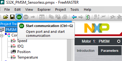
Approach 1. Run the Motors With FreeMASTER
Open S32K_PMSM_Sensorless.pmpx file from MCTPTX1AK324_Triple_PMSM_RDB_M7_0 \FreeMASTER_control folder.
Click the green GO! button in the FreeMASTER toolbar (or press <CTRL> + <G>) to enable the communication
Successful communication is signalized in the status bar at very bottom as:
RS232 UART Communication;COMn; speed = 115200
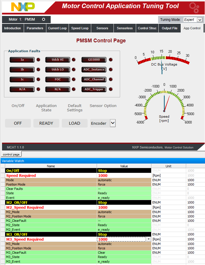
In FreeMASTER, go to Control page tab, set required motor rpms and turn on the motor drive.
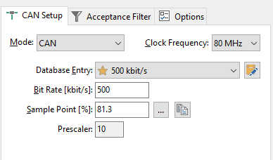
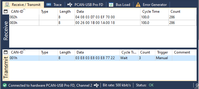
Approach 2. Run the Motors With CAN bus
Use a CAN Interface to connect the board.
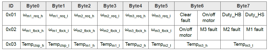
Transmit a CAN standard frame using 0x01 ID to start motors. And the motors state will be feedbacked by ID 0x02 and 0x03 frames.
CAN frame definition table.
Design Resources
Board Documents
Chip Documents
- Motor Control Solutions Based on S32K3 MCUs Brochure
- S32K3 Arm Cortex-M7-Based Automotive MCUs Brochure
- S32K3xxDS: S32K3xx MCU Family - Data Sheet
- FS26, Safety System Basis Chip with Low Power for ASIL D /ASIL B - Product Brief
- S32K3xx MCU Family - Reference Manual
- Mask Set Errata for Mask 0P55A/1P55A - Errata
- MC33GD3000, Three Phase Field Effect Transistor Pre-driver - Data Sheet
- MC33HB2001, 10 A H-Bridge, programmable brushed DC motor driver - Data Sheet
- MC12XS6D1, 17 mOhm and 7.0 mOhm High-side Switches - Data Sheet
Software
- MCTPTX1AK324 Development Kit Application Software
- MCTPTX1AK324 Evaluation Board Software User Manual
- S32K3 Standard Software Package
- S32K3 Reference Software Package
- S32 Design Studio IDE
- Real-Time Drivers (RTD)
- S32K Power Estimation Tool (PET)
- Model-Based Design Toolbox (MBDT)
- Structural Core Self-Test (SCST) Library
- FreeMASTER Run-Time Debugging Tool
- Inter-Platform Communication Framework (IPCF)
- Automotive Math and Motor Control Library (AMMCLib)
- S32 Safety Software Framework (SAF) and Safety Peripheral Drivers (SPD)
- Automotive Software Package Manager
Support
Trainings
Forums
Connect with other engineers and get expert advice on designing with the MCTPTX1AK324 using our community sites.
On this page
- 2.1
Download the Development Kit - Application Software
- 2.2
Get the Integrated Development Environment (IDE)
- 2.3
Get the Development Packages
- 2.4
Get Automotive Math and Motor Control Library (AMMCLib)
- 2.5
Get the Run-Time Debugging Tool
- 3.1
Check the Default Jumper Positions In the MCTPTX1AK324 Evaluation Board
- 3.2
GD3000 Overcurrent Compare Setting
- 3.3
Connect the Motor
- 3.4
Plug in the Power Supply
- 3.5
Plug In the Debugger
- 3.6
Plug In the Serial Interface
- 3.7
Plug In the CAN Interface