
Product Longevity
Participating products are available for a minimum of 10 years. Designated participating products developed for the automotive, telecom and medical segments are available for a minimum of 15 years.
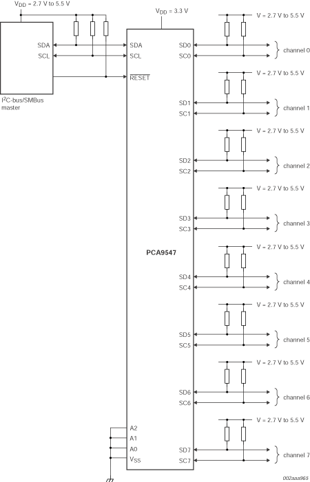
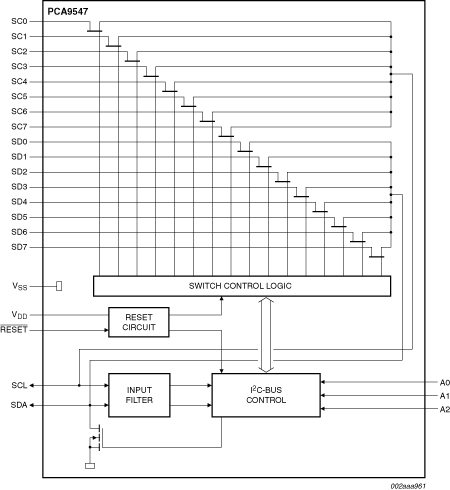
The PCA9547 is an octal bidirectional translating multiplexer controlled by the I²C-bus. The SCL/SDA upstream pair fans out to eight downstream pairs, or channels. Only one SCx/SDx channel can be selected at a time, determined by the contents of the programmable control register. The device powers up with Channel 0 connected, allowing immediate communication between the controller and downstream devices on that channel.
An active LOW reset input allows the PCA9547 to recover from a situation where one of the downstream I²C-buses is stuck in a LOW state. Pulling the RESET pin LOW resets the I²C-bus state machine causing all the channels to be deselected, except Channel 0 so that the controller can regain control of the bus.
The pass gates of the multiplexers are constructed such that the VDD pin can be used to limit the maximum high voltage which will be passed by the PCA9547. This allows the use of different bus voltages on each pair, so that 1.8 V, 2.5 V, or 3.3 V parts can communicate with 5 V parts without any additional protection. External pull-up resistors pull the bus up to the desired voltage level for each channel. All I/O pins are 5 V tolerant.
Choose a diagram:
Participating products are available for a minimum of 10 years. Designated participating products developed for the automotive, telecom and medical segments are available for a minimum of 15 years.
|
|
|
|
|
|
|
|---|---|---|---|---|---|
|
|
|
|
|
|
|
|
|
|
|
|
|
|
|
|
|
|
|
|
|
|
|
|
|
|
|
|
|
|
|
|
|
|
|
|
|
|
|
|
|
|
|
|
|
|
|
|
|
|
|
|
|
|
|
|
|
|
|
|
|
|
|
|
|
|
|
|
|
|
Quick reference to our documentation types
1-10 of 12 documents
Compact List
3 design files
Receive the full breakdown. See the product footprint and more in the eCad file.