Design Files
Quick reference to our
design files types.
1 design file
Receive the full breakdown. See the product footprint and more in the eCad file.
-
Models
A3I25X050N S-Parameters
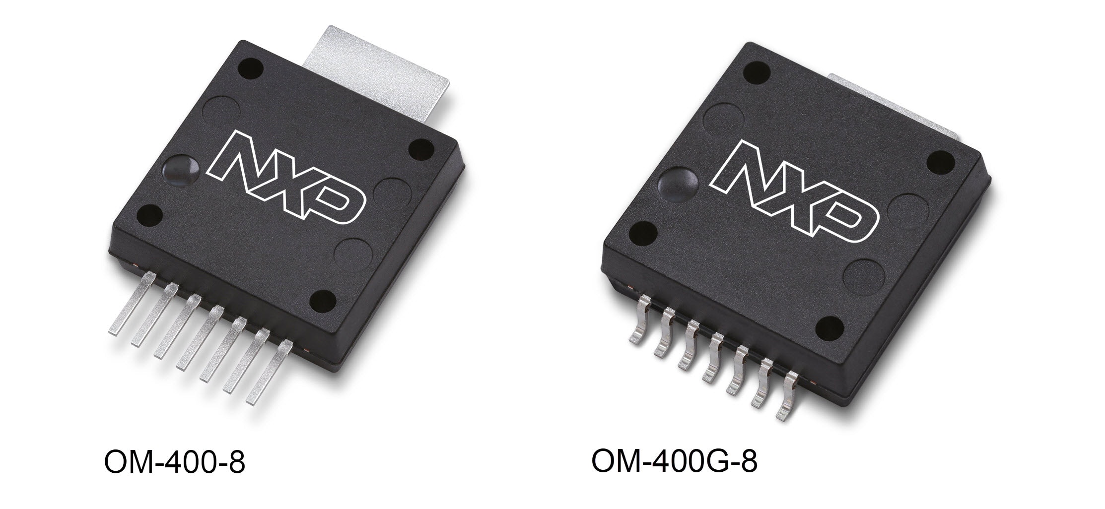
The A3I25X050N integrated Doherty circuit is designed with on-chip matching that makes it usable from 2300 to 2700 MHz. This multi-stage structure is rated for 20 to 32 V operation and covers all typical cellular base station modulation formats.

| Frequency | Gps (dB) |
PAE (%) |
ACPR (dBc) |
| 2496 MHz | 28.5 | 38.2 | –35.3 |
| 2590 MHz | 28.8 | 39.0 | –35.5 |
| 2690 MHz | 28.5 | 37.0 | –35.9 |
| Frequency | Gps (dB) |
PAE (%) |
ACPR (dBc) |
| 2496 MHz | 27.8 | 44.4 | –32.1 |
| 2590 MHz | 28.0 | 44.8 | –31.9 |
| 2690 MHz | 28.0 | 43.7 | –30.8 |
| Frequency | Gps (dB) |
PAE (%) |
ACPR (dBc) |
| 2300 MHz | 29.2 | 44.5 | –30.6 |
| 2350 MHz | 28.6 | 45.0 | –31.5 |
| 2400 MHz | 28.3 | 44.7 | –33.0 |
|
|
|
|
|
|
|
|---|---|---|---|---|---|
|
|
|
|
|
|
|
|
|
|
|
|
|
|
|
|
|
|
|
|
|
|
|
|
|
|
|
|
|
|
|
|
|
|
|
|
|
|
|
|
|
|
|
|
|
|
|
|
|
|
|
|
|
|
|
|
|
|
|
|
|
|
|
|
|
|
|
|
|
|
Quick reference to our documentation types.
4 documents
Please wait while your secure files are loading.
1 design file
Receive the full breakdown. See the product footprint and more in the eCad file.
Please wait while your secure files are loading.