At the end of my
previous post – Top Clip
, I mentioned we would be moving on to the subject of top-side cooling next.
While we are definitely going there, I’d like to cover one other topic
first, which will ultimately form part of the overall top-side cooling story.
A question regularly asked by our customers is “Can I determine the
junction temperature (Tj) of my MOSFET from its case temperature
(Tcase)?”. This is a perfectly reasonable thing to ask
because we certainly want to know whether our MOSFETs are running at a safe
temperature in-circuit, but at the same time determining Tj
in-circuit can be extremely difficult. On the other hand, Tcase can
often be determined quite easily by using a thermocouple or (preferably) a
thermal camera. So, can we infer Tj from Tcase? This
question has arisen so often that we recently performed a series of
experiments to determine if such a correlation between Tj and Tcase
does indeed exist.
To carry out this experiment we need a method of applying a constant, known
power dissipation (PD) to a device whilst simultaneously monitoring
its steady-state Tj. Fortunately such a method exists and is
thoroughly documented in
JEDEC
standard JESD51-1. This describes how a MOSFET body diode can be used
simultaneously as both a heating element and calibrated temperature sensor.
JESD51-2 describes a standardized test environment so we can use that too, and
off-the-shelf test equipment for carrying out thermal analysis is available
from various manufacturers including
Analysis Tech
and
Mentor Graphics.
Most of the queries we received on this subject relate to
LFPAK56
devices, so we’ll focus on those in this experiment, and we’ll
carry out the tests for three different PCB copper areas and a range of power
dissipations. Add a thermal camera to measure Tcase on the top of
the device and we’re ready to go!
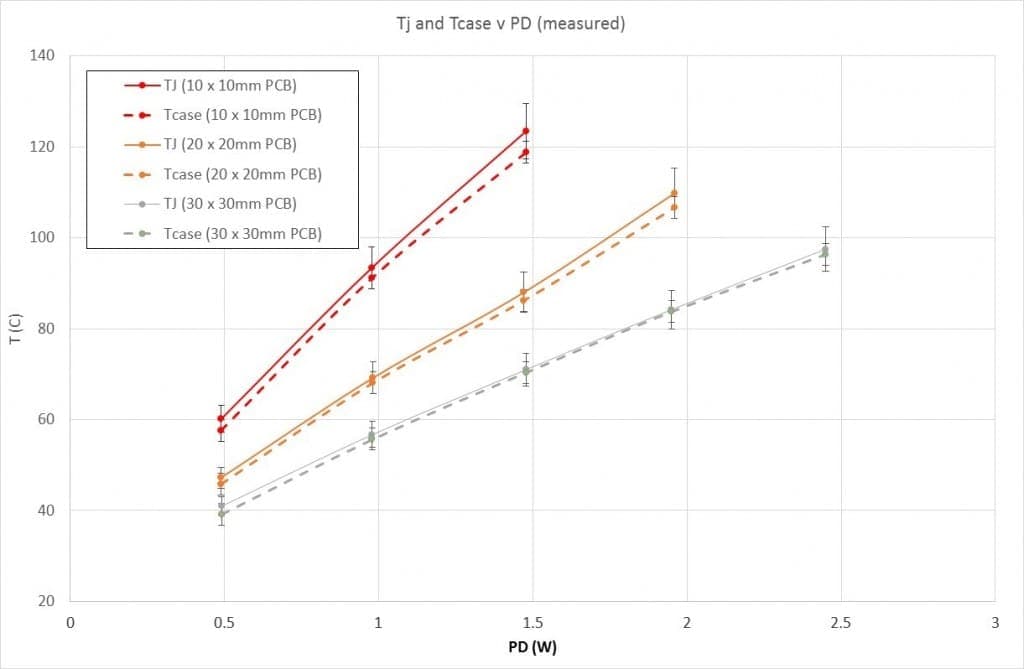
In the graph below you can see the results.

Figure 1 Measured Tj and Tcase v PD for an
LFPAK56 device on various PCBs
The graph of Figure 1 demonstrates that Tj and Tcase are
indeed very close in most cases – with the worst-case difference
being around 4% for the 10×10 mm PCB. Of course, as these are real
measurements we also have to consider that the measurement methods will have
their own accuracy limits, and these are included in the graph as vertical
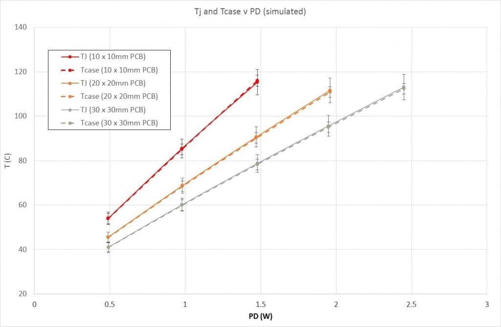
error bars. If I carry out thermal simulations of similar device and PCB
setups then the Tj and Tcase results are even closer, as
can be seen in Figure 2. This time, the temperatures are almost identical.

Figure 2 Simulated Tj and Tcase v PD for an LFPAK56 device on various
PCBs
This is a very useful result as it would tend to suggest that, for the LFPAK56
package at least, we can consider Tj and Tcase to be
almost the same with a reasonable degree of accuracy. It’s also
probably fair to say that this is another example of a non-intuitive result!
In my next post I’ll return to this subject and consider
why Tj and Tcase are so similar. In the
meantime, the interested reader might like to ponder for themselves reasons
why Tj @ Tcase (hint: and it doesn’t really have
anything to do with thermal resistances).


