Getting Started with the DEVKIT-MOTORGD
Contents of this document
-
Build the Setup
-
Get Software
-
Program the Base Board
Sign in to save your progress. Don't have an account? Create one.
Purchase your Motor Control Shield for DEVKIT
1. Build the Setup
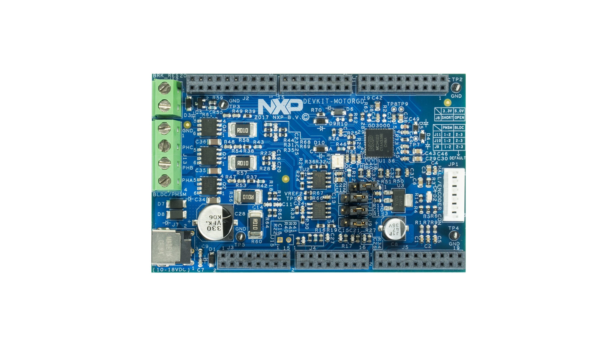
1.1 Get Started with DEVKIT-MOTORGD Motor Control Shield
The DEVKIT-MOTORGD is Arduino UNO compatible, as with its compatible base boards. The inner rows conform to the Arduino standard while the outer rows accommodate propriety NXP function pins. Let's take your DEVKIT-MOTORGD for a test drive! Follow the detailed actions listed below.
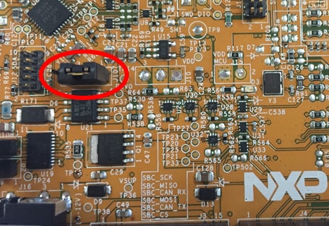
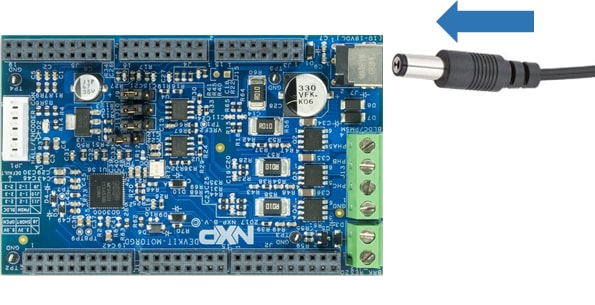
1.2 Configure Base Board to be Powered Externally
Driving a motor requires a higher input voltage than what a USB is capable of supplying. The base board will therefore need to be configured to power from an external power supply. On S32K144EVB-Q100, connect J107.1 to J107.2, like so.
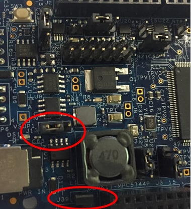
You can do the same thing on DEVKIT-MPC5744P. Connect J13.1 to J13.2 and also apply a jumper to J39.
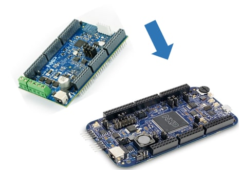
1.3 Plug in DEVKIT-MOTORGD
Plug in DEVKIT-MOTORGD Arduino-style into the base board. Make sure the pins match up.
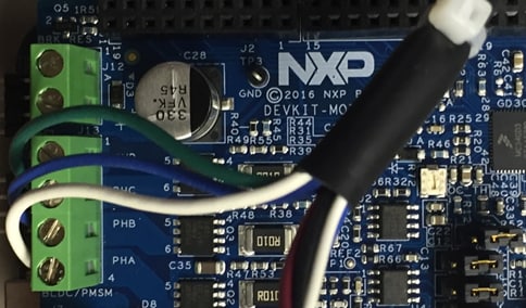
1.4 Connect the Motor
Connect a 3-phase motor to DEVKIT-MOTORGD at J13. DEVKIT-MOTORGD supports BLDC (sensored and sensorless) and PMSM. Connect the phase terminals to what suits your application best. NXP sample code uses the Linux 45ZWN24-40 BLDC motor and connects Phase A to White, Phase B to Blue, and Phase C to Green.
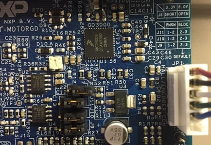
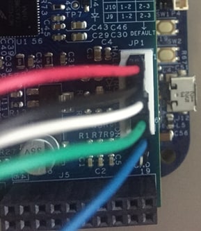
If your motor has a hall encoder or position sensor, connect it to the terminal JP1 like so.
1.5 Connect the Motor (Alternative)
An alternative motor is the Nanotec DB41M024030-A . The motor ships with its wires like so:
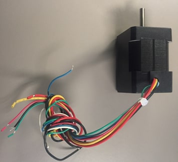
The three thick wires are the phases (red, yellow, black) and the five slender wires are the hall sensor (red, black, white, green, blue). To run NXP sample code connect Phase A to Yellow, Phase B to Red, and Phase C to Black.
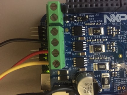
The Hall interface wires follow the same color coding as the Linux 45ZWN24-40. Connect the wires going down from the JP1 label as follows: red, black, white, green, blue, no wire (leave JP1.6 unconnected).
2. Get Software
2.1 Jump Start Your Design
Download Quick Start Guide and sample software to kickstart your design.
Get DEVKIT-MOTORGD Quick Start Guide
The software below is for evaluation purposes only. Its purpose is to show how DEVKIT-MOTORGD supports easy prototyping. The setup steps described on this "Getting Started" page describe general steps that all projects using DEVKIT-MOTORGD would need to go through. Click on the button below to access the full setup instructions for NXP's sample software.
How to setup NXP software example
2.2 Install Your Toolchain
NXP offers a complimentary toolchain called S32 Design Studio (S32DS). The S32 Design Studio is an Eclipse-based IDE that offers comprehensive software writing and debugging capabilities. It supports multiple debuggers including GDB and Lauterbach.
NXP also offers the Model-Based Design Toolbox, which is a Simulink-based tool that lets you graphically build your application before generating code.
Get Model-Based Design Toolbox
Click on the buttons below for more information on the toolbox's capabilities with each platform.
Get S32K MBDT Information Get MPC5744P MBDT Information
2.3 Download FreeMASTER
FreeMASTER is a free-to-use debug monitor from NXP. Supports non-intrusive monitoring of variables on a running system. You can display multiple variables changing over time on an oscilloscope-like display or view the data in text form.
3. Program the Base Board
Learn how to create a new project in S32 Design Studio IDE for Power Architecture and the basics to create your own code by running an easy example code.
3.1 Get More Training
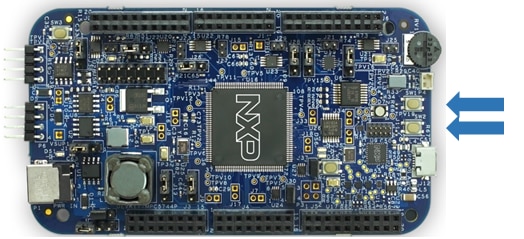
Both S32K144EVB-Q100 and DEVKIT-MPC5744P support OpenSDA. Plug in USB. Program a motor control program using S32 Design Studio or debug interface of your choice.
S32K144EVB-Q100 DEVKIT-MPC5744P
3.2 Run It
Power-cycle the setup and watch the motor spin.
If you installed NXP sample software following the supplemental tutorial in the previous step, the controls are as follows:
- Press
SW1to speed up - Press
SW2to slow down/reverse
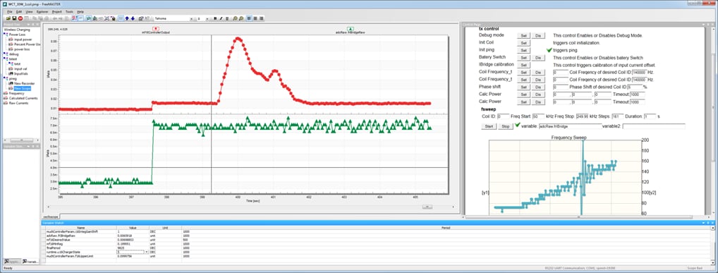
3.3 Control with FreeMASTER
Open the FreeMASTER projects attached with the NXP software. Setup board connection to FreeMASTER and let it run.
Tera Term Tutorial
Tera Term Tutorial
Tera Term is a very popular open source terminal emulation application. This program can be used to display information sent from your NXP development platform's virtual serial port.
- Download Tera Term from SourceForge. After the download, run the installer and then return to this webpage to continue
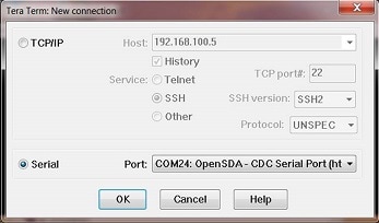
- Launch Tera Term. The first time it launches, it will show you the following dialog. Select the Serial option. Assuming your board is plugged in, there should be a COM port automatically populated in the list
- Configure the serial port settings (using the COM port number identified earlier) to 19,200 baud rate, 8 data bits, no parity and 1 stop bit. To do this, go to Setup → Serial Port and change the settings
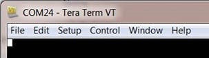
- Verify that the connection is open. If connected, Tera Term will show something like below in its title bar
- You're ready to go
PuTTY Tutorial
PuTTY Tutorial
PuTTY is a popular terminal emulation application. This program can be used to display information sent from your NXP development platform's virtual serial port.
- Download PuTTY using the button below. After the download, run the installer and then return to this webpage to continue
- Launch PuTTY by either double clicking on the *.exe file you downloaded or from the Start menu, depending on the type of download you selected
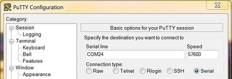
- Configure in the window that launches, select the Serial radio button and enter the COM port number that you determined earlier. Also, enter the baud rate, in this case 19,200
- Click open to open the serial connection. Assuming the board is connected and you entered the correct COM port, the terminal window will open. If the configuration is not correct, PuTTY will alert you
- You're ready to go
Design Resources
Support
Trainings
Enjoy these video tutorials on how to use DEVKIT-MOTORGD with S32K144EVB-Q100 and DEVKIT-MPC5744P.
Forums
Connect with other engineers and get expert advice on designing with DEVKIT-MOTORGD on our community site.