Getting Started with NAFE33352-UIOM Evaluation Board
Contents of this document
-
Out of the Box
-
Get Hardware
-
Plug It In
-
Build and Load
-
Quick Steps to Evaluate
Sign in to save your progress. Don't have an account? Create one.
Purchase your NAFE33352-UIOM Universal AIO AFE Arduino® Shield Evaluation Board
1. Out of the Box
The NXP analog product development boards are easy-to-use platforms for evaluating NXP products. These boards support a range of analog, mixed-signal and power solutions. They incorporate monolithic integrated circuits (ICs) and system-in-package (SiP) devices based on high-volume technologies. NXP solutions enable improved performance, a small form factor, reduced component counts and lower overall system cost in powering state-of-the-art designs.
This page will guide you through set up and operation of the NAFE33352-UIOM evaluation board.
1.1 Kit Contents and Packing List
The kit contents include:
- Assembled and tested NAFE33352-UIOM evaluation board in an antistatic bag
- USB 2.0 cable
- Spare jumpers
1.2 Additional Hardware
In addition to the kit contents, you will also need the following hardware:
- FRDM‑MCXN947 evaluation board
1.3 Minimum System Requirements
You will need a Windows PC for the evaluation board process. It is recommended that your workstation be equipped with the following:
- PC with Windows 7, 8 or 10 operating system
- One USB port (2.0 compatible)
- USB cable for power and data connection between PC and evaluation kit (EVK) board
1.4 Software for GUI-Based Evaluation
In addition to setting up your PC workstation, you will also need to install software. The related software is available on the evaluation board's information page.
2. Get Hardware
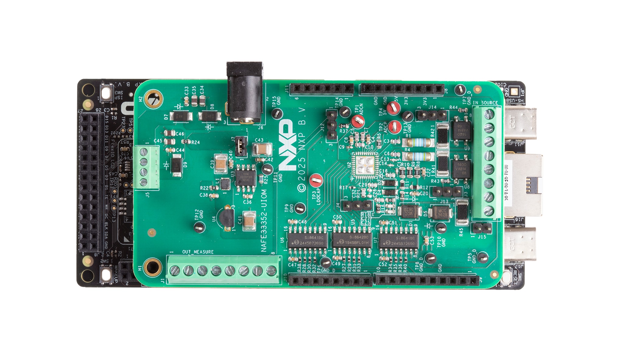
2.1 Board Features
The table below describes the board features of NAFE33352-UIOM.
| Device | Description | Location |
|---|---|---|
| Universal analog input/output (AIO) software (SW)-configurable AIO-analog front end (AFE) | NAFE33352 | U2 |
| Single-pole single-throw (SPST) analog switches | Switches | U8 and U9 |
| Linear drop-out (LDO) regulator | LDO | U4 |
| High-voltage, charge pump DC-DC converter | Charge pump | U3 |
| Quad-channel digital isolators | Digital isolator | U6, U5 and U7 |
2.2 Board Description
NXP’s NAFE33352-UIOM platform is a deployment-ready solution that helps engineers validate analog accuracy and diagnostics before scaling to production. This compact board (90 mm x 50 mm) integrates seamlessly with NXP MCX-N microcontroller (MCU) boards via Arduino connectors, offering plug-and-play flexibility for rapid prototyping.
Key features include:
- Universal analog inputs for voltage, current, resistance temperature detector (RTD) and thermocouple sensing
- Analog output up to ±12.5 V and ±25 mA for precise actuation
- Built-in calibration and diagnostics to reduce scale-up risk
- NAFE graphical user interface (GUI) and driver packs for fast configuration and development
NAFE33352 AFE integrates a high-resolution sigma-delta analog-to-digital converter (ADC) for precise sensing and digital-to-analog converter (DAC) for accurate actuation. NAFE33352 enables seamless interaction between sensors and actuators in closed-loop systems. This integration reduces the need for multiple discrete components, saving board space and simplifying design. NAFE33352 offers premium performance without compromise, helping engineers accelerate development and optimize reliability.
NAFE33352 offers superior accuracy and a highly integrated architecture, supporting both analog input and analog output in a single device. A GUI for this NAFE33352-UIOM platform allows the user to easily navigate the different functions of the driver. The IC communicates to the host via the industry-standard serial peripheral interface (SPI)-bus port. The evaluation software runs on Microsoft Windows 7, 8 and 10 PC platforms.
2.3 Board Components
Figure 1 below shows the key components on the NAFE33352-UIOM evaluation board.

3. Plug It In
3.1 NAFE33352-UIOM Evaluation with NAFE33352-UIOM GUI
This section provides NAFE33352-UIOM installation requisites and instructions to install the same.
3.2 Installing the Software for GUI Operation
Download and install the NAFE33352-UIOM GUI software.
3.3 NAFE33352-UIOM Applications
The GUI provides NAFE33352-UIOM example codes and a detailed overview about hardware and software steps to evaluate NAFE33352-UIOM.
Follow the steps given below to install the NAFE33352-UIOM GUI.
- Running the installer application begins the process and click Next
- Select the installation location by clicking browse and select the user for NAFE33352-UIOM by selecting Everyone/Just me and click Next
- After confirming the message that now appears on the dialog box and click Next to begin the installation
- After the installation is complete, a dialog box displays the Installation Complete message and Click Close to close the dialog box
- After the installation is complete, check the NAFE33352-UIOM GUI guide to configure NAFE33352 and run different applications (For running on-board RTD applications, a few hardware modifications are needed)
- Remove resistor R39 and cut the trace connected to pin 13 of U7
For full installation instructions, including images of the steps, refer to chapter 7 of NAFE33352-UIOM Analog Sensing and Control Platform User Manual
4. Build and Load
4.1 Build and Load
The NAFE33352 Arduino UIOM kit includes the NAFE33352 evaluation board, an FRDM-MCXN 947 and a USB cable.
4.2 Configuring the Hardware
To set up the hardware, perform the below steps:
- Firmly connect the NAFE33352 Arduino UIOM board to the FRDM MCXN-947 evaluation board using the Arduino connectors
- To connect both boards, slide J8, J9, J10 and J11 male connectors at the bottom side of the NAFE33352 (AFE) evaluation board into the appropriate female connectors on the FRDM MCX-N 947 evaluation board
- Connect an adapter supply in the +7 V to +15 V range on J6 (an approximately 0.4 V accounts for the voltage drop across the Schottky diode for reverse polarity protection and voltage drop across the 5 Ω resistor because of the supply current flowing into the pin of the device)
- Use a USB to uUSB to connect the PC (USB) to the FRDM MCXN-947
For full installation instructions, including images of the steps, refer to chapter 6.4 of NAFE33352-UIOM Analog Sensing and Control Platform User Manual.
5. Quick Steps to Evaluate
5.1 Quick Steps to Evaluate Universal Analog Sensing and Control Platform

- Connect the provided 15 V power adapter to the J6 DC power jack on the NAFE33352-UIOM board
- Connect the cable (MCU-Link USB) provided to the FRDM-MCXN947 board/kit
- Install the NAFE33352-UIOM GUI and connect to the appropriate COM port
- In the GUI, select voltage analog digital (VADD)/voltage common mode (VCM) in the INSEL dropdown menu and click Write All
- Click Single Channel Single Reading (SCSR) in the ADC Single Channel Mode section
Design Resources
Board Information
Additional References
In addition to the NAFE33352-UIOM page, you will also find valuable information on the FRDM-MCXN947 board page.