Getting Started with the FRDM-XS2410EVB
Contents of this document
-
Out of the Box
-
Plug It In
-
Configure Hardware
-
Get Software
Sign in to save your progress. Don't have an account? Create one.
Purchase your XS2410 FRDM Evaluation Board
1. Out of the Box
The NXP analog product development boards provide an easy-to-use platform for evaluating NXP products. The boards support a range of analog, mixed-signal and power solutions. They incorporate monolithic integrated circuits and system-in-package devices that use proven high-volume technology. NXP products offer longer battery life, a smaller form factor, reduced component counts, lower cost and improved performance in powering state-of-the-art systems.
This page will guide you through the process of setting up and using the FRDM- XS2410EVB evaluation board.
1.1 Kit Contents/Packing List
The FRDM-XS2410EVB contents include:
- Assembled and tested FRDM-XS2410EVB board in an anti-static bag
- Power connector 2x1 for power supply
- Power connector 5x1 for outputs and ground
- Jumpers mounted on board
- Quick start guide
1.2 Additional Hardware
In addition to the kit contents, the following hardware is necessary or beneficial when working with this kit.
- Power supply with a range of 0 V to 60 V and a DC current capability up to 10 A
1.3 Windows PC Workstation
This evaluation board requires a Windows PC workstation. Meeting these minimum specifications should produce great results when working with this kit.
- USB-enabled computer with Windows 7 or Windows 10
2. Plug It In
2.1 Board Features
- VBAT power supply connectors 0 V to 60 V (Jack and Phoenix)
- Four high-side outputs 100 mΩ up to 2.5 A per channel at room temperature
- 5.0 V supply regulator for VDD pin
- Manual switches for direct input control in safe mode
- Limp button to force safe mode externally
- LEDs to witness output state, VDD supply or warning and fault in FAULTB IRQ pin
- Four headers to connect on compatible hardware (FRDM-KL25Z, S32K144 or Arduino R3)
- Jumpers to enable LEDs, freewheeling diodes when driving inductive load, VDD connection or MCU supply
2.2 Board Description
The main purpose of this kit is to program the board and evaluate all the different features of the MC33XS2410 along with a power supply and real loads.
The FRDM-XS2410EVB provides flexibility to interact with all the features of the device and perform measurements on the main part of the application. With compatible pinouts, the FRDM-XS2410EVB can be interfaced to either FRDM-KL25Z MCU or S32K144EVB FRDM boards.
With the FlexGUI software loaded, the evaluation board allows access to the registers in read and write mode, device configuration and monitoring key diagnostics parameters. Power outputs are accessible through connectors, and some of the signal can also be probed using test points. Some LEDs witness the state of the outputs, such as VDD supply or warning/IRQ faults on FAULTB pin.
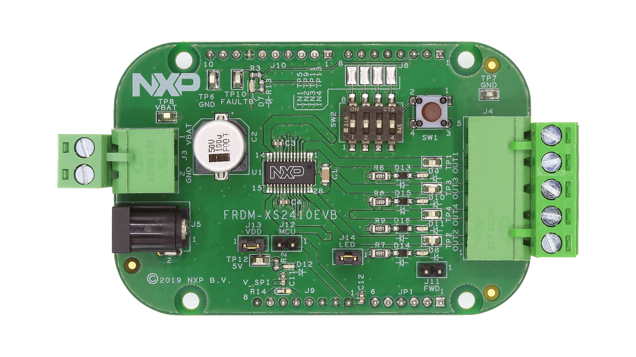
2.3 Board Components
Overview of the FRDM-XS2410EVB evaluation board
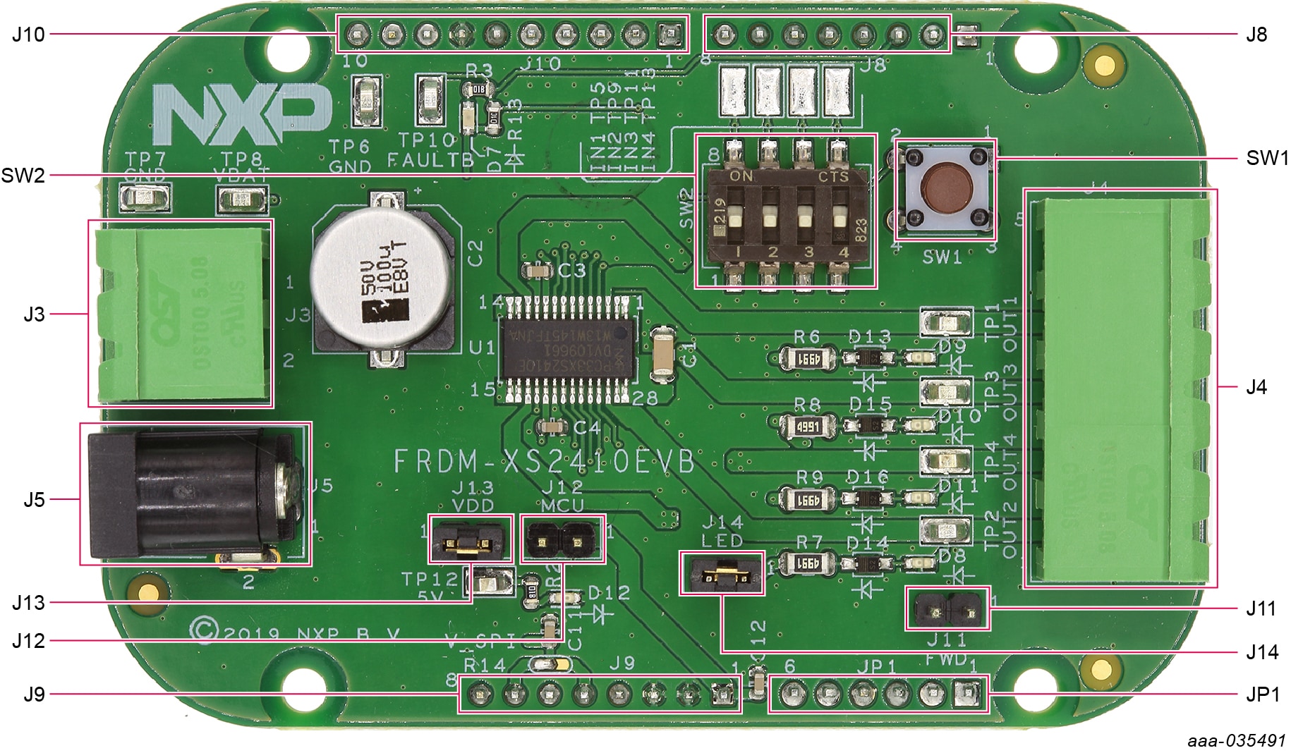
| Output name | Description | Output |
J3 |
VBAT Power (and GND) connector | - |
J4 |
Output 1, Output 2, Output 3, Output 4 (and AGND) connector | - |
J5 |
VBAT Power (and AGND) DC Jack | - |
J8 |
1x8 FRDM board header | - |
J9 |
1x8 FRDM board header | - |
J10 |
1x10 FRDM board header | - |
J11 |
Output freewheeling path jumper | open |
J12 |
5.0 V VDD to MCU jumper | open |
J13 |
5.0 V VDD to Q100 jumper | open |
J14 |
Output LED jumper | short |
JP1 |
1x6 FRDM board header | - |
| SW1 | Push button for LHM (safe mode) | - |
| SW2 | Four ON/OFF switches for direct input 1, input 2, input 3, and input 4 | Off |
3. Configure Hardware
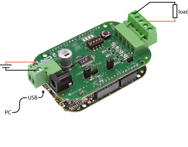
3.1 Configure the Hardware
To configure the hardware, complete the following procedure:
- Connect the FRDM-XS2410EVB to MCU (FRDM-KL25Z or S32K144EVB)
- Set the DC power supply to either
J3orJ5 - Connect the Windows PC USB port to the selected MCU using the provided USB cable
- Set the DC power supply between 3.0 V and 60 V and turn it ON
- Connect loads to
J4connector - Loads can be turned ON using
SW2DIP switches pressingSW1
This board can be used either with FlexGUI software for evaluation or with software drivers for development.
- For FlexGUI software usage, refer to the dedicated user guide for FRDM-XS2410EVB at UM11301
- For XS2410 related software drivers, software examples and documentation, refer to UM11182
4. Get Software
4.1 Prepare Graphical User Interface Operating Environment
All installation details and software flashing on MCU are described UM11301, the dedicated FlexGUI user manual for FRDM-XS2410EVB.
4.2 Start the FlexGUI Application
After the FlexGUI application is started with flexgui-app-des-q100, the FlexGUI launcher displays the supported MCU and communication protocols. After the boards are selected, the GUI starts.
4.3 FlexGUI Workspace and Features
At first launch, the FlexGUI starts in user mode.
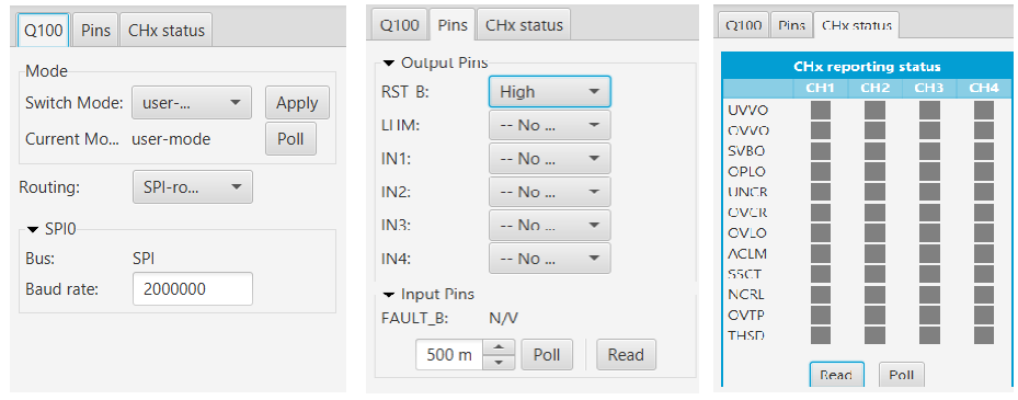
The bottom left area of the GUI shows three tabs:
- Q100: The user can decide to switch to Watchdog Off mode using the Switch mode drop-down list followed by clicking Apply. The SPI frequency may also be changed
- Pins: The Pins tab allows direct control of the various device inputs (IN and LHM) and reading the device output (FAULT_B)
- CHx status: The CHx tab allows reading or polling the different warnings and faults from the four channels
Start embedded application development.
Design Resources
Board Information
Additional References
In addition to our XS2410: Quad 100 mΩ / dual 50 mΩ, 3.0 V to 60 V high-side switch page, you may also want to visit:
Application pages:
- Automotive Advanced Exterior Lighting
- Battery Management System
- Body and Comfort
- MOTION-CONTROL-ROBOTICS: Motion Control and Robotics
Hardware pages:
Software pages: