Getting Started with the FRDMGD3160DSBHB Evaluation Kit
Contents of this document
-
Out of the box
-
Get to know the hardware
-
Install software
-
Configure the hardware
Sign in to save your progress. Don't have an account? Create one.
Purchase your FRDMGD3160DSBHB | GD3160 Half-Bridge Evaluation Kit
1. Out of the box
The NXP analog product development boards provide an easy-to-use platform for evaluating NXP products. The boards support a range of analog, mixed-signal and power solutions. They incorporate monolithic integrated circuits and system-in-package devices that use proven high-volume technology. NXP products offer longer battery life, a smaller form factor, reduced component counts, lower cost and improved performance in powering state-of-the-art systems.
This page will guide you through the process of setting up and using the FRDMGD3160DSBHB board.
1.1 Kit contents/packing list
The FRDMGD3160DSBHB contents include:
- Assembled and tested FRDMGD3160DSBHB board in an anti-static bag
- 3.3 V to 5.0 V translator board (KITGD3160TREVB) connected to a FRDM-KL25Z board
- USB cable, type A male/type mini B male, 3 ft
- Quick Start Guide
1.2 Additional hardware
In addition to the kit contents, the following hardware is necessary or beneficial when working with this reference board.
- Compatible onsemi VE-Trac™ dual DSB IGBT module
- DC link capacitor compatible with the onsemi VE-Trac™ dual DSB IGBT module
- 1.27 mm jumpers for configuration (included with kit)
- 30 μH to 50 μH, high current air core inductor for double pulse testing
- HV power supply with protection shield and hearing protection
- 25 V, 1.0 A DC power supply
- 500 MHz 2.5 GS/s 4-channel oscilloscope
- Rogowski coil, PEM Model CWT Mini HF60R or CTW MiniHF30 (smaller diameter)
- Isolated differential high-voltage probes
- Digital voltmeter
1.3 Windows PC workstation
This reference design requires a Windows PC workstation. Meeting these minimum specifications should produce great results when working with this evaluation board.
- Windows 7 or higher operating system
1.4 Software
Installing software is necessary to work with this reference design. All listed software is available on the information page at http://www.nxp.com/FRDMGD3160DSBHB.
2. Get to know the hardware
2.1 Board features
- Capability to connect to onsemi VE-Trac™ dual DSB IGBT module for half-bridge evaluations
- Negative VEE gate low drive level (−7.5 V DC)
- VCCREG regulated high gate drive level (+15 V DC)
- Jumper configurable for disabling dead time fault protection when short-circuit testing
- Easy access power, ground and signal test points
- Easy to install and use FlexGUI for interfacing via SPI through PC; software includes double pulse and short-circuit testing capability
- DC link bus voltage monitor on low-side driver via AMUXIN and AOUT
- Negative temperature coefficient (NTC) connection and configurable for monitoring module temperature
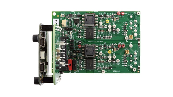
2.2 Board description
The FRDMGD3160DSBHB is a half-bridge evaluation board populated with two GD3160 single channel IGBT or SiC gate drive devices. The board supports connection to an FRDM-KL25Z microcontroller for SPI communication configuration programming and monitoring. The board includes DESAT circuitry for short-circuit detection and implementation of GD3160 shutdown protection capabilities.
The evaluation board is designed to connect to a onsemi VE-Trac™ dual DSB IGBT module for evaluation of the GD3160 performance and capabilities.
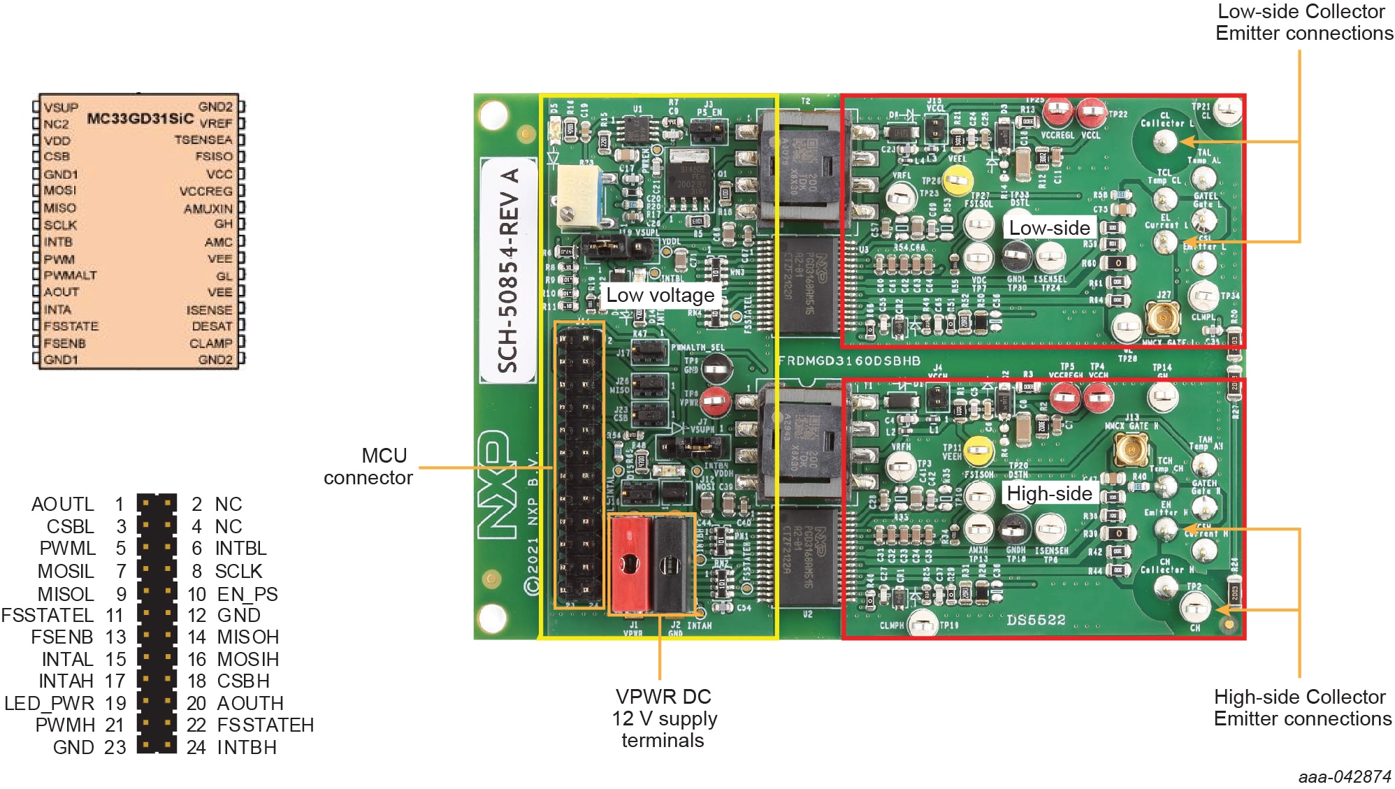
2.3 Board components
Overview of the FRDMGD3160DSBHB board
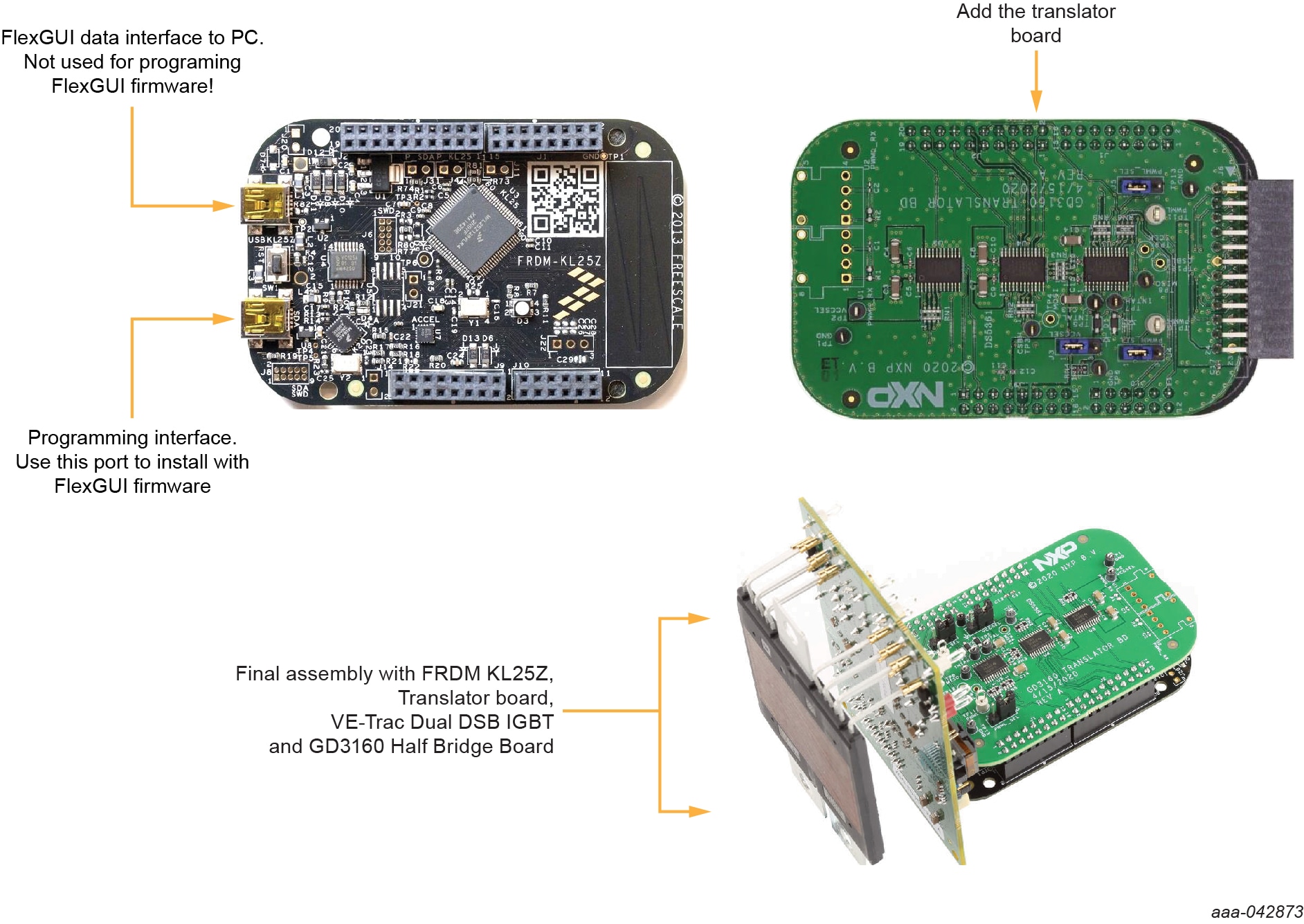
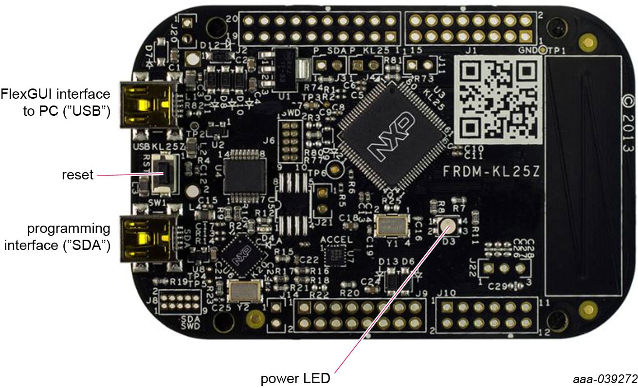
KL25Z Freedom board
The Freedom KL25Z is an ultra low-cost development platform for Kinetis L series MCU built on Arm Cortex-M0+ processor.
3.3 V to 5.0 V translator board
KITGD3160TREVB translator enables level shifting of signals from MCU 3.3 V to 5.0 V SPI communication.
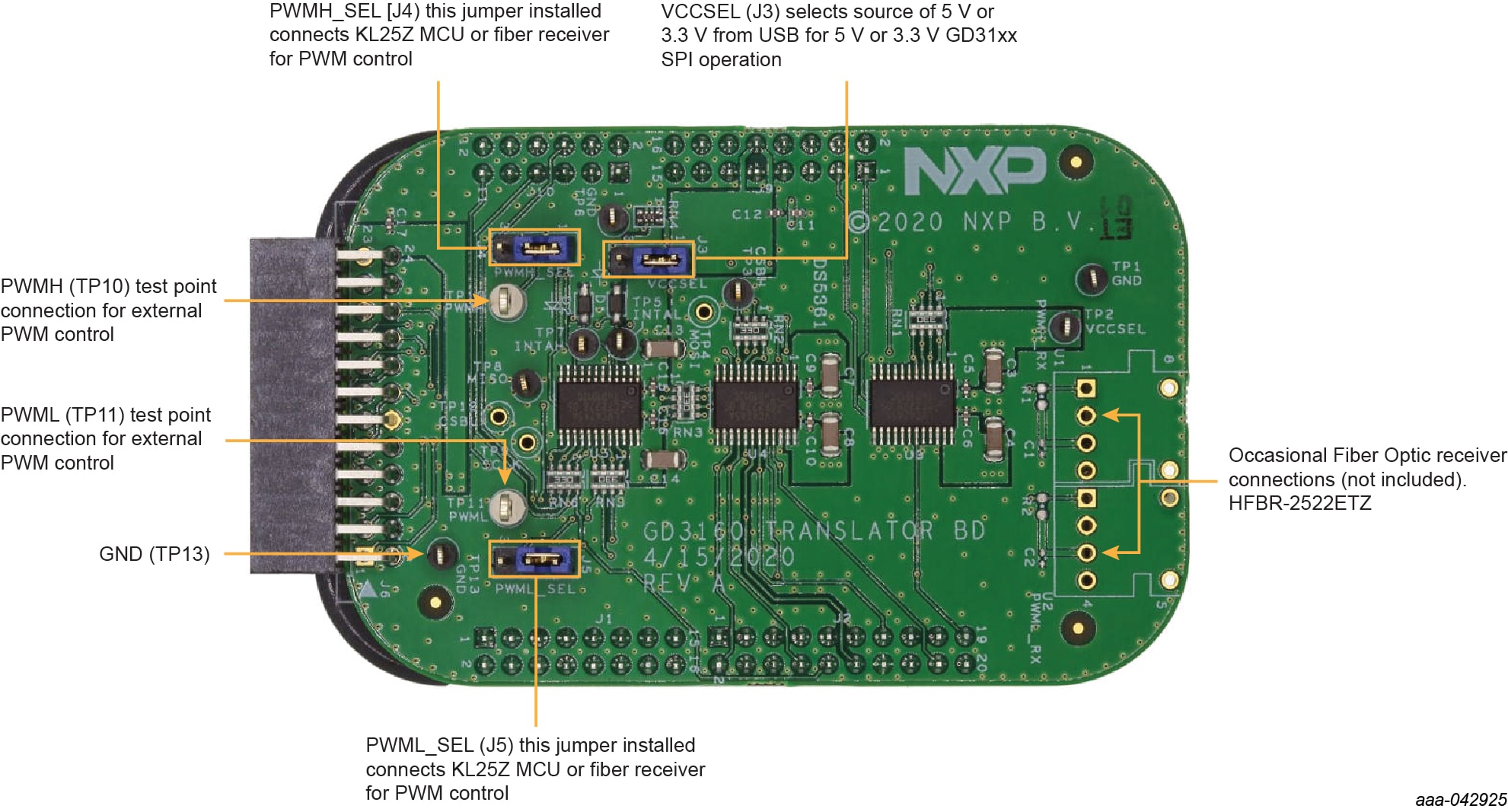
Table 1. Translator board jumper definitions
| Jumper | Position | Function |
|---|---|---|
| VCCSEL (J3) | 1-2 | selects 5.0 V for 5.0 V compatible gate drive |
| 2-3 | selects 3.3 V for 3.3 V compatible gate drive | |
| PWMH_SEL (J4) | 1-2 | selects PWM high-side control from KL25Z MCU |
| 2-3 | selects PWM high-side control from fiber optic receiver inputs | |
| PWML_SEL (J5) | 1-2 | selects PWM low-side control from KL25Z MCU |
| 2-3 | selects PWM low-side control from fiber optic receiver inputs |
3. Install software
Software for FRDMGD3160DSBHB is distributed with the FlexGUI tool (available at nxp.com). Necessary firmware comes pre-installed on the FRDM-KL25Z with the kit.
Even if the user intends to test with other software or PWM, this software should be installed as a backup or as an aid in debugging.
3.1 Install FlexGUI on your computer
The latest version of FlexGUI supports the GD3100 and GD3160. It is designed to run on any Windows 10 or Windows 8 based operating system.
By default, the FlexGUI executable file is installed at C:\flexgui-app-des-gd31xx.exe. Installing the device drivers overwrites any previous FlexGUI installation and replaces it with a current version containing the GD31xx drivers. However, configuration files (.spi) from the previous version remain intact.
To install the software, do the following:
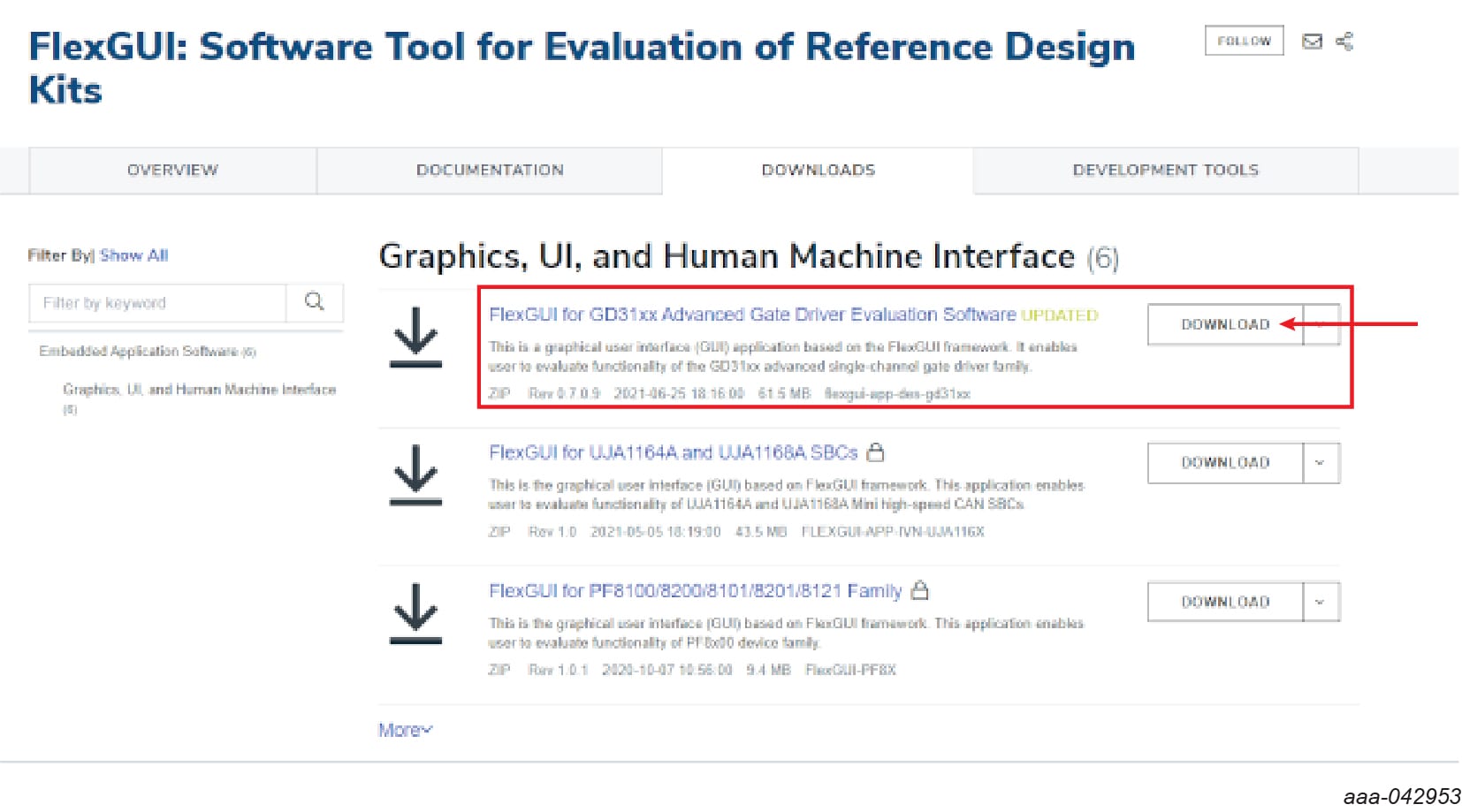
- 1. Go to www.nxp.com/FlexGUI and click on the Download tab.
- 2. When the "Graphics, UI and Human Machine Interface" page appears, click the Download button associated with "FlexGUI for GD31xx Advanced Gate Driver Evaluation Software". When prompted, provide a location where the FlexGUI files are to be downloaded.
- 3. Unzip the downloaded file. Then click on
C:\flexgui-app-des-gd31xx.exeto open the installation wizard.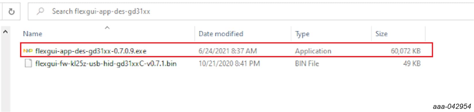
- 4. Follow the installation wizard prompts on the "License Agreement" and the "Select Destination Location" windows.
-
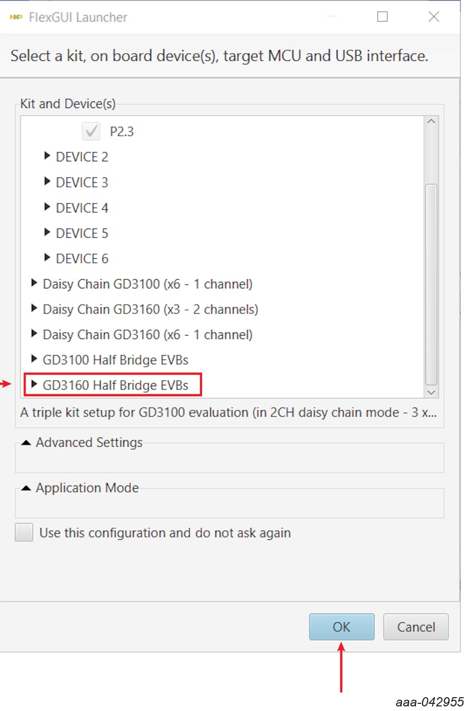
5. At the end of the installation process the FlexGUI automatically opens to the "Kit and Device(s)" selection window. Select
GD3160 Half Bridge EVBs, then click "OK". Do not change any other parameters on this page.
Configure the hardware
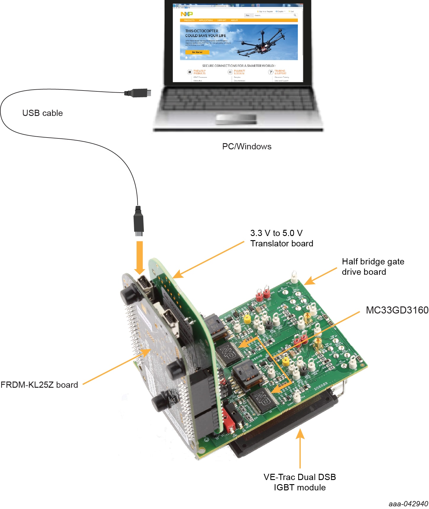
FRDMGD3160DSBHB is connected to compatible onsemi VE-Trac™ dual DSB IGBT module with a DC link capacitor as shown in Figure 4. Double pulse and short-circuit testing can be conducted utilizing Windows-based PC with FlexGUI software.
Suggested equipment needed for test:
- Rogowski coil high-current probe
- High-voltage differential voltage probe
- High sample rate digital oscilloscope with probes
- DC link capacitor compatible with onsemi VE-Trac™ dual DSB IGBT module
- Onsemi VE-Trac™ dual DSB IGBT module
- Windows-based PC
- High-voltage DC power supply for DC link voltage
- Low-voltage DC power supply for VPWR +12 V DC gate drive board low-voltage domain
- Voltmeter for monitoring high-voltage DC link supply
- Load coil for double pulse testing
Design Resources
Board Information
Additional References
In addition to our GD3160: Advanced Single-Channel High-Voltage Isolated Automotive Gate Driver for SiC MOSFETs/IGBTs page, you may also want to visit:
- Gate driver pages: GD3000, GD3100
- Application pages: Hybrid and electric vehicle powertrain, 3-phase high voltage motor control
Get Help
Forums
Connect with other engineers and get expert advice on designing with the S32K3X4EVB-Q257 Evaluation Board using our community sites.