Getting Started with the RDGD3162MITEVM
Contents of this document
-
Out of the Box
-
Get Hardware
-
Install Software
-
Configure Hardware
Sign in to save your progress. Don't have an account? Create one.
Purchase your RDGD3162MITEVM Inverter Reference Design Board
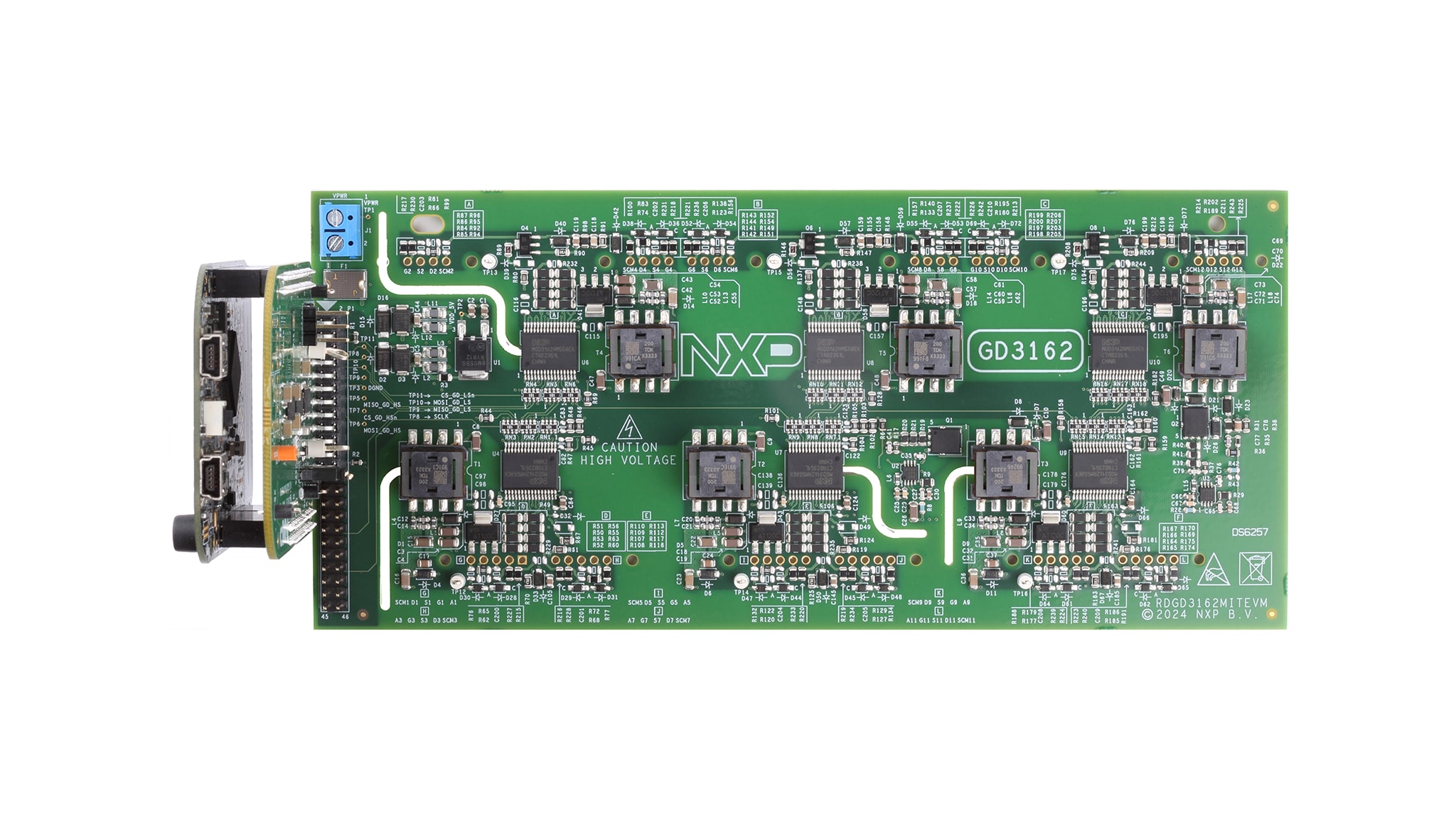
1. Out of the Box
The RDGD3162MITEVM is a fully functional three-phase inverter evaluation board populated with six GD3162 gate drivers with fault management and supporting circuitry. This board supports serial peripheral interface (SPI) daisy-chain communication for programming and communication with three high-side gate drivers and three low-side gate drivers independently, or all six gate drivers at the same time.
Working with the RDGD3162MITEVM requires the kit contents and a Windows PC workstation with the FlexGUI 2 for GD3162 software installed.
1.1 Kit Contents and Packing List
- Assembled and tested RDGD3162MITEVM (three-phase inverter populated with 5 V compatible gate-driver devices) board in an antistatic bag
- KITGD316xTREVB 3.3 V to 5.0 V translator with FRDM-KL25Z MCU board with micro‑USB cable
- Quick start guide
1.2 Additional Hardware
In addition to the kit contents, the following hardware is beneficial when working with this reference board.
- Microcontroller for SPI communication
- Compatible Mitsubishi CTF700CJ3D130 SiC MOSFET module
- DC-link capacitor compatible with SiC MOSFET module
- HV power supply with protection shield and hearing protection
- Current sensors for monitoring each phase current
- 12 V, 1.0 A DC power supply
- Four-channel oscilloscope with appropriate isolated probes
1.3 Windows PC Workstation
This reference design requires a Windows PC workstation. Meeting these minimum specifications produces great results when working with this evaluation board.
- USB-enabled computer with Windows 10 or higher operating system
1.4 Software
Installing software is necessary to work with this reference design. All listed software is available on the information page at RDGD3162MITEVM.
- FlexGUI 2 for GD3162 software for using with KITGD316xTREVB MCU/translator board
- S32S Design Studio IDE for power architecture
- Automotive Math and Motor Control Library (AMMCLib)
- FreeMASTER 2.0 runtime debugging tool
- Motor control application tuning (MCAT)
- Example code, GD3162 device driver notes and GD31xx device driver reference
2. Get Hardware
2.1 Board Features
- Capabilities to perform double-pulse and short-circuit tests on phase W using KITGD316xTREVB and FlexGUI 2; see phase W schematics and FlexGUI 2 pulse tab (Figure 18 and Figure 20)
- Evaluation board designed for and populated with GD3162 gate drivers and protection circuitry
- Capability to connect to Mitsubishi SiC specific modules for full three-phase evaluation and development
- Daisy-chain SPI communication × 3 - 2 channel (three high-side gate drivers and three low-side gate drivers)
- Flyback VCC power supply with GND reference negative VEE supply
2.2 Kit Featured Components
Refer to the GD3162 advanced IGBT/SiC gate-driver data sheet for specific information about pinout, pin descriptions, specifications and operating modes. The VPWR DC supply terminal is a low-voltage input connection for supplying power to the low-voltage nonisolated die and related circuitry. Power is typically supplied by the vehicle battery (12 V DC). The KITGD316xTREVB included with the kit (MCU and translator) can be attached to this board at the top of the dual-row header pin interface. All gate drivers can be accessed via SPI control using FlexGUI 2 software.

3. Install Software
Software for the RDGD3162MITEVM is distributed with the FlexGUI 2 for GD3162 software tool (available on nxp.com). Necessary firmware comes preinstalled on the FRDM-KL25Z with the kit.
If the user intends to test with other software or PWM, it is recommended to install this software as a backup or to help debugging.
3.1 Installing FlexGUI 2 for the GD3162 on a Computer
The latest version of FlexGUI supports the GD3162 gate driver. It is designed to run on any Windows 10 or higher operating system. To install the software, do the following:
- Go to the FlexGUI page and click Download
- When the FlexGUI 2 software page appears, click Download FlexGUI 2 for GD3162 Advanced Gate Driver Evaluation Software
- The FlexGUI 2 for GD3162 Wizard creates a shortcut. An NXP FlexGUI 2 icon appears on the desktop. Installing the device drivers overwrites any previous FlexGUI 2 installation and replaces it with a current version containing the GD3162 drivers. However, configuration files (.spi) from the previous version remain intact
4. Configure Hardware
4.1 Configure Hardware
The RDGD3162MITEVM with the KITGD316xTREVM attached is shown in Figure 2 using Windows-based PC and FlexGUI 2 for GD3162 software.
Suggested equipment needed for test:
- Rogowski coil high-current probe
- High-voltage differential voltage probes
- High sample rate digital oscilloscope with probes
- DC-link capacitor compatible with Mitsubishi CTF700CJ3D130 power module
- Mitsubishi CTF700CJ3D130 SiC power module
- Windows-based PC
- High-voltage DC power supply for DC link voltage
- Low-voltage 12 V DC power supply for VPWR
- Voltmeter for monitoring high-voltage DC-link supply
- Load coil for double-pulse testing (phase W only)

Design Resources
Board Information
RDGD3162MITEVM detailed information on this board, including documentation, downloads and software and tools RDGD3162MITEVM.
Additional References
In addition to the GD3162 product page, you may also want to visit: