
S32R294-CV
Active
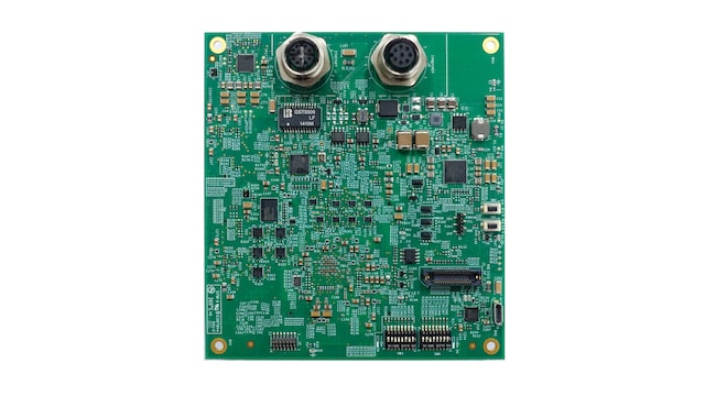
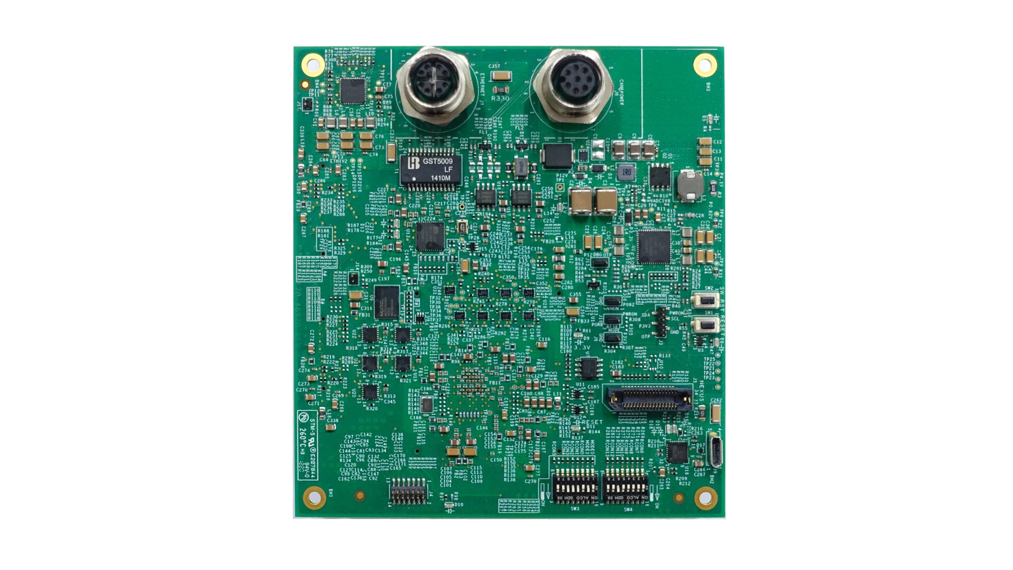
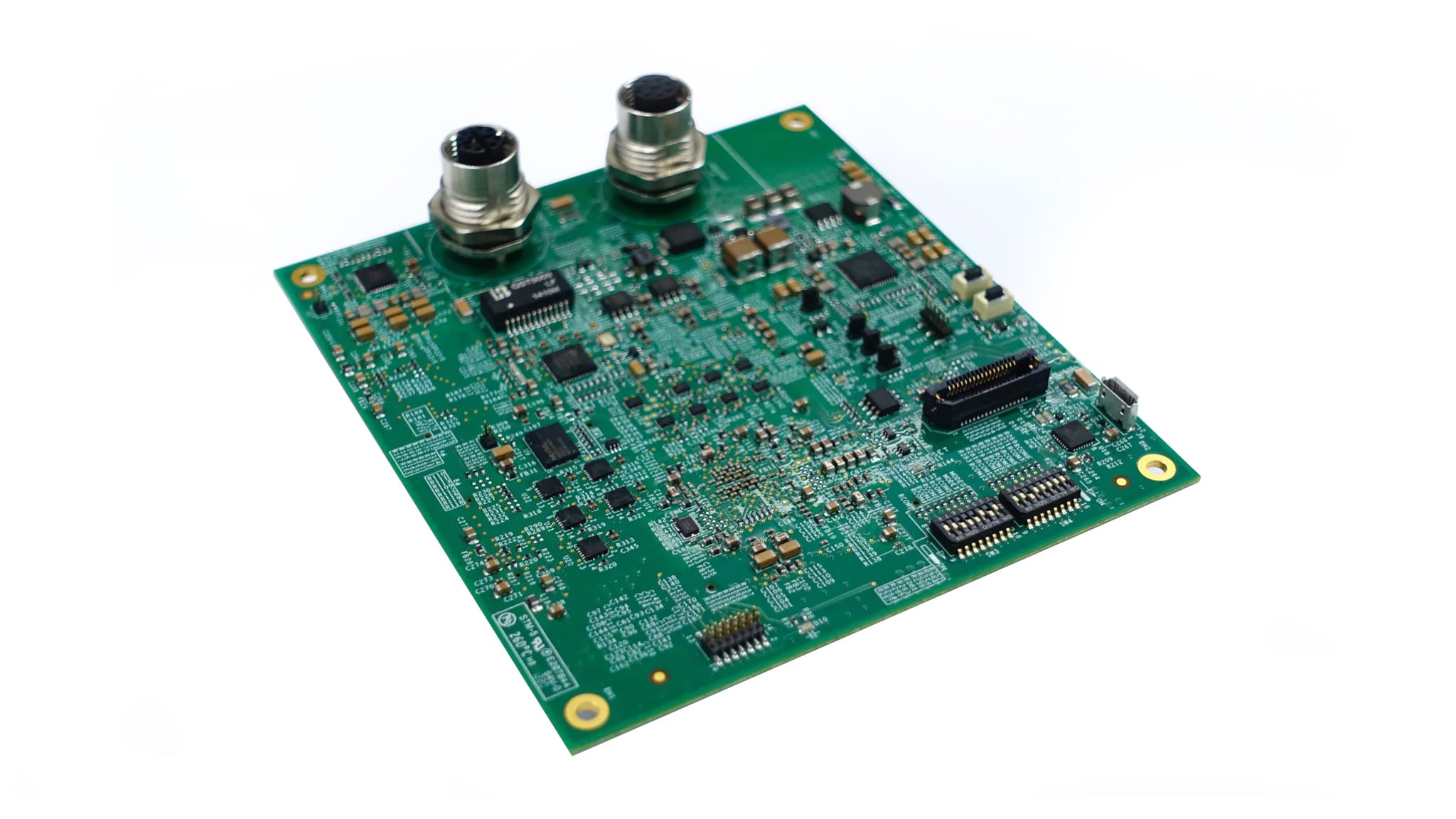
Radar Application Development Board.
Pending Stock
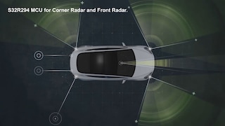
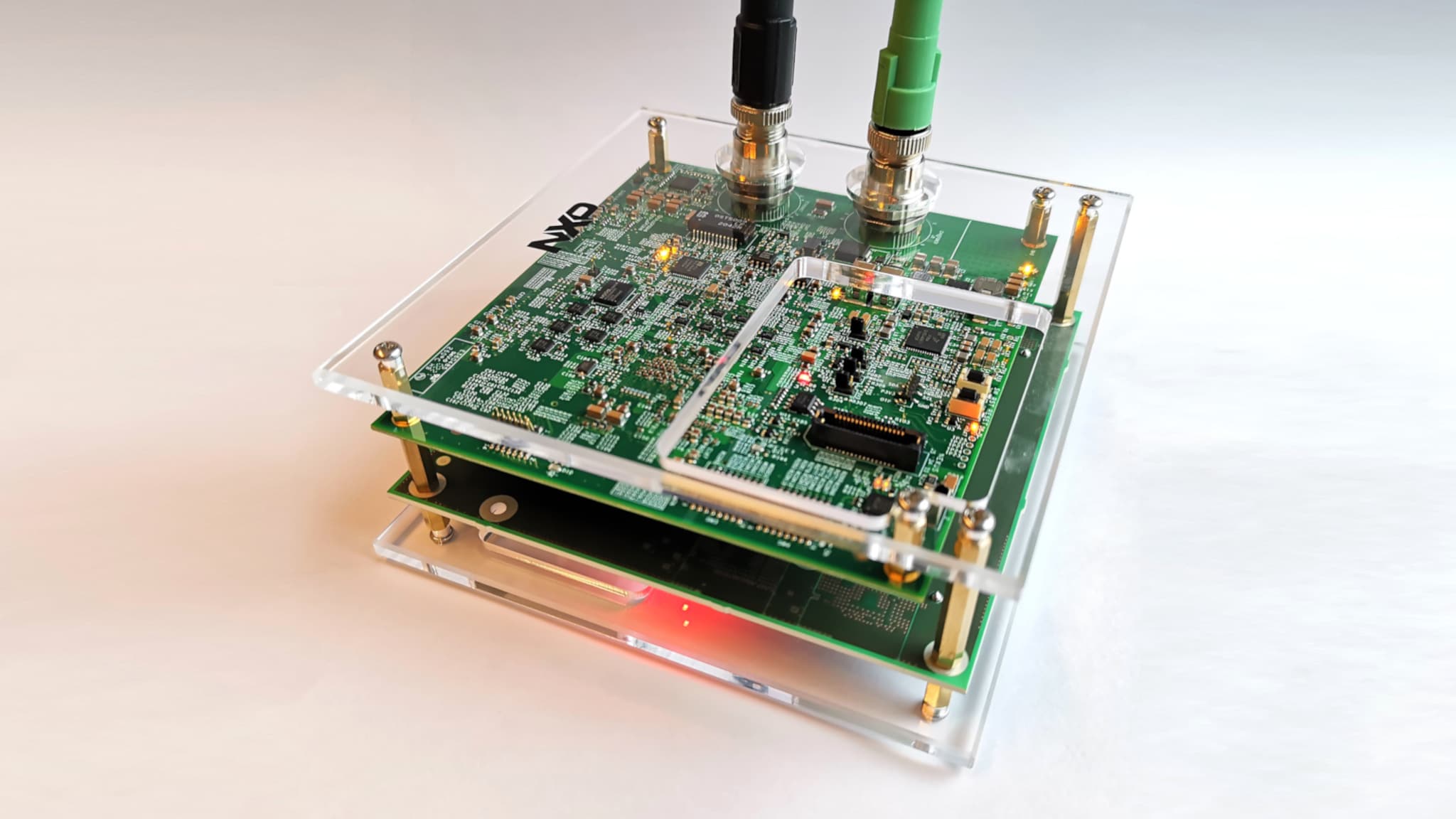
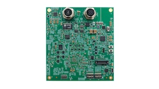
The S32R29 radar application development board (RADB) is intended to provide a flexible development platform for the automotive radar product based on NXP radar microprocessor S32R29. The S32R29 RADB unit kit can be easily used to evaluate and develop radar application software and processing algorithms.
For this radar application development board, a radar transceiver front-end board with 2x TEF82xx RF transceivers is available. The two boards feature combined power and high-speed signal connectors to provide direct connection of the MIPI-CSI2 and SPI interfaces, allowing high-speed data transfer to the MCU, along with SPI control signals and power domains to the RF transceiver. For more information on the TEF82xx front-end board, please check out TEF82-R294-KIT page.
Radar Application Development Board.
Quick reference to our documentation types
2 documents
Compact List
Quick reference to our software types.
1 software file
Note: For better experience, software downloads are recommended on desktop.
