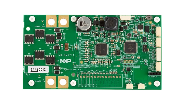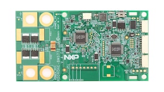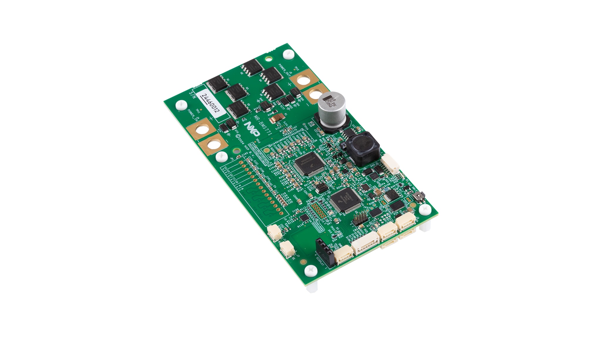
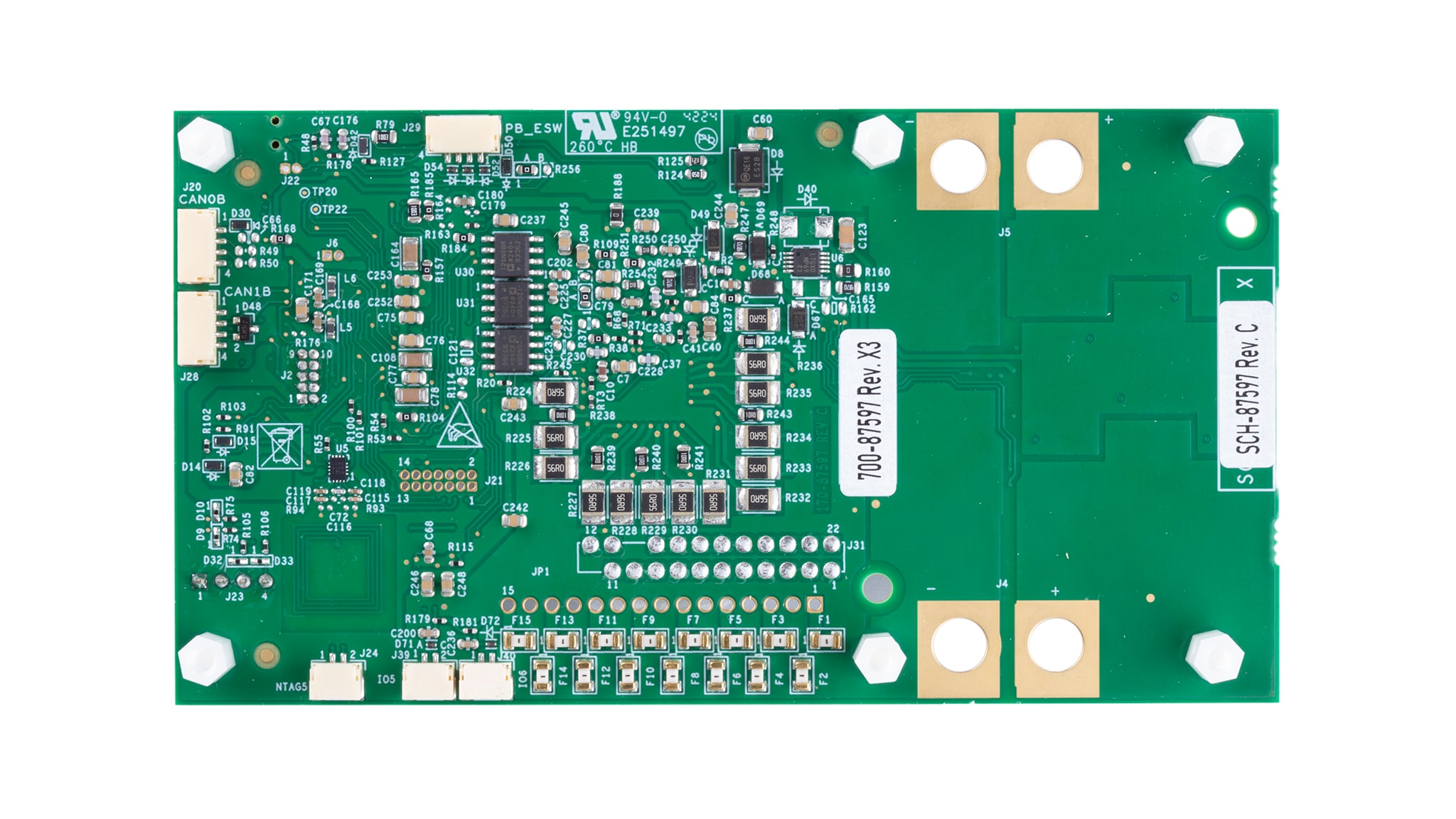

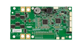
MR-BMS771
Active
Smart Battery Management for Mobile Robotics 7-14 Cells.
Kit Contains
- Assembled and tested MR-BMS771 in an antistatic bag
- Controller area network (CAN) bus termination resistor (DRONE-CAN-TERM)
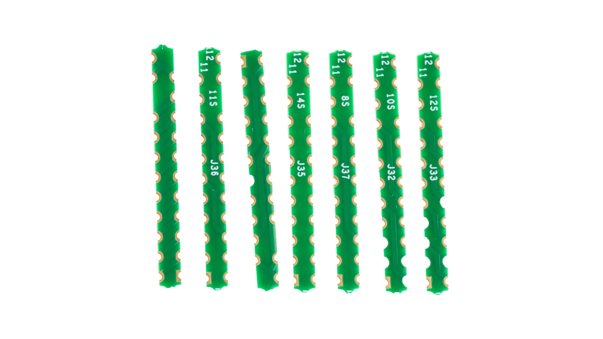
- Unmounted cell connectors for 8S to 14S with precrimped wires
- 4-pin JST-GH to 4-pin JST-GH 300 mm cable (CAN)
- Power input and power output connectors
- External thermistor with cable
- Small SSD1306 OLED display
- Quick start guide
- Small cell count selector interposer boards (7 cells to 14 cells)
- An NFC antenna
In Stock :3
Order from distributors