Quick Start Guide for FRDM-KW019032
Contents of this document
-
Plug It In
-
Get Software
-
Build, Run
-
Create
Sign in to save your progress. Don't have an account? Create one.
Purchase your FRDM-KW019032 | KW0x | Wireless
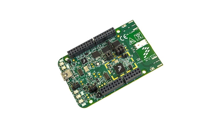
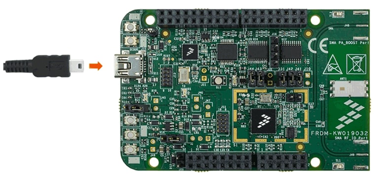
1. Plug It In
Let's take your FRDM-KW019032 for a test drive!
2. Get Software
In this step, you will be guided to download the software and tools required to build and run the connectivity solutions.
2.1 Download KW01 Connectivity Software
The KW01 Connectivity Software package integrates the Kinetis Software Development Kit 1.3 and all the wireless connectivity stacks required to develop your solution using IEEE 802.15.4 and SMAC wireless connectivity stacks.
Download the KW01 Connectivity Software v1.0.0 for your computer.
2.2 Install Your Toolchain
IAR Embedded Workbench for Arm (EWARM) version 7.40.2 or later is the development toolchain used to deploy software applications using the NXP connectivity stacks. NXP provides example EWARM workspace projects for you to start your development.

Get IAR Embedded Workbench for Arm
Want to use a different toolchain?
Right now, the only supported toolchain is IAR Embedded Workbench for Arm; we are currently working on the enablement of NXP KDS for connectivity stacks.
2.3 PC Configuration
Many of the example applications output data over the MCU UART so you'll want to make sure that the driver for the board's virtual COM port is installed. Before you run the driver installer, you MUST have the board plugged in to your PC.
With the serial port driver installed, run your favorite terminal application to view the serial output from the MCU's UART. Configure the terminal to 115,200 baud rate, 8 data bits, no parity and 1 stop bit. To determine the port number of the FRDM-KW019032's virtual COM port, open the device manager and look under the "Ports" group.
Not sure how to use a terminal application? Try one of these tutorials: Tera Term Tutorial, PuTTY Tutorial.
3. Build, Run
3.1 Select Connectivity Stack
Each of the Wireless Connectivity Stack comes with a list of demo applications and driver examples ready to be compiled and run.
Select the Connectivity Stack that you want to explore.
SMAC
Browse to the examples\smac folder to see the application demos:
<connectivitysoftware_install_folder>\KW01_Connectivity_Software_v1.0.0\ConnSw\examples\smac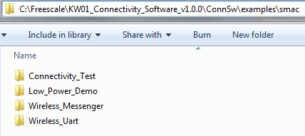
If you are interested in running the preprogrammed connectivity test demo that comes with your board, go to Connectivity Test Application.
IEEE 802.15.4
Browse to the examples\ieee_802_15_4 folder to see the application demos:
<connectivitysoftware_install_folder>\KW01_Connectivity_Software_v1.0.0\ConnSw\examples\ieee_802_15_4If you are interested in running the preprogrammed TSCH Application that comes with your board, go to MKW01 Connectivity Test Application.
3.2 Build, Run and Debug Wireless Connectivity Examples
You probably want to build and debug a demo by yourself. Use the guide below to learn how to build and debug an example application using one of the Wireless Connectivity Stacks provided by NXP.
SMAC
These steps show how to:
- Build the platform libraries required by the application demo
- Build the demo application
- Download and run the demo application
The example used below is for the SMAC Connectivity Test demo, but these steps can be applied to any of the Wireless Connectivity demo applications.
Build the Platform Library
- Open the
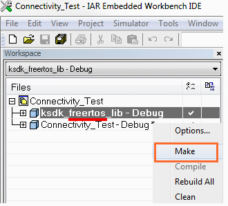
Connectivity_Test.ewwIAR workspace - After the workspace is open, some projects are shown: one for the KSDK platform library and one for the demo application. Build ALL the required KSDK libraries by right-clicking on the SDK projects and click on 'Make'
<connectivitysoftware_install_folder>\KW40Z_Connectivity_Software_<version>\ConnSw\examples\smac\Connectivity_Test\usbkw40z\FreeRTOS\build\iar\Connectivity_Test.eww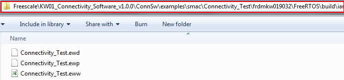
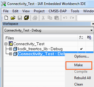
Build the Application Demo
- Select and build the "Connectivity_Test - Debug" project
Download and Run the Application Demo
- Connect your FRDM-KW019032 board to your PC
Open a Terminal Emulator program and open a session to your FRDM-KW019032 COM port. Configure the terminal with these settings:
- 115,200 baud rate
- No parity
- 8 data bits
- 1 stop bit
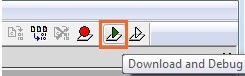
- Click on "Download and Debug" icon to flash the board
The following output will be displayed

If you don't see this output, verify your terminal settings and connections
-
Refer to
<connectivitysoftware_install_folder>
            \KW01_Connectivity_Software_v1.0.0\ConnSw\doc\MKW01SMACDAUG.pdf
- "KW01 Simple Media Access Controller (SMAC) Demonstration Applications" document for instructions on how to run all the demo applications
IEEE 802.15.4
These steps show how to:
- Build the platform libraries required by the application demo
- Build the demo application
- Download and run the demo application
The example used below is for "MyWirelessApp" application demo, but these steps can be applied to any of the Wireless Connectivity demo applications.
Build the Platform Library
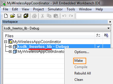
- Open the
MyWirelessAppCoordinator.ewwIAR workspace - After the workspace is open, some projects are shown: some for the KSDK platform libraries and one for the demo application. Build ALL the required KSDK libraries by right-clicking on the SDK projects and click on 'Make'
<connectivitysoftware_install_folder>\KW01_Connectivity_Software_v1.0.0\ConnSw\examples\ieee_802_15_4\MyWirelessApp\Coordinator\frdmkw019032\FreeRTOS\build\iar\MyWirelessAppCoordinator.eww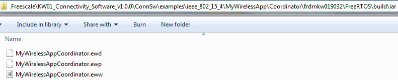
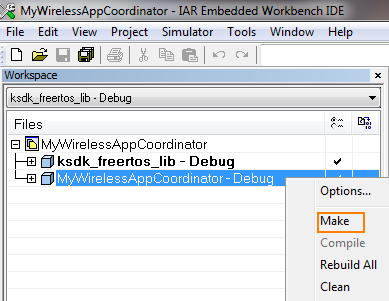
Build the Application Demo
- Select and build the "MyWirelessAppCoordinator - Debug"project
Download and Run the Application Demo
- Connect your FRDM-KW019032 board to your PC
-
Open a Terminal Emulator program and open a session to your FRDM-KW019032 COM port. Configure the terminal with these settings:
- 115,200 baud rate
- No parity
- 8 data bits
- 1 stop bit
- Click on "Download and Debug" icon to flash the board
The following output will be displayed

If you don't see this output, verify your terminal settings and connections
- Repeat all steps with "MyWirelessApp" End Device demo application to communicate with this device
- Refer to
<connectivitysoftware_install_folder>\KW01_Connectivity_Software_v1.0.0\ConnSw\doc\802154MPDAUG.pdf- "NXP 802.15.4 Media Access Controller (MAC) Demo Applications" document for instructions on how to run all the demo applications
4. Create
4.1 Create your own Project
NXP provides a tool called "Project Cloner" which will allow you to copy an existing demo to use it as a base for your own development, keeping the original demo app sources for reference.
4.2 Run the Project Cloner
To create a clone of an example project:
- Launch the Project Cloner executable which is located at:
- Verify the Project Cloner GUI is displayed
- Codebase path: Connectivity Stack path folder
- Clone example app: Demo Applications available for the selected stack
- Clone configuration: Select from the available development boards, RTOS and Toolchains
- Cloned app name: Name that the cloned project will have
- Destination root path: Folder where the cloned project will be created
-
Select:
- Clone application files only: Clone the app, boards, and platform files in the stack installation - the other files will be linked from the stack installation folder using an environment variable
- Clone full codebase: Clone the full files, folders and libraries
- Select an example demo to be cloned and fill the options
- Press "Clone Project" to create the cloned application. A message log will be displayed in the log box as files are being copied. (Destination files will be overwritten if they already exist)
<connectivitysoftware_install_folder>\ConnSw\tools\project_cloner\project_cloner.exe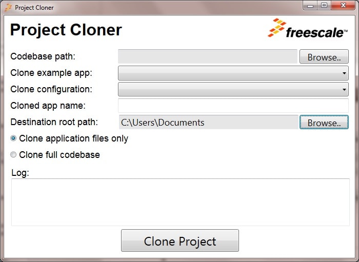
4.3 Open Your Project
Your new project will be located in path specified in the previous step. Open the project in IAR Embedded Workbench for Arm by using the same process described in Section 3.
4.4 Start Creating your own Application
Modify your recently cloned application to start your own design!
For more information about the application and the APIs available, please, look at the "Applications Development Guide".
4.5 Kinetis SDK Platform
The Wireless Connectivity Stack platforms make use of the Kinetis SDK low level drivers, take a look into the SDK Demo Applications if you want to add a driver that is not currently used on the Connectivity Demo Applications.
Tera Term Tutorial
Tera Term Tutorial
Tera Term is a very popular open source terminal emulation application. This program can be used to display information sent from your NXP development platform's virtual serial port.
- Download Tera Term from SourceForge. After the download, run the installer and then return to this webpage to continue
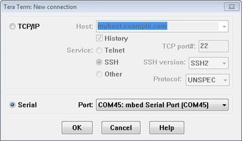
- Launch Tera Term. The first time it launches, it will show you the following dialog. Select the Serial option. Assuming your board is plugged in, there should be a COM port automatically populated in the list
- Configure the serial port settings (using the COM port number identified earlier) to 115,200 baud rate, 8 data bits, no parity and 1 stop bit. To do this, go to Setup → Serial Port and change the settings
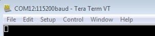
- Verify that the connection is open. If connected, Tera Term will show something like below in its title bar
- You're ready to go
PuTTY Tutorial
PuTTY Tutorial
PuTTY is a popular terminal emulation application. This program can be used to display information sent from your NXP development platform's virtual serial port.
- Download PuTTY using the button below. After the download, run the installer and then return to this webpage to continue
- Launch PuTTY by either double clicking on the *.exe file you downloaded or from the Start menu, depending on the type of download you selected
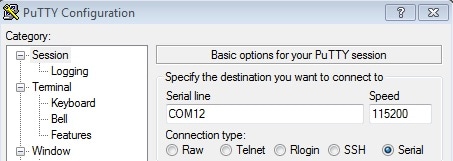
- Configure in the window that launches, select the Serial radio button and enter the COM port number that you determined earlier. Also enter the baud rate, in this case 115,200
- Click Open to open the serial connection. Assuming the board is connected and you entered the correct COM port, the terminal window will open. If the configuration is not correct, PuTTY will alert you
- You're ready to go
Connectivity Test Application
The Connectivity Test Application is a SMAC based Demo Application which provides the user with means to test basic transmission-reception functionalities along with several advanced testing features based on the ASP and SMAC APIs.
Configuration
The runtime configuration is performed using shortcut keys which are available in most of the application's menus. The menus or tests will change their behavior based on what settings are applied.
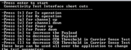
- 't' - brings up the configuration menu for the transmitter in both PER and Range tests
- 'r' - brings up the configuration menu for the receiver in both PER and Range tests
- 'q' - increments channel number [11-26]
- 'w' - decrements channel number [11-26]
- 'a' - increments output power value
- 's' - decrements output power value
- 'n' - increments the length of the payload (used in PER TX and Transmission Control)
- 'm' - decrements the length of the payload (used in PER TX and Transmission Control)
- 'k' - increments the CCA threshold for the Carrier Sense test
- 'l' - decrements the CCA threshold for the Carrier Sense test
Application Usage
The Connectivity Test Application has four main features:
- Continuous Tests: Allows you to test the RF performance of the transceiver for basic transmitter and receiver functionality. The Test Mode application is a collection of modes consisting of the following tests
- Packet Error Rate: This menu depends on the 'r' or 't' shortcut key. Two boards are required to run this test, one of the boards shall be set in RX and the other in TX
- Range Test: This menu depends on the 'r' and 't' shortcuts. Two boards are required to run this test; the test is started and stopped only by user intervention and during its execution it will display the link quality for each received packet
-
Carrier Sense and Transmission Control:
This menu allows the user to choose between two tests:
- The Carrier Sense test performs ED continuously until the ED value is above the CCA threshold and then transmit a packet which contains pseudo-random data with the payload size configured using 'n' and 'm' shortcuts
- The Transmission Control test displays a selection menu for number of packets identical with the one in PER TX test and then it prompts the user to enter the inter-packet delay. After that, the application will start sending the selected number of packets with the selected inter-packet delay, using pseudo-random data for the payload with the size configured with 'n' and 'm' shortcuts
- For additional details on how to run the Connectivity Test Application, please refer to the SMAC's Demonstration Applications User's Guide
MKW01 Connectivity Test Application
Time-Slotted Channel Hopping Demo
Your FRDM-KW019032 boards are loaded with a MAC TSCH demo that allows network nodes to hop on a set of channels based on a time division manner, the mechanism being Time Slotted Channel Hopping (TSCH). TSCH allows networks nodes to exchange data frames on various frequencies being recommended for regions where local regulations limit the continuous transmission time on a frequency of a node to a certain duration.
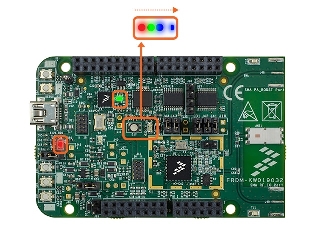
The TSCH demo will start with a sequence of LEDs indicating that the application is in the pre-MAC start state.
Two FRDM-KW01 boards are needed to run this demo.
The available demo applications are:
- TSCH Demo PAN Coordinator: Press
SW1, the RGB LED will turn on Red indicating that the device was configured as a coordinator - TSCH Demo End Device: Press
SW2orSW3orSW4, the RGB LED will turn on Blue indicating that the device was configured as an End Device
After configuring both devices as a Coordinator and as an End Device respectively, the
application will start in a moment. In both boards, the RGB LED will toggle with a
reception and
D8 LED will toggle with a transmission. To monitor the traffic, one or multiple sniffers
can be used set on the channels the two devices hop on (US ISM Band).
This application also can be used to test the range of the boards by watching that the LEDs continue toggling with the distance.
Design Resources
Board Information
Chip Documents
Support
Forums
Connect with other engineers and get expert advice on designing with the FRDM-KW019032 on one of our community sites.