Getting Started with the FRDMGD31ECNEVM Evaluation Kit
Contents of this document
-
Out of the Box
-
Plug It In
-
Configure Hardware
-
Get Software
Sign in to save your progress. Don't have an account? Create one.
Purchase your FRDMGD31ECNEVM | Half-Bridge Evaluation Kit
1. Out of the Box
The NXP analog product development boards provide an easy-to-use platform for evaluating NXP products. The boards support a range of analog, mixed-signal and power solutions. They incorporate monolithic integrated circuits and system-in-package devices that use proven high-volume technology. NXP products offer longer battery life, a smaller form factor, reduced component counts, lower cost and improved performance in powering state-of-the-art systems.
This page will guide you through the process of setting up and using the FRDMGD31ECNEVM board.
1.1 Kit Contents/Packing List
The FRDMGD31ECNEVM contents include:
- Assembled and tested FRDMGD31ECNEVM board in an anti-static bag
- FRDM-KL25Z connected to translator board (3.3 V to 5.0 V)
- Cable, USB type A male/type mini B male 3 ft
- Quick Start Guide
1.2 Additional Hardware
In addition to the kit contents, the following hardware is necessary or beneficial when working with this kit.
- IGBT or SiC MOSFET module in EconoDUAL™ package
- DC link capacitor compatible with IGBT or SiC MOSFET module
- 50 mil jumpers for configuration
- 50 µH, high current air core inductor for double pulse testing
- HV power supply with protection shield and hearing protection
- 25 V, 1.0 A DC power supply
- Pulse generator
- TEK MSO 4054 500 MHz 2.5 GS/s 4-channel oscilloscope
- Rogowski coil, PEM Model CWT Mini HF60R or CTW MiniHF30 (smaller diameter)
- Two isolated high voltage probes (CAL Test Electric CT2593-1, LeCroy AP030)
- Four low voltage probes
- Two digital voltmeters
1.3 Windows PC Workstation
This evaluation board requires a Windows PC workstation. Meeting these minimum specifications should produce great results when working with this evaluation board.
- Windows XP or higher operating system
2. Plug It In
2.1 Board Features
- Capability to connect to MOSFET or IGBT modules with an EconoDUALTM footprint for half-bridge evaluations
- Daisy chain SPI communication capable
- Power supply and fail-safe jumper configurable
- Easy access power, ground and signal test points
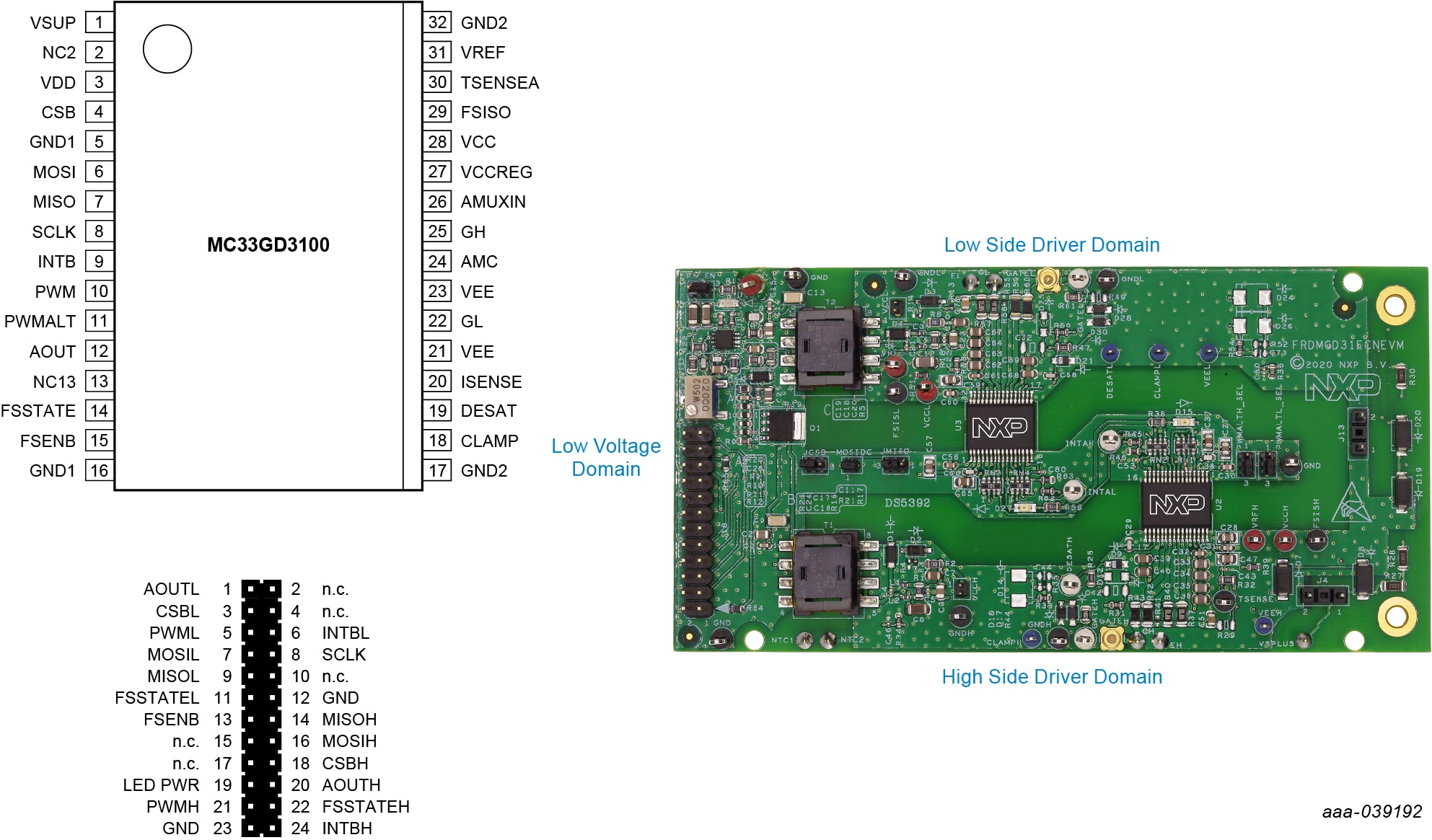
2.2 Board Description
The FRDMGD31ECNEVM is a half-bridge evaluation kit populated with two GD3100 single channel IGBT gate drive devices on a half-bridge evaluation board with pin configuration compatible with Econo IGBTs.
The kit includes the Freedom KL25Z microcontroller hardware for interfacing a PC installed with SPIGen software for communication to the SPI registers on the GD3100 gate drive devices in either daisy chain or standalone configuration.
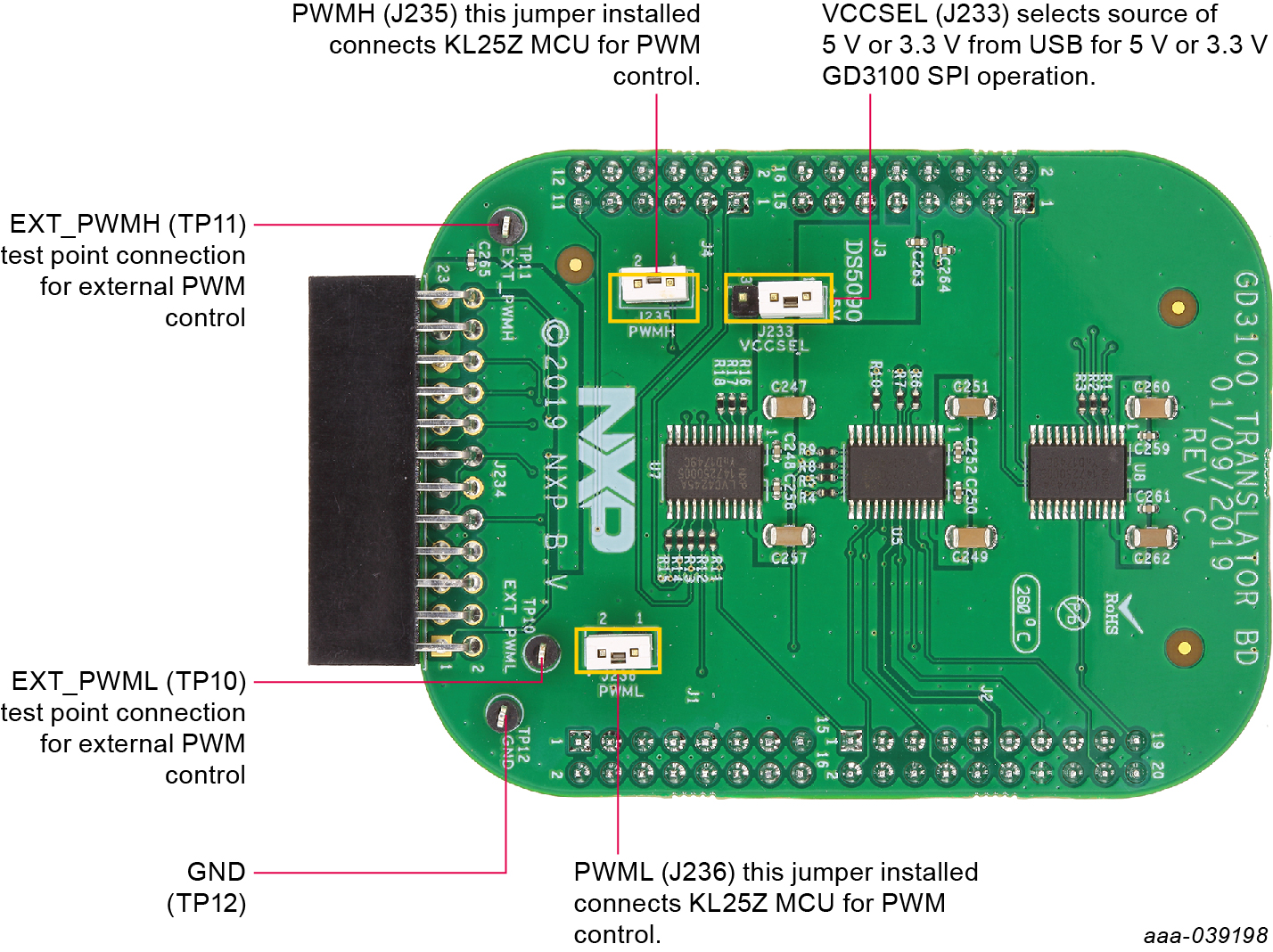
2.3 3.3 V to 5.0 V Translator Board
GD3100 translator enables level shifting of signals from 3.3 V to 5.0 V SPI communication.
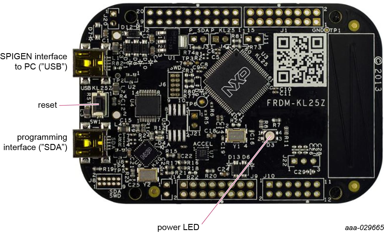
2.4 Kinetis KL25Z Freedom Board
The Freedom KL25Z is an ultra-low-cost development platform for Kinetis® L Series KL1x (KL14/15) and KL2x (KL24/25) MCUs built on Arm® Cortex®-M0+ processor.
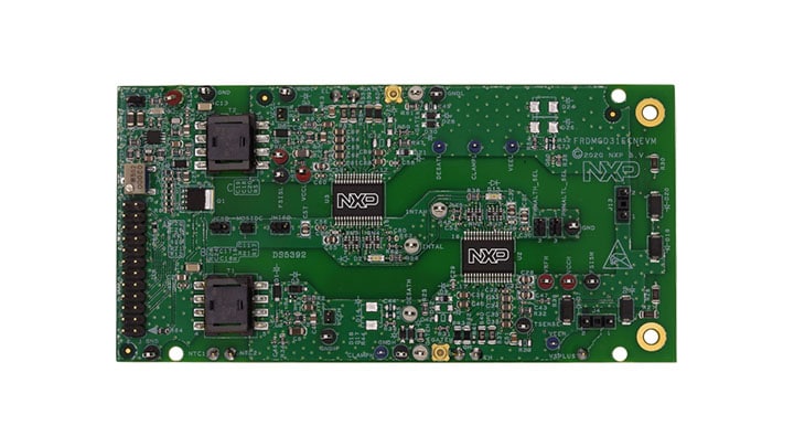
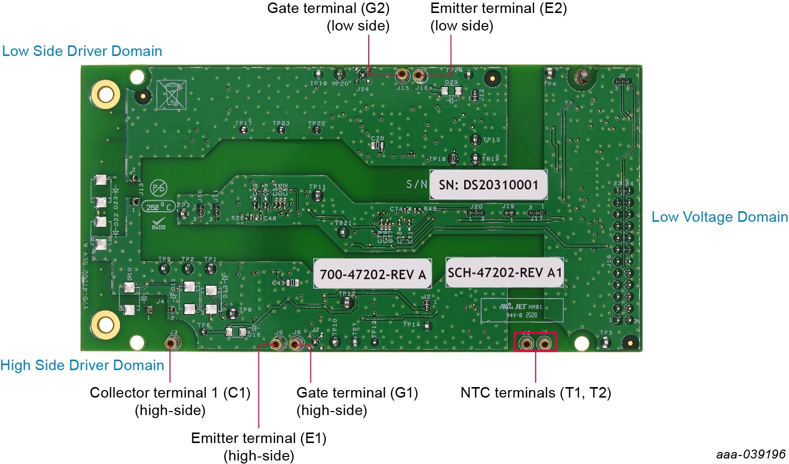
2.5 Board Components
Overview of the FRDMGD31ECNEVM half-bridge evaluation board.
3. Configure Hardware
3.1 Configure the Hardware for Startup
The following figure presents a typical hardware configuration.
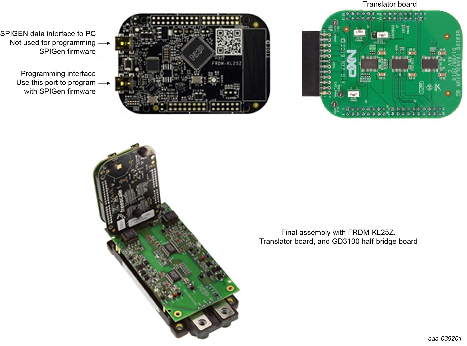
To configure the hardware and workstation, complete the following procedure:
- Connect FRDM-KL25Z and the translator board with FRDMGD31ECNEVM half-bridge evaluation board by attaching to the 24-pin header in the correct orientation
- Attach the FRDMGD31ECNEVM to an IGBT module as desired with socket pins firmly on the module pin connections. Half-bridge board jumpers will be pre-installed from the factory and configured for SPI communication in a non-daisy chain SPI configuration
- Attach 12 V DC power supply to VPWR connection on half-bridge board and low voltage domain GND test point connection on half-bridge board. Note: Be sure to ground to low voltage domain for VPWR connection.
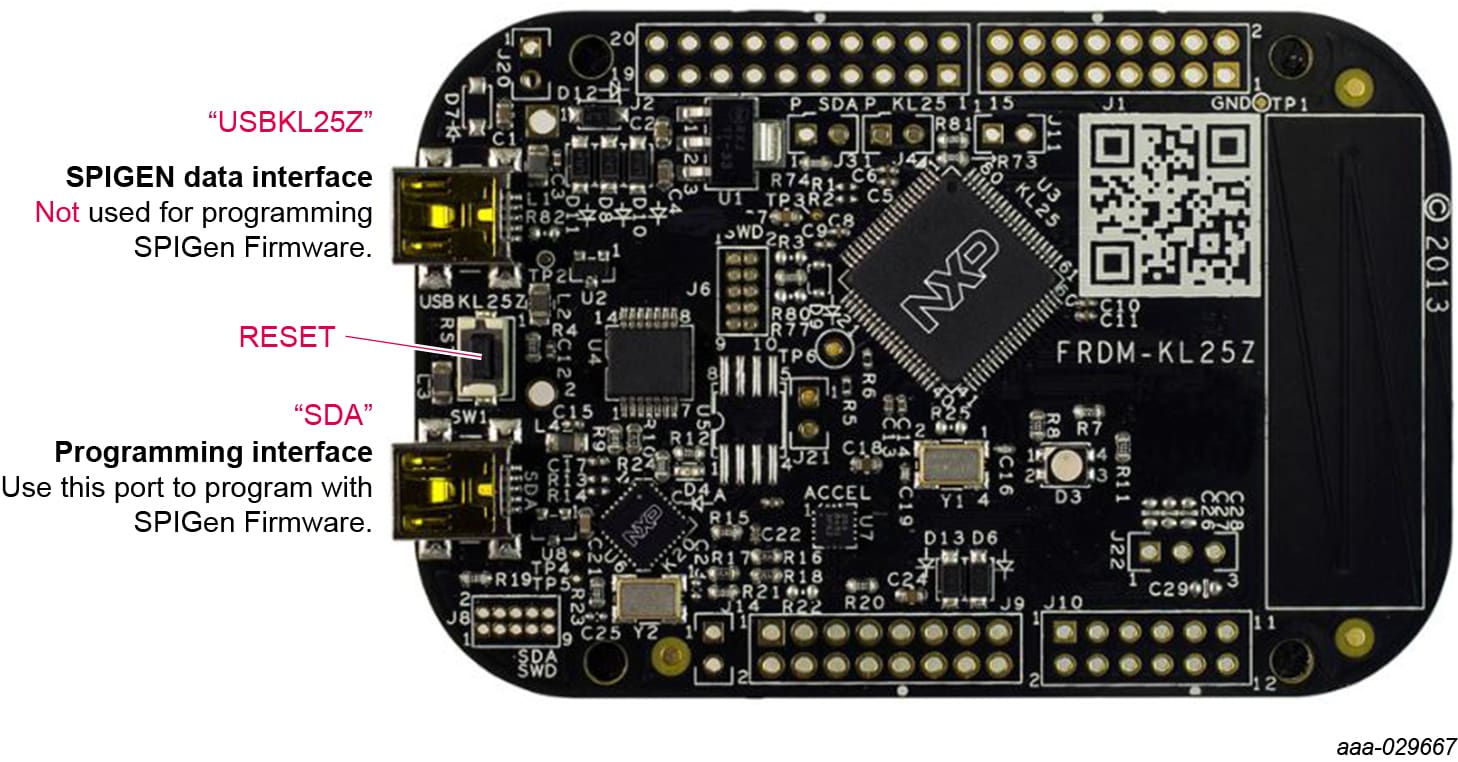
- Connect USB cable from USBKL25Z USB mini connection to Windows-based PC USB port. KL25Z will be pre-installed with firmware from factory
- With SPIGEN GUI installed and application running on Window-based PC, reconnect USB cable. A pop-up should appear indicating connection to the FRDM-KL25Z board
- Enable the 12 V DC power supply to the VPWR low voltage domain. The SPIGEN GUI enables you to READ and WRITE registers on each GD3100 gate driver on either SPI0 (low-side) or SPI1 (high-side)
- Observe VCCL and VCCH voltage levels on the low-side and high-side high voltage domains respectively. These are set to provide the gate drive high levels from the fly-back transformers and are isolated from the low voltage domain and from each other and have isolated grounds. VCCL (low-side) and VCCH (high-side) will be at ~17 V with VEE set to ~-3.3 V, which will be the swing levels of the gate driver PWM signals
- With a DC link voltage supplied and an inductive load connected to the IGBT module, double pulse and short-circuit testing can be performed utilizing the SPIGEN pulse test functions in conjunction with the FRDMGD31ECNEVM half-bridge evaluation board. Use test points to observe desired signals
4. Get Software
4.1 Preparing Graphical User Interface Operating Environment
-
Install the firmware and MCU code
- The kit ships with KL25Z MCU firmware already installed. If for any reason the KL25Z MCU firmware needs
to be re-installed, follow this procedure. Hold down the reset button on the KL25Z board and connect a
mini USB B cable from the PC to the programming interface SDA USB port. Release the reset button. The PC
shows a drive called
E:/BOOTLOADERor something similar. Copy the SDA file (MSD- DEBUG-FRDM-KL25Z_Pemicro_v118.SDA) to theE:/BOOTLOADERdrive - Unplug and re-plug the USB cable to the same location to restart and activate the new firmware (do not
hold the reset button this time). The drive name changes to
E:/FRDM-KL25Zor something similar. Copy the file UsbSpiDongleKL25Z_GD3100_545.srec to theE:/FRDM-KL25Zdrive. Unplug USB cable. Firmware files are available with SPIGEN install, which can be downloaded from NXP.com and can be found in SPIGEN install directory folder
- The kit ships with KL25Z MCU firmware already installed. If for any reason the KL25Z MCU firmware needs
to be re-installed, follow this procedure. Hold down the reset button on the KL25Z board and connect a
mini USB B cable from the PC to the programming interface SDA USB port. Release the reset button. The PC
shows a drive called
- Run SPIGEN SPI generator software installer to install SPIGEN on PC
-
Run SPIGEN with KL25Z board connected
- Connect the PC to the mini USB B cable into the “USBKL25Z” USB port on the KL25Z board
- Open the SPIGen software on the PC. At the bottom of the page, you should see SPI dongle Firmware Ver. 5.4.7 or later
Design Resources
Board Information
Additional References
In addition to our GD3160: Advanced Single-Channel High-Voltage Isolated Automotive Gate Driver for SiC MOSFETs/IGBTs page, you may also want to visit:
Gate driver pages:
Application pages:
Tool pages:
Hardware pages:
Software pages: