Getting Started with the KITPF8150FRDMEVM and KITPF8250FRDMEVM Evaluation Boards
Contents of this document
-
Out of the Box
-
Get to Know the Hardware
-
Configure Hardware
-
Install Software
Sign in to save your progress. Don't have an account? Create one.
Purchase your KITPF8X50FRDMEVM
1. Out of the Box
The KITPF8150FRDMEVM/KITPF8250FRDMEVM is an evaluation board composed of all the necessary headers, jumpers and signal test points to quickly evaluate NXP products.
This document is intended to help you quickly set up, configure and operate the KITPF8150FRDMEVM/KITPF8250FRDMEVM evaluation board.
1.1 Kit Contents and Packing List
To get started with the KITPF8150FRDMEVM or the KITPF8250FRDMEVM, you will need the kit contents, some additional hardware and a Windows PC workstation with software installed. The contents include:
- Assembled and tested evaluation board and preprogrammed FRDM-KL25Z microcontroller board in an antistatic bag
- 3.0 ft. USB-STD A to USB Mini-B or USB Type-C depending on the FRDM-KL25Z board version
- Quick Start Guide
1.2 Additional Hardware
In addition to the kit contents, the following hardware is necessary and beneficial when working with this board:
- Power supply with rated for 3.0 V to 5.0 V with an initial current limit of 1.0 A (maximum current consumption can be up to 7.0 A)
1.3 Windows PC Workstation
This evaluation board requires a Windows PC workstation. Meeting these minimum specifications should produce great results when working with this evaluation board:
- USB-enabled computer with Windows 7 to 11
1.4 Software
Installing software is necessary to work with this evaluation board. Download and install the latest version of the Graphical User Interface (GUI) for NXP Automotive PMIC products on the PC.
The evaluation board (EVB) can be operated easily using the GUI. Contained in this document is an example using Rev 10.0.0. One version of the PF8x firmware can be found in the GUI folder. This version may need to be updated to work with the FRDM-KL25Z auxiliary board.
1.5 User Manual
Refer to the UM12404 and KITPF8150FRDMEVM/KITPF8250FRDMEVM evaluation board user manual for full evaluation board functionality.
2. Get to Know the Hardware
2.1 Board Overview
The KITPF8150FRDMEVM or the KITPF8250FRDMEVM provides an easy-to-use platform for evaluating NXP products. The boards support a range of analog, mixed-signal and power solutions. They incorporate monolithic integrated circuits (IC) and system-in-package devices that use proven high-volume technology. NXP products offer longer battery life, a smaller form factor, reduced component counts, lower cost and improved performance in powering state-of-the-art systems.
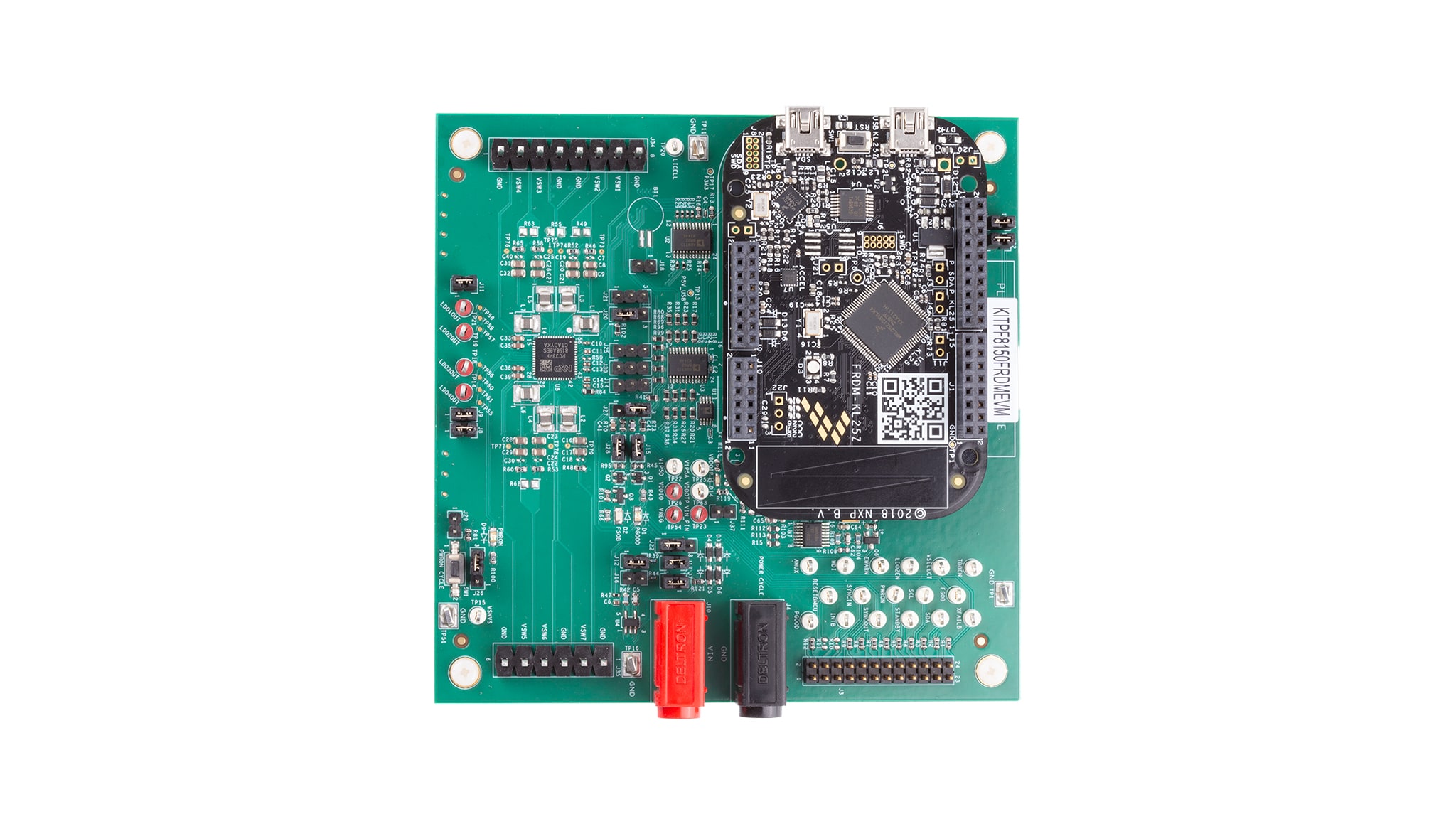
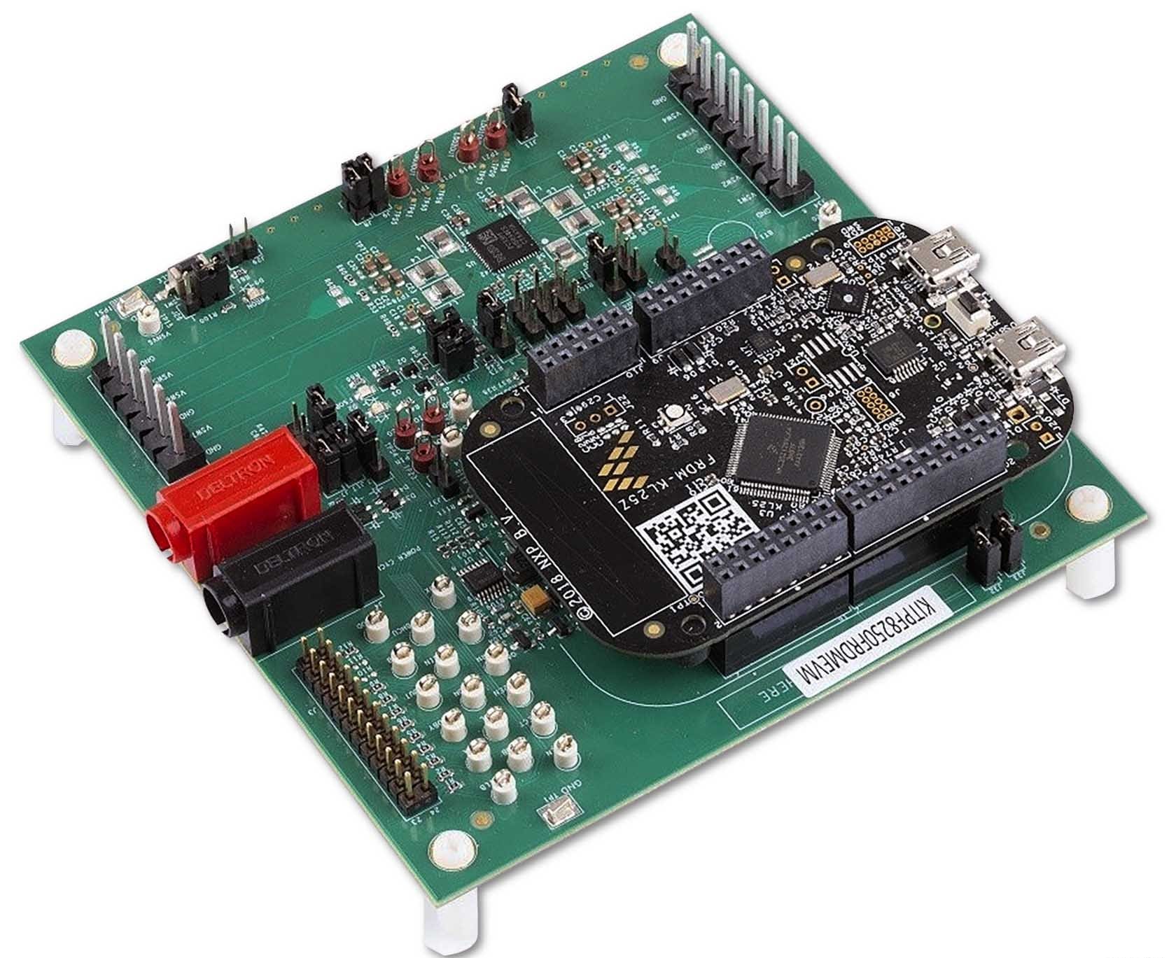
These customer evaluation boards feature the PF8150/PF8250 power management integrated circuit (PMIC). The kits integrate all the hardware needed to fully evaluate the PMIC. They integrate a communication bridge based on the FRDM-KL25Z development board to interface with the GUI software interface to fully configure and control the PF8150/PF8250 PMIC.
2.2 Board Features
Buck regulators
SW1,SW2,SW3,SW4,SW5,SW6: 0.4 V to 1.8 V; 2500 mA; 1.5 % accuracy and dynamic voltage scaling and single-, dual-, triple- or quad-phase configurationSW7; 1.0 V to 4.1 V; 2500 mA; 2 % accuracy- Configurable voltage target termination (VTT) termination mode on SW6
- Programmable current limit
- Spread-spectrum and manual tuning of switching frequency
LDO regulators
- 4x low drop-out (LDO) regulator 1.5 V to 5.0 V, 400 mA: 3 % accuracy with optional load-switch mode
- Selectable hardware/software control on LDO2
Real-Time Clock (RTC) supply
- Voltage for secure non-volatile storage (VSNVS) 1.8 V/3.0 V/3.3 V, 10 mA
- Battery-backed memory including coin-cell charger with programmable charge current and voltage
System features
- 2.7 V to 5.5 V operating input voltage range
- USB-to-inter-integrated circuit (I²C) communication via the FRDM-KL25Z interface
- Selectable hardwire default PMIC configuration or one-time programmable (OTP) / try-before-buy (TBB) operation
- Fast mode I²C communication at 400 kHz (high-speed operation supported by PMIC)
- Advanced system monitoring/diagnostic via PMIC and/or system analog multiplexer (AMUX)
- Primary/secondary interface connector
- Onboard I/O regulator with 1.8 V/3.3 V selectable output voltage
2.3 Board Description
The KITPF8150FRDMEVM/KITPF8250FRDMEVM are hardware evaluation boards that allow the full evaluation of the PF8150/PF8250. The PF8150/PF8250 family of devices feature a PMIC designed for high-performance applications based on NXP's i.MX 8 and S32x processors, but also on other non-NXP processors. It features seven high-efficiency buck converters and four linear regulators for powering the processor, memory and miscellaneous peripherals.
Built-in OTP memory stores key startup configurations to drastically reduce external components that are used to set output voltage and sequence of external regulators. Regulator parameters are adjustable through high-speed I²C after startup offering flexibility for different system states.
The PF8150/PF8250 family is comprised of two versions of this PMIC to address different market needs:
- PF8250 is the flagship version of this family providing a full-feature PMIC with integrated functional safety mechanism to comply with the ISO 26262 standard and provide a powerful and flexible solution for ASIL B/D automotive modules
- PF8150 is the non-safety version of this product, providing all the power management and digital control included in PF8250, without the functional safety overhead, to provide a more economic platform for non-safety systems
The key features are listed in Table 1.
| Device | Description | Features |
|---|---|---|
| PF8150 | PMIC for high-performance processing applications |
|
| PF8250 | PMIC for high-performance processing applications |
|
The Figure 1 consists of a multiple board with FRDM-LKL25 as shown in the final assembly below.
3. Configure Hardware
3.1 Hardware Configuration
This section summarizes the overall setup, however the user guide provides a more detailed description. The suggested equipment needed for testing is as follows:
- 3.0 V to 5.0 V power supply (using banana jacks)
- Computer
- Mini USB Type-A cable or USB Type-C cable depending on the KL25Z board
3.2 Configuration Image
3.3 Device Considerations
It is recommended to learn about the device and its specifications prior to operating the boards. The device has a high level of flexibility due to parameter configuration available in the OTP. This impacts the functionality of the device, which is key to understanding how the parameters are programmed on the device.
3.4 Setting Up the Board
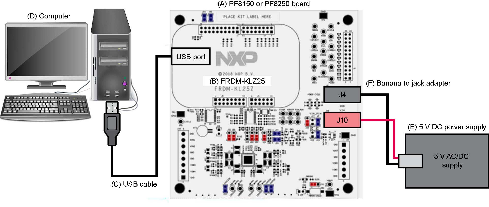
Follow the steps to configure the hardware and workstation as illustrated.
-
With the USB cable connected to the PC and the USB port in the FRDM board, apply the voltage input (VIN) to the evaluation board
- Provide external VIN between 2.5 V to 5.5 V on
J10(VIN) andJ4ground (GND) -
Use the short jumper
J17to provide 3V3 VIN from FRDM board (use this mode of operation for functional demonstration only, no regulation loading is allowed in this mode)
- Provide external VIN between 2.5 V to 5.5 V on
- Press reset the FRDM board to ensure that the board is properly recognized
4. Install Software
4.1 Downloading the GUI
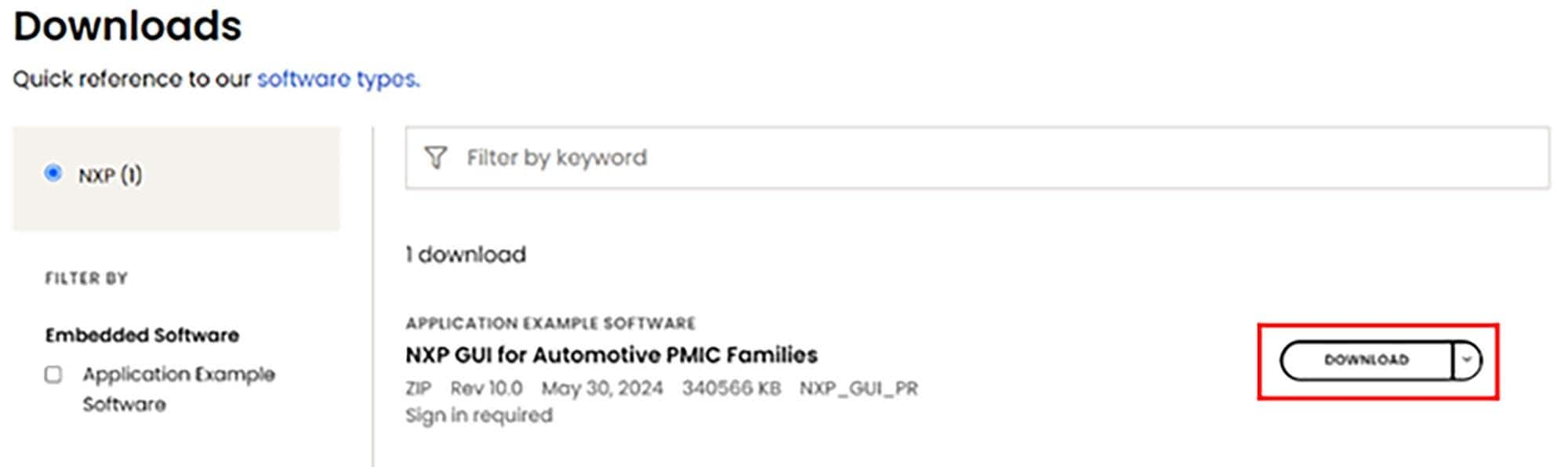
- Sign in to the NXP website and click the button to download the NXP GUI for Automotive PMIC Families. This GUI interface integrates multiple products of the NXP Auto PMICs. You will need to read the agreement and accept to download the files.
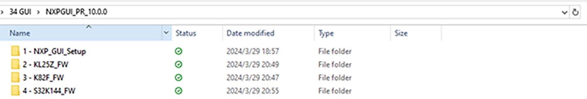
- Go to the folder location in which the GUI package is saved, unzip the files and open them (as shown below)
4.2 Installing and Opening GUI
- Open the "
1-NXP_GUI_Setup" folder and click the file named "NXP_GUI-10.0.0-Setup.exe", to install the GUI -
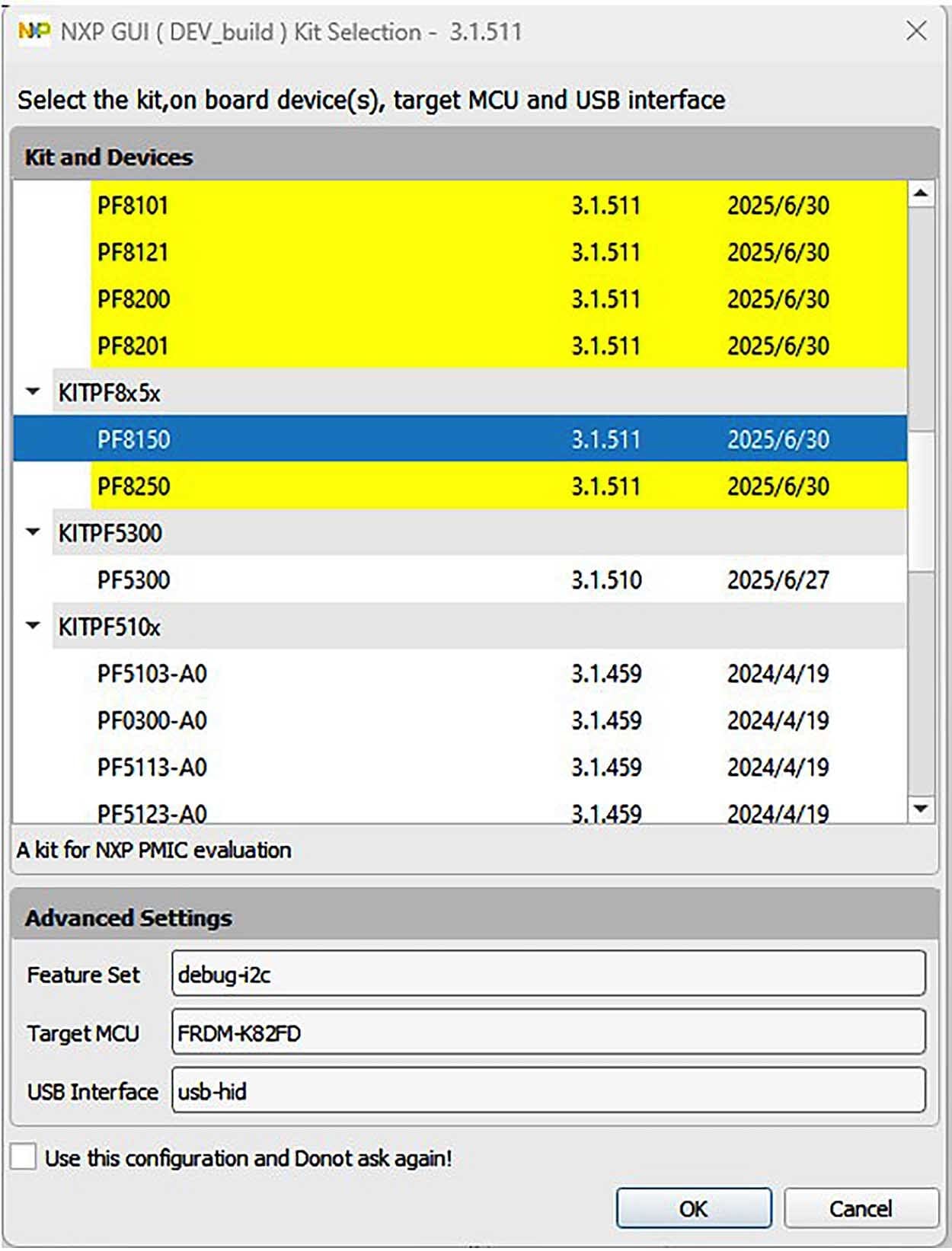
When opening the GUI, select the PMIC product on the evaluation board as shown below (e.g. if the evaluation board is KITPF8150FRDMEVM, select PF8150 and click OK)
4.3 Updating the PF8150/PF8250 Firmware
The FRDM-KL25Z board is used as a communication bridge to interface the GUI with the PMIC and other I²C devices. The firmware is organized in three levels:
- At first level, the serial and debug adapter (SDA) uses the bootloader—preprogrammed and cannot be reflashed to protect the board—to operate as the main path to flash the functional code of the SDA processor
- At the second level, the SDA provides a firmware loader for a drag and drop update of the KL25Z MCU firmware
- At the third level, the KL25Z MCU provides the GUI firmware for converting the USB communication into MCU instructions to control digital I/Os as well as I²C communication to the PMIC
If the FRDM-KL25Z is not loaded with the correct firmware to allow a future software upgrade, the firmware can instead be updated in a few simple steps as outlined below.
Flashing the FRDM-KL25Z Firmware Loader
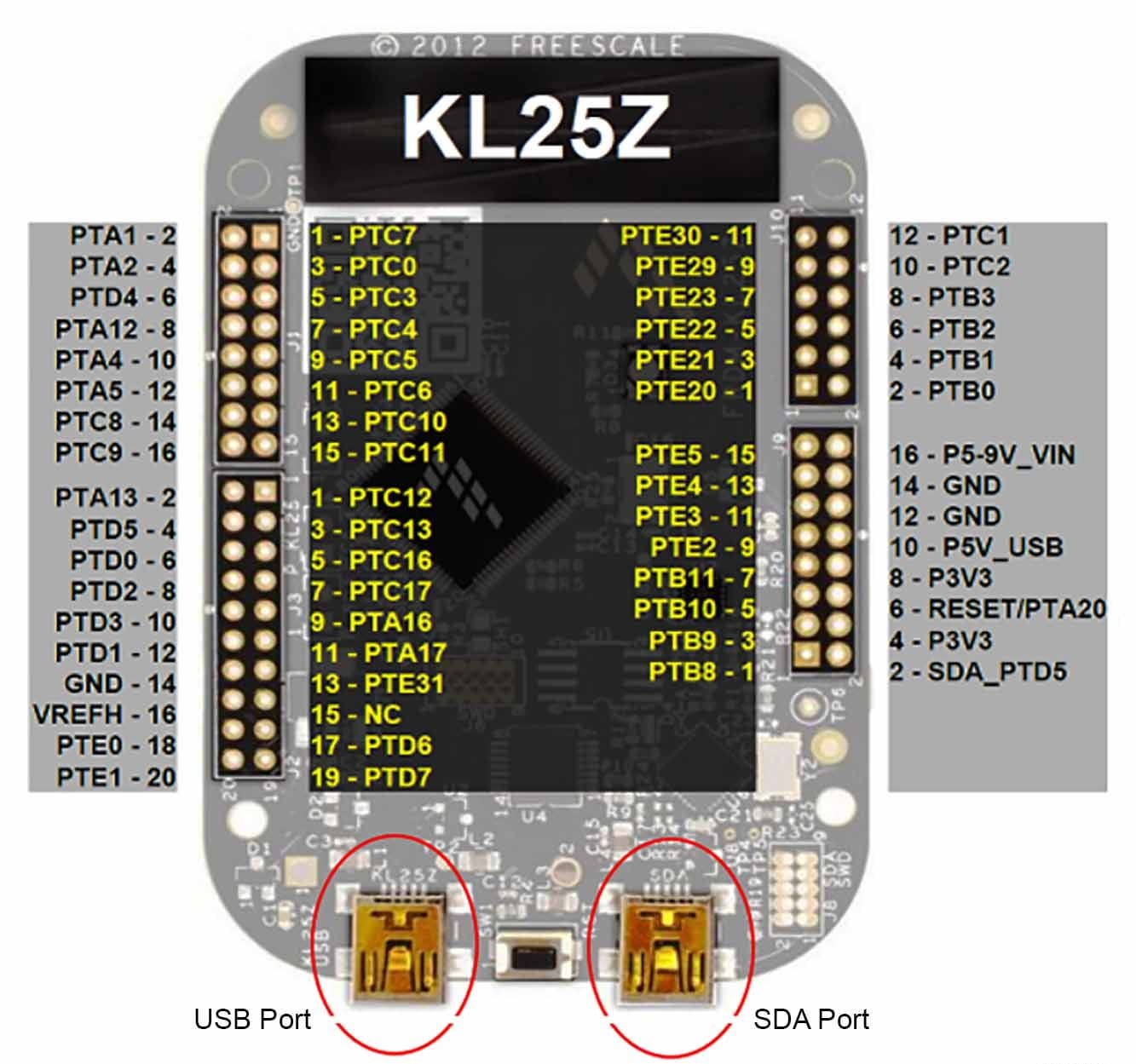
- Press the push button to connect the USB cable to the SDA port on the FRDM board, then a new bootloader device should appear on the left pane of the file explorer
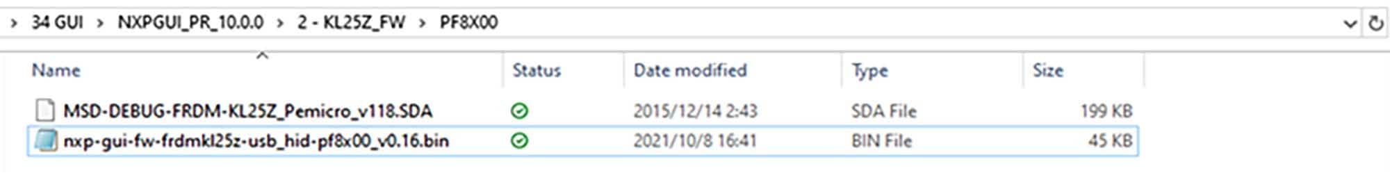
- Drag the file
MSD-DEBUG-FRDM-KL25Z_Pemicro_v118.SDA(located in the KL25Z_FW folder) into the bootloader drive - Next, you will install a new device (
FRDM_KL25Z) by disconnecting and reconnecting the USB cable into the SDA port (this time without pressing the push button)

Flashing the GUI Firmware
If a new software or silicon release requires a firmware update on the FRDM-KL25Z freedom board, use the following procedure to upgrade or downgrade the firmware of the freedom board as needed. Note that this procedure is needed only to update the firmware and may be skipped if no change is needed.
- Connect the USB cable in the SDA port (without holding the pushbutton)
- Locate the "
.bin" GUI driver to be installed, (for examplenxp-gui-fw-frdmkl25z-usb_hid-pf8x00_v0.16.bin, drag the file into the FRDM_KL25Z driver) - Freedom board firmware will now be successfully loaded
Design Resources
Board Documents
Software
Additional References
In addition to PF81-PF82, visit:
Product Pages
- i.MX8X: i.MX 8X Family - Arm® Cortex®-A35, 3D Graphics, 4K Video, DSP, Error Correcting Code on DDR
- S32V234: Vision Processor for Front and Surround View Camera, Machine Learning, and Sensor Fusion
Hardware Pages
Application Pages Automotive
- Automotive Sensor Fusion Systems
- Automotive Vision Systems
- Entry Infotainment/Connected Radio
- Front View Camera
- Gateway
- Intelligent Roadside Unit
- Mid/High-End Infotainment Head Unit
- Surround View and Sense Park Assist System Industrial
- Vision, Advanced Sensing, and Processing Board Networking
- Small Business Router
Support
Forums
Connect with other engineers and get expert advice on designing with the KITPF8X50FRDMEVM evaluation board using our community sites.