Wireless MCU Kit Quick Setup Guide
Contents of this document
-
Plug It In
-
Get Software
-
Build, Run
-
Modify an SDK Example
Sign in to save your progress. Don't have an account? Create one.
Purchase your KW45B41Z Evaluation Kit with Bluetooth® Low Energy
1. Plug It In
Let's take your KW45B41Z board for a test drive! You have the choice of watching the sequence in a short video or following the detailed actions listed below.
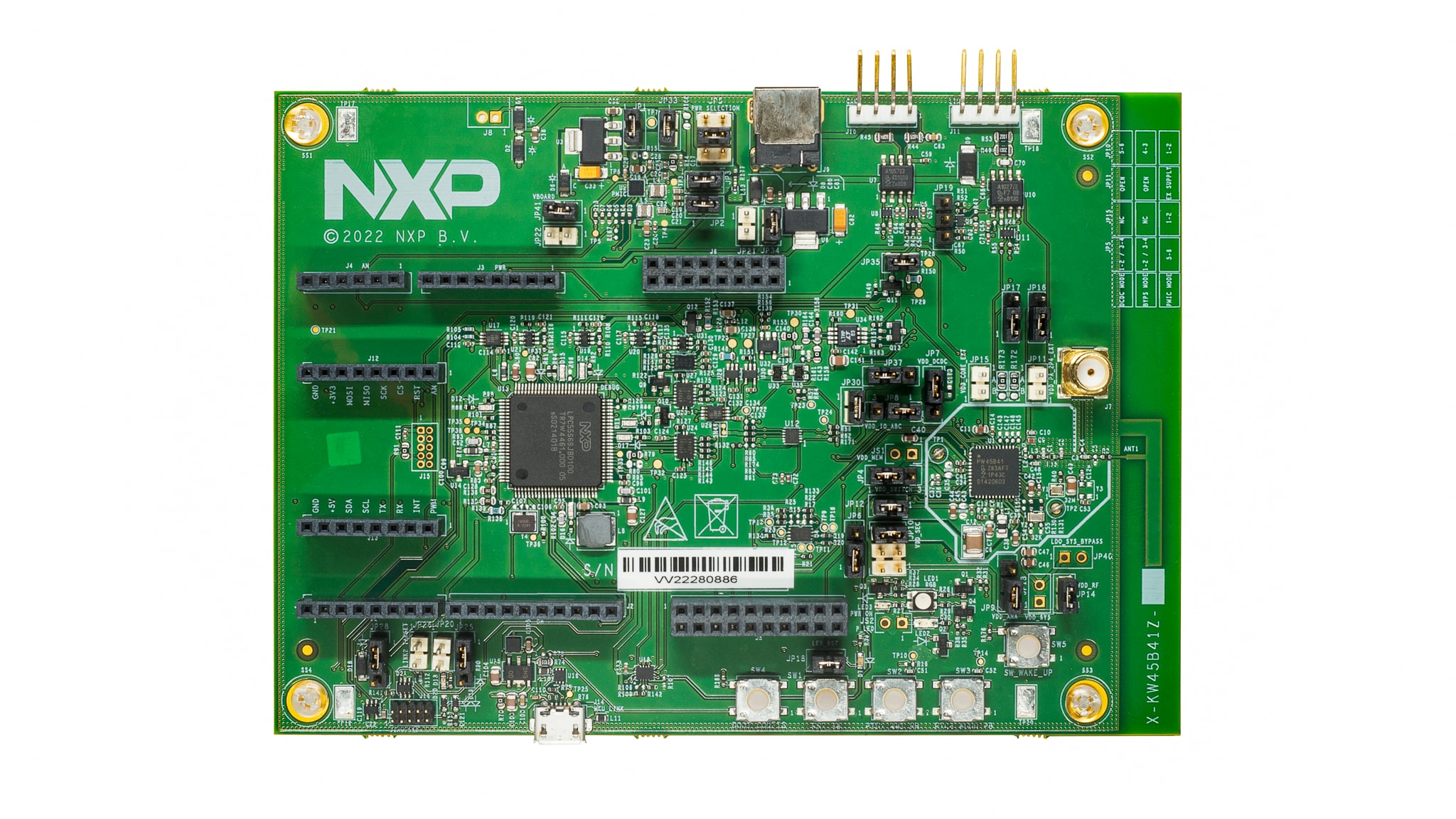
1.1 Get Familiar with the Board
The KW45B41Z board is pre-programmed with a diagnostic demo, which tests various features of the board. This program utilizes the MCU-LINK VCOM output, which is connected to the debug probe(J14), which acts a serial to USB bridge to a host computer, as well as providing the CMSIS-DAP debug interface.
1.2 Serial Terminal
Most of the MCUXpresso SDK examples and this out-of-box demo set up for MCUXpresso IDE, IAR and Keil tools use the MCU UART for print output. If you are not sure how to use a terminal application try one of these: MCUXpresso Terminal Tutorial, Tera Term Tutorial, PuTTY Tutorial.
1.3 Plug In the Board
Connect a micro USB cable from connector J14 to a host computer or power supply to power up the board and run the demo program. The demo can be tested with any Bluetooth® Smart Ready products available on the market. The IoT Toolbox can also be used to showcase the profile functionality. For the out-of-the box experience please download the IoT Toolbox on your smartphone from your device's APP store.
1.4 Run the Out-of-Box Demo
Get familiar with the beacons by selecting the 'Beacons' icon once you have opened the IoT Toolbox App.
The beacons are non-connectable advertising packets that are sent on the three advertising channels. The latter contains the following fields.
- Company Identifier (2 bytes): 0x0025 (NXP ID as defined by the Bluetooth SIG)
- Beacon Identifier (1 byte): 0xBC (Allows identifying an NXP Beacon alongside with Company Identifier)
- UUID (16 bytes): Beacon sensor unique identifier
- A (2 bytes): Beacon application data
- B (2 bytes): Beacon application data
- C (2 bytes): Beacon application data
- RSSI at 1m (1 byte): Allows distance-based applications
2. Get Software
2.1 Install Your Toolchain
NXP offers a complimentary toolchain called MCUXpresso IDE. Please download MCUXpresso v11.6.0 or above.

Want to use a different toolchain?
No problem! The MCUXpresso SDK includes support for other tools such as IAR .

2.2 Jump Start Your Design with the MCUXpresso SDK
The MCUXpresso SDK is complimentary and includes full source code under a permissive open-source license for all hardware abstraction and peripheral driver software.
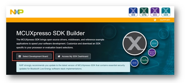
You may install the MCUXpresso SDK directly form the MCUXpresso SDK website at mcuxpresso.nxp.com. Click on “Select Development Board” to search for the evaluation board.
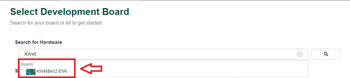
In the Search for Hardware search box, type in the selected board “KW45B41Z-EVK”. Click on the board to select it.
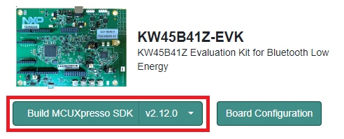
On the right hand side you will see the option to build the SDK for the KW45B41Z-EVK. Click on this button to add the middleware needed.
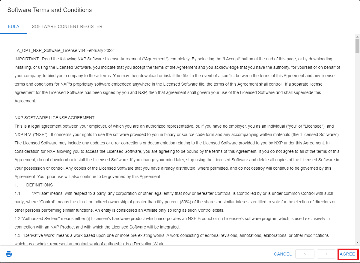
To build the SDK, let's “Select All” for the middleware available. Then scroll down and press “Download SDK”. The Software Terms and Conditions will appear, select “I Agree” in order to begin the download.
Once the SDK package has been downloaded, drag and drop to the “Installed SDKs” window in the MCUXpresso IDE.
If you are using another toolchain, you can download the SDK release for the KW45B41Z-EVK using the link below.

2.3 MCUXpresso Config Tools
The MCUXpresso Config Tool is an integrated suite of configuration tools that guides users in creating new MCUXpresso SDK projects, and also provides pin and clock tools to generate initialization C code for custom board support. It is fully integrated as a part of MCUXpresso IDE and also as a separate tool if using a different IDE.
Click the Get MCUXpresso Config Tools below to get the Config Tools installer.

2.4 Install Drivers
MCU-Link is supported on host computers running on Windows 10, MacOS X, and Ubuntu Linux operating systems (OSs). For each OS, an MCU-Link firmware package is available that includes the host device drivers, MCU-Link firmware, and scripts to program CMSIS-DAP and J-Link firmware options.
To download and install the host device drivers and update the MCU-Link firmware, follow these steps:
- Go to the MCU-Link page on the NXP website
- Click Design Resources. Then, click the SOFTWARE category. The latest version installation packages are displayed at the top for all three compatible OSs
- Download the package for your host OS and install it (Linux/MacOS) or execute the installer program (Windows). The package is installed/unzipped to the
MCU-LINK_installer_Vx_xxxdirectory - Switch MCU-Link to (USB) ISP mode by shorting jumper
JP20 - Connect the
J14connector on the board to the USB port of the host computer through a USB micro-B cable. MCU-Link gets powered up in (USB) ISP mode. The board gets enumerated as a human interface device (HID) class device - Program the MCU-Link firmware into the MCU-Link internal flash using the instructions provided in the "Firmware Installation Guide" section of the "Readme.txt" file. This file can be found in the
MCU-LINK_installer_Vx_xxx_directory. Use the scripts provided to program the CMSIS-DAP or J-Link firmware option - Disconnect the board from the host computer, remove jumper
JP20and reconnect the board
2.5 Programming and Provisioning Tools
The MCUXpresso Secure Provisioning (SEC) Tool is a GUI-based application provided to simplify the generation and provisioning of bootable executables on NXP MCU devices. We recommend all users to begin with the MCUXpresso Secure Provisioning (SEC) tool for trial run and mass production use. It supports secure programming and device provisioning on NXP's microcontrollers at the production stage.
After downloading the tool, you can find the user guide under the ‘Help’ tab. Follow the instructions for your board in the ‘Processor-specific workflow’ chapter.

Note: For advanced users that need a more customizable set-up we also offer a command-line tool that is useful when interfacing with a custom or partner programming tool. The Secure Provisioning SDK (SPSDK) is an open source development kit with its source code released on GitHub and PyPI.
3. Build, Run
The KW45B41Z Wireless Connectivity software comes with a list of demo applications and driver examples ready to be compiled and run for each connectivity stack.
A short video is provided to walk you through this process or you can follow along the steps below.
3.1 Explore the MCUXpresso SDK Example Code
The MCUXpresso SDK comes with a long list of example applications code. To see what's available, browse to the SDK boards folder of your SDK installation and select KW45B41Z ( <SDK_Install_Directory>/boards/KW45B41Z ).
To learn more about specific example code, open the readme.txt file in an example's directory.
3.2 Building and Debugging MCUXpresso SDK Examples
If one or more of the demo applications or driver examples sounds interesting, you're probably wanting to know how you can build and debug yourself. The Getting Started with MCUXpresso SDK guide provides easy, step-by-step instructions on how to configure, build and debug demos for all toolchains supported by the SDK.
Use the guide below to learn how to open, build and debug an example application using the MCUXpresso IDE.
Building and Running a DSP Demo
The KW45B41Z SDK provides a collection of example applications.
Build and Flash Cortex-M33 Application
The following steps will guide you through the hello_world demo application using MCUXpresso IDE for the Cortex-M33 application. The MCUXpresso IDE installation can be found at the section “2. Get Software” of this Getting Started guide.
- Open the MCUXpresso IDE
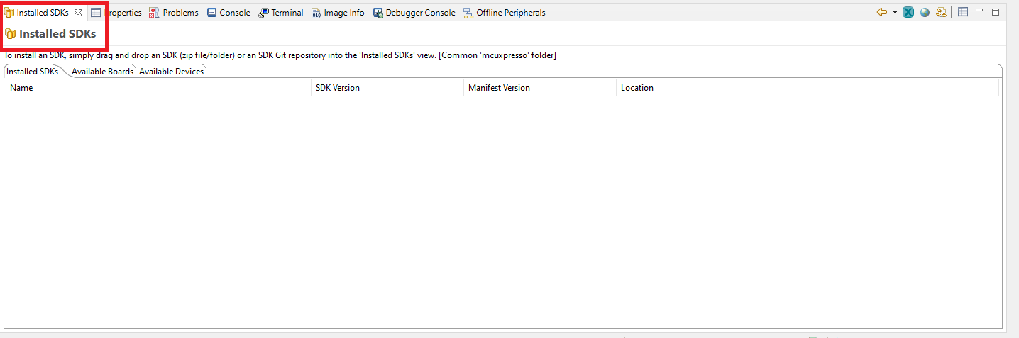
- Switch to the Installed SDKs view within the MCUXpresso IDE window
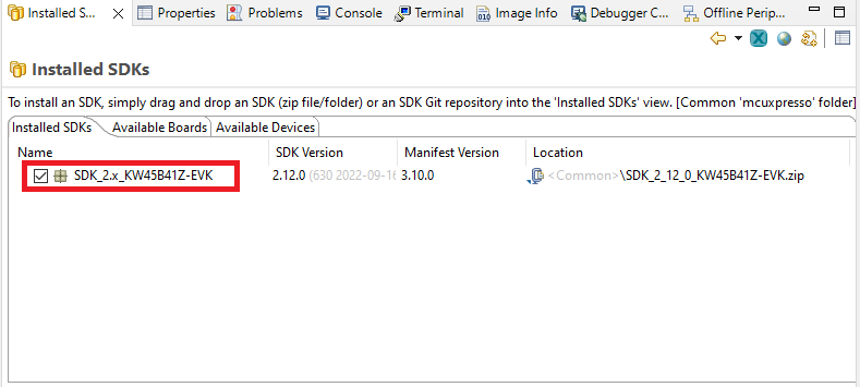
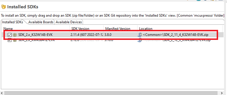
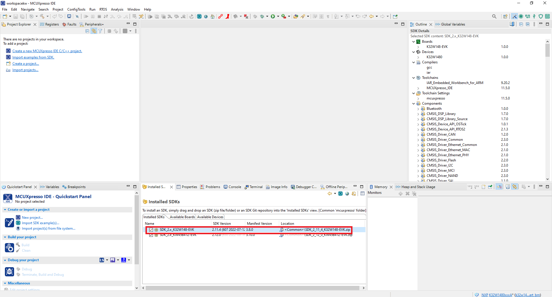
- Drag and drop the KW45B41Z SDK (zipped) file into the Installed SDKs view
- The installed SDK will appear in the Installed SDKs view as shown below:
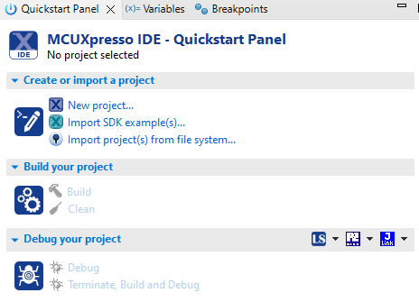
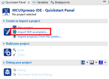
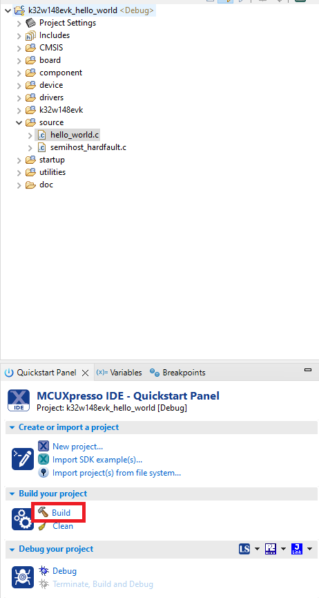
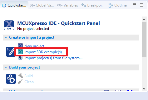
- Find the Quickstart Panel in the lower left-hand corner
- Then click on Import SDK example(s)…
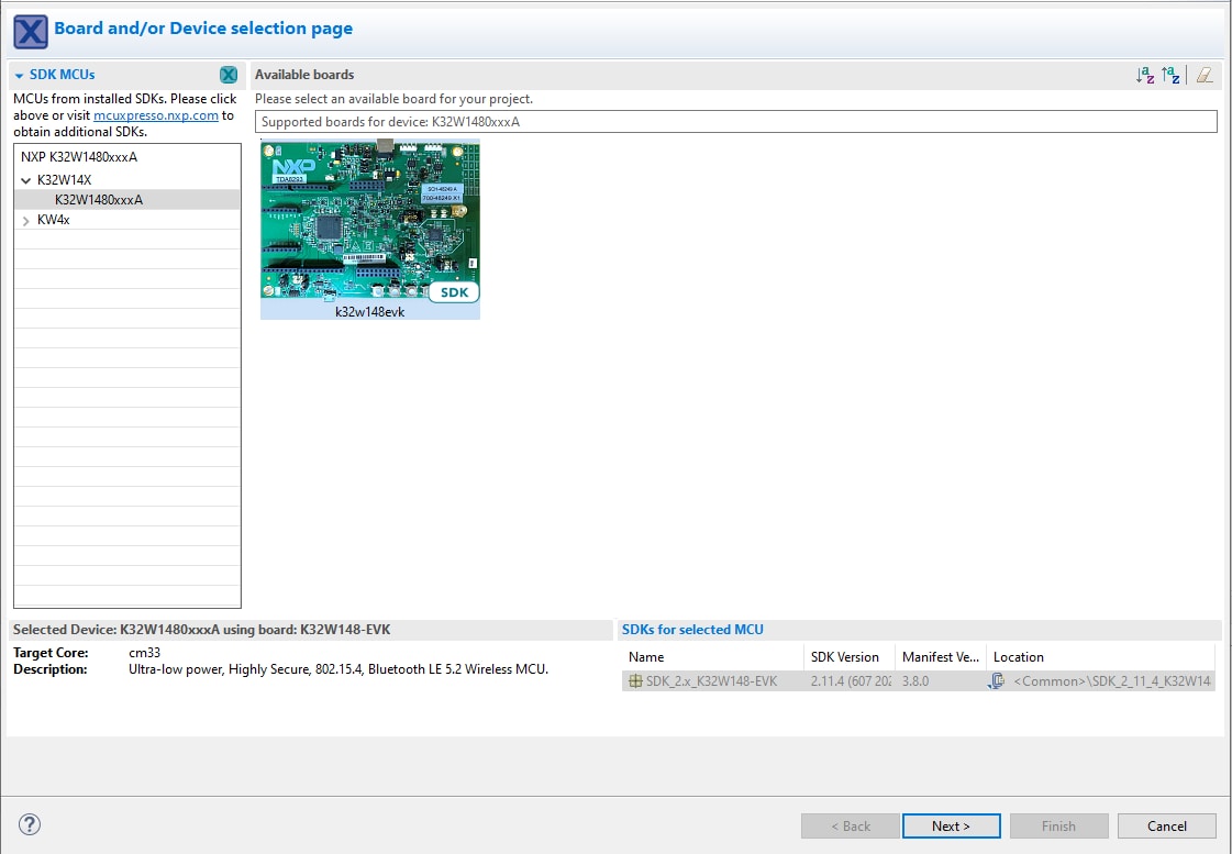
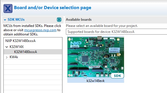
- Click on the KW45B41Z-EVK board to select that you want to import an example that can run on that board and then click on Next
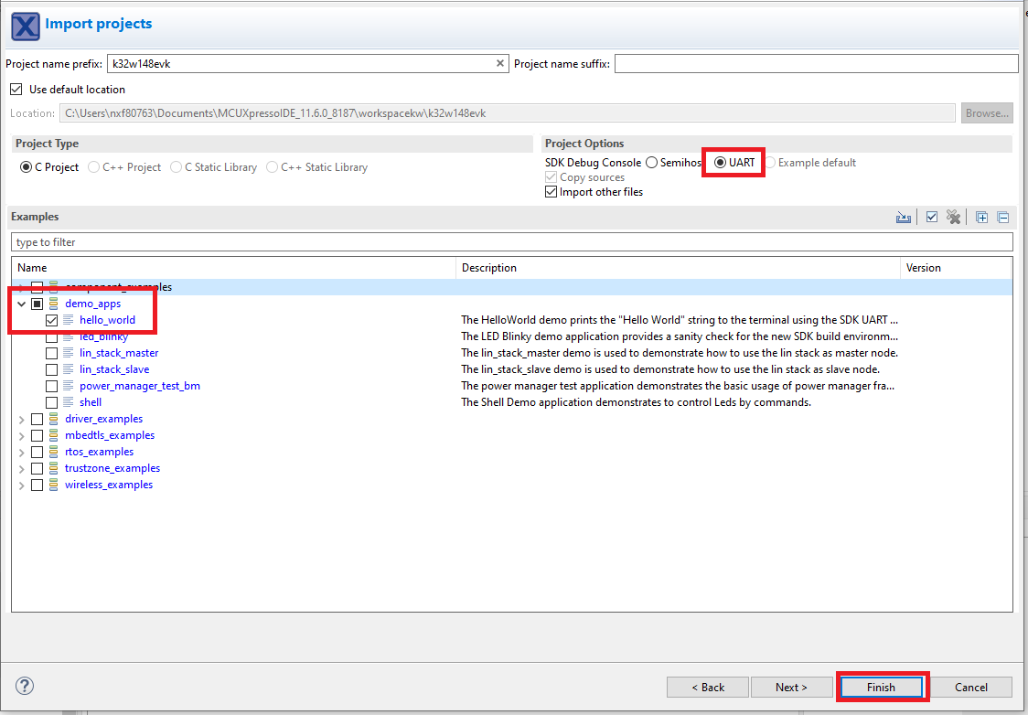
- Use the arrow button to expand the demo_apps category and then click the checkbox next to hello_world to select that project. To use the UART for printing (instead of the default semihosting), select UART as the SDK Debug Console checkbox under the project options. Then, click on Finish
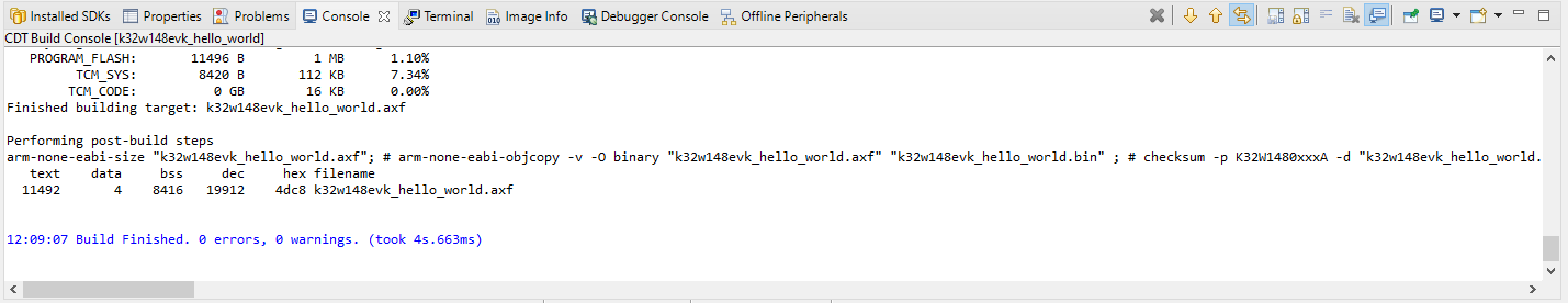
- Select the project and build it
- The project will build without problems
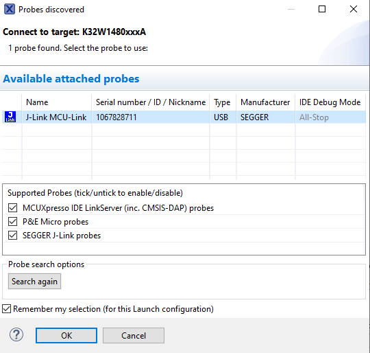
- Connect the board to your computer with the micro USB to
J14'LINK USB' port - Download the application to your KW45B41Z-EVK
- Select the J-Link debug probe
- Run the application

Using a different toolchain?
This demo is also available for IAR.
Running a demo using IAR Embedded Workbench IDE
Build an Example Application
The following steps will guide you through opening the hello_world application. This application consists of code for both the Cortex M33 and the DSP core. The instructions for compiling and debugging the Cortex M33 core are covered in the instructions below.
Instructions for compiling and debugging the DSP code can be found in Section 2 of the “Use MCUXpresso IDE” tutorial. These steps may change slightly for other example applications as some of these applications may have additional layers of folders in their path.
Please use IAR Embedded Workbench for Arm version 9.10 or above.
- First, unzip the previously downloaded KW45B41Z SDK package.
- Open the desired example application workspace. Most example application workspace files can be located using the following path:
- Select the desired build target from the drop-down. For this example, select the “
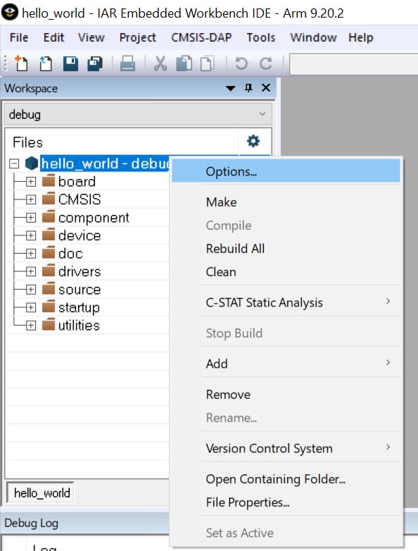
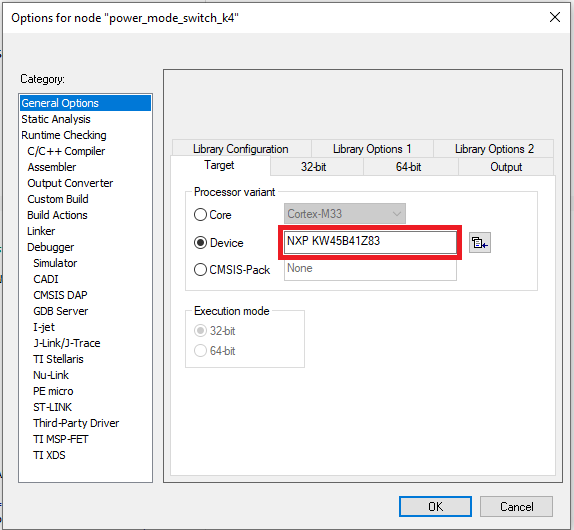
hello_world - Debug” target - Open the project properties by doing a right-click on the project and selecting Options.
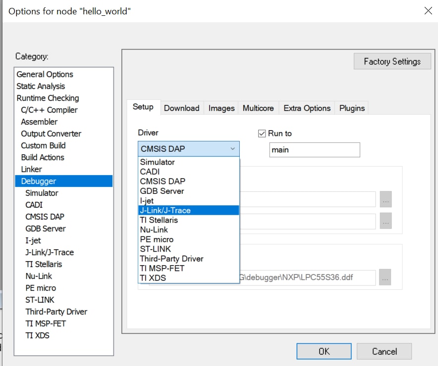
- Now go to the Debugger section and change the debugger driver to Jlink. Press the OK button.
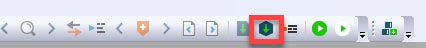
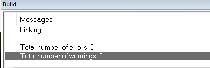
- To build the application, click the “Make” button, highlighted in red below.
- The build will complete without errors.
<install_dir>/boards/<sdk_board_name>/<example_type>/<application_name>/iar Using the mu_polling demo as an example, the path is:
<install_dir>/boards/KW45B41Z/dsp_examples/hello_world/cm33/iar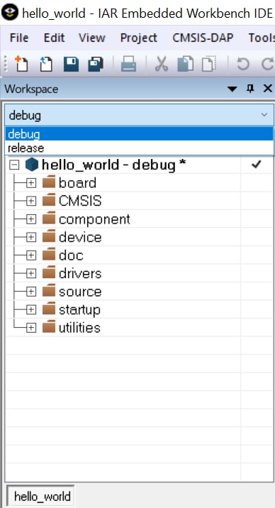
Run an Example Application
- Connect the development platform to your PC via USB cable to
J14“Link USB” - Click the "Download and Debug" button to download the application to the target
- The application is then downloaded to the target and automatically runs to the
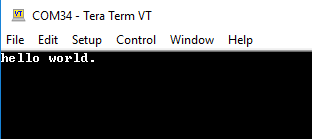
main()function - Run the code by clicking the "Go" button to start the application
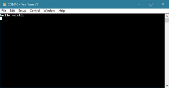
- The
hello_worldapplication is now running on the Cortex-M33

To build and debug the code for the DSP part of this application, open the “Use MCUXpresso IDE” tutorial and follow the instructions starting at “2. Build and Debug the DSP Application”.
3.3 Updating NBU for Wireless Examples
Alert code:
It is necessary to work with the matching NBU image for the SDK version of the application you are
working with. This means that when you download your SDK, prior to loading any wireless SDK example,
update your NBU image with the provided binaries in the following folder of the SDK:
../middleware/wireless/ble-controller/bin.
This feature is available only for processors with radio. The NBU firmware is distributed within the MCUXpresso.
SDK as an .sb3 file or as a binary file (*.xip), in folder
middleware\wireless\ble_controller\bin\.
There are two options to update the NBU firmware. First, use a prepared SB file with NBU firmware. It can be
used for the EVK and FRDM boards with provisioned NXP keys. The other way is to prepare a custom SB file
that will load the NBU firmware.
SB file with NXP keys on EVK
- Create or open a workspace for
KW45xx/K32W1xx/MCXW71xx/KW47xx/MCXW72xx - In the menu bar, select Tools > Manufacturing Tool
- Select the Apply SB file operation
- Provide the SB file
- Detect a connected device by clicking the Auto detect button
- Load the SB file by clicking the Start button
Custom SB file
- Open a workspace for
KW45xx/K32W1xx/MCXW71xx/KW47xx/MCXW72xxwith the custom keys that were provisioned to the device - Copy NBU firmware into workspace as
source_images\nbu_firmware.xip - In the menu bar, select Tools > SB Editor
- Fill the Properties tab or import a setting from the SB file created on the Build tab
- Switch to the Commands tab
- Select High-level command
update-nbu-firmware - Prepare the final SB file by clicking the Generate button
- Click the To Manufacturing tool button to switch to the manufacturing window with preselected Apply SB file operation and preselected SB file
- Detect a connected device by clicking the Auto detect button
- Load the SB file by clicking the Start button
4. Modify an SDK Example
A short video is provided to walk you through this process, or you can follow along the steps below.
4.1 Clone an Example Project from MCUXpresso SDK
Option A: Use the MCUXpresso IDE to import an example project.
Use MCUXpresso IDE
Build an Example Application
The following steps will guide you through the manipulation of the general-purpose outputs. The example it will be a wireless uart.
- Find the Quickstart Panel in the lower left-hand corner
- Then click on Import SDK examples(s)…
- Click on the K32W1 board to select that you want to import an example that can run on that board and then click on Next
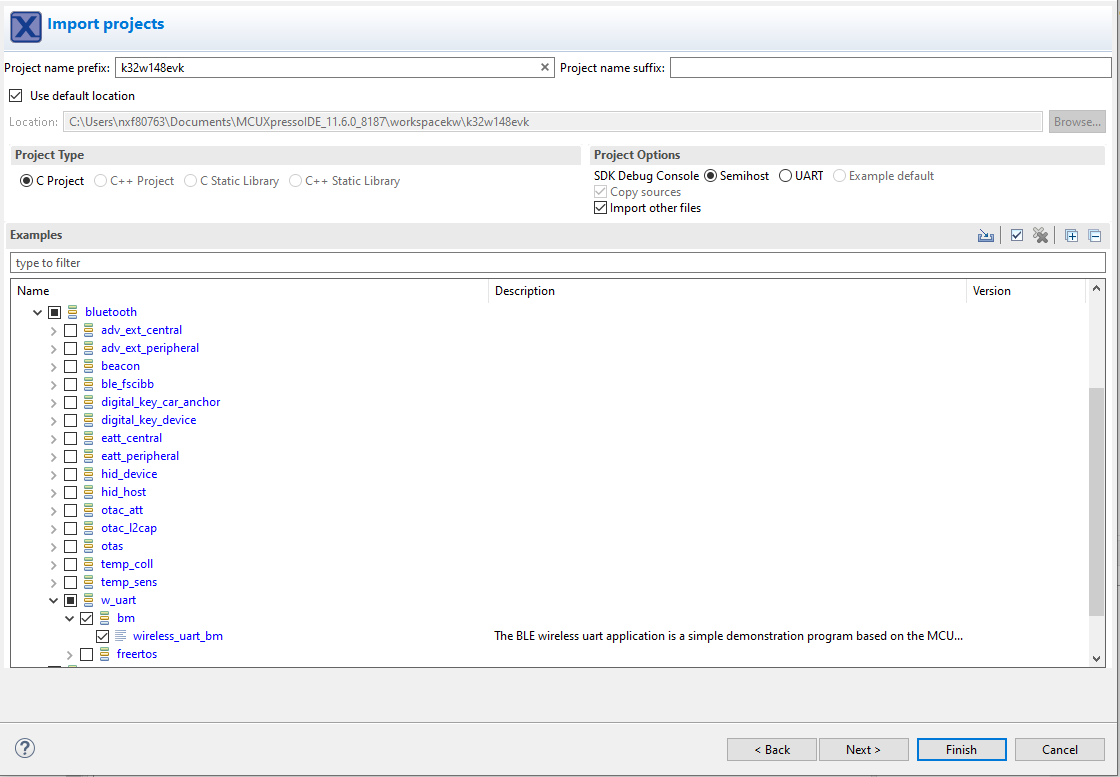
- Use the arrow button to expand the
wireless_examplescategory, then expand thebluetoohexamples, click on the check box next tow_uartto select it. To use the UART for printing (instead of the default semihosting), Select UART as the SDK Debug Console checkbox under the project options. Then, click on Finish - Click on the “
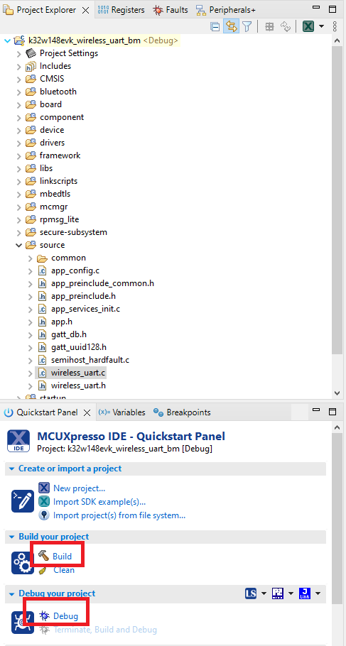
KW45B41Zevk_wireless_uart_bm” project in the Project Explorer View and build, compile and run the demo as described previously - You should be able to connect to the wireless uart using the IoT Tool Box
- Terminate the debug session
Option B: Use the MCUXpresso Config Tool to clone an existing MCUXpresso SDK example for use with third party IDEs.
Use MCUXpresso Config Tools
The following steps will guide you through the manipulation of the general-purpose outputs. The example sets up a Led blinky project and change a LED brightness.
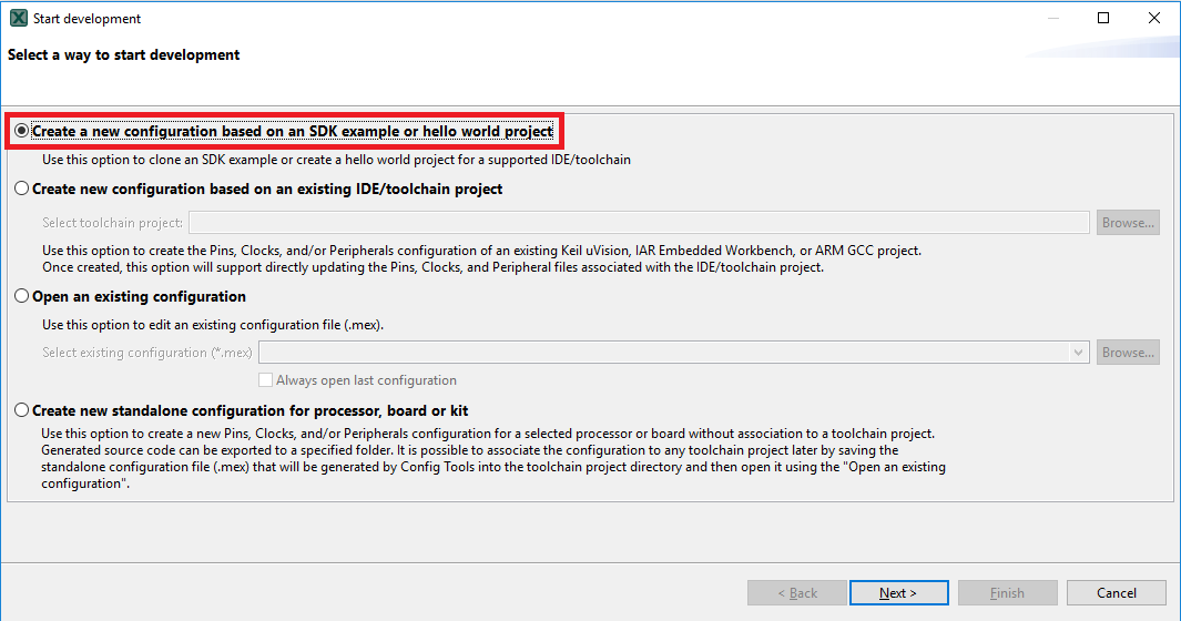
- Open the MCUXpresso Config Tool
- In the wizard that comes up, select the “Create a new configuration based on an SDK example or hello word project” radio button and click on Next
- On the next screen, select the location of the MCUXpresso SDK that you had unzipped earlier. Then select the IDE that is being used. Note that only IDEs that were selected in the online SDK builder when the SDK was built will be available and click on clone select example
- After cloning go to the directory you selected and open the project for your IDE. Import, compile and run the project as done in previous sections
- You should see the GREEN LED changing the brightness
- Terminate the debug session.
Then select the project to clone. For this example, we want to use the gpio led output project. You can filter for this by typing “led” in the filter box and then selecting the “led_blinky” example project. You can then also specify where to clone the project and the name. Then click on Finish.

4.2 Use the Pin Tool
Now, let's use the Pins tool that is part of the MCUXpresso Config Tool to show how to add a new GPIO pin to your project to blink an LED.
Use MCUXpresso IDE Pins Tools
- To open pin tools in MCUXpresso IDE:
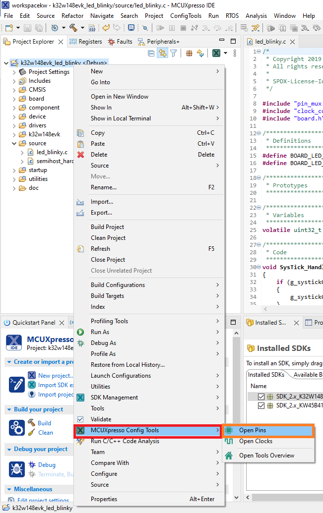
- Open the pins tool by right clicking on the “KW45B41Zevk_led_blinky” project and selecting “MCUXpresso Config Tools” and then “Open Pins”
- The pins tool should now display the pin configuration for the led blinky project
- To open pin tools in MCUXpresso Config tools:
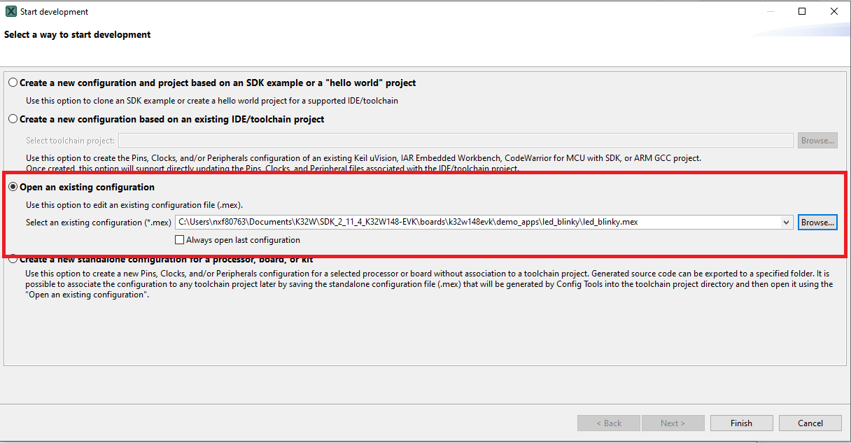
- Open the MCUXpresso Config Tool
- In the wizard that comes up, select the “Open existing configuration” radio button, then select the project that you had clone and click on Next
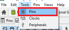
- Open the pins tool by selecting Tools → Pins from the toolbar
- The pins tool should now display the pin configuration for the led blinky project
- Use the pins tools to modify the GPIO routed pin:
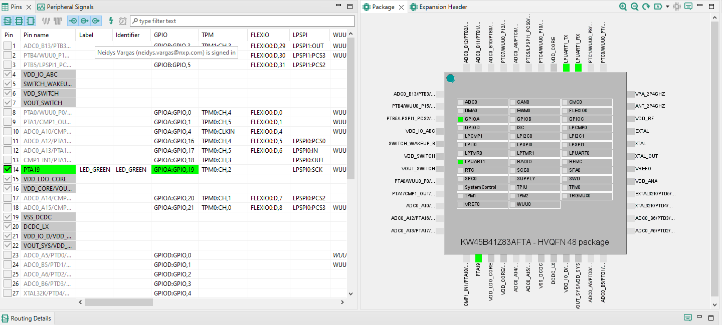
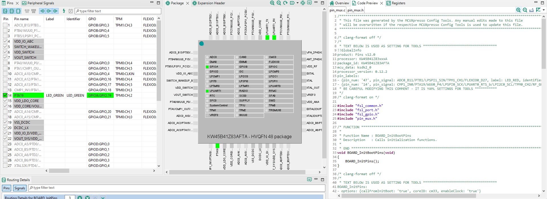
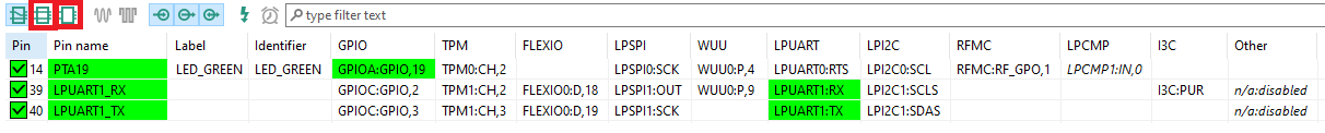
- We'll use MCUXpresso IDE for the rest of the instructions, but the same steps can be done in MCUXpresso Config tools for third party IDEs. In the Pins view deselect “Show dedicated pins” and “Show no routed pins” checkboxes to see only the routed pins. Routed pins have a check in a green box next to the pin name. The functions selected for each routed pin are highlighted in green
- In the current configuration, GPIOA is routed as a PTA19. Let's disable, PTA19 and change the mux setting of PTA21 to use its functionality
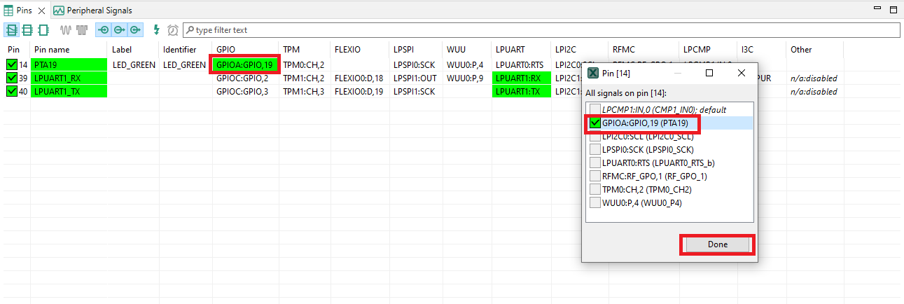
- 4. Disable PTA19 by clicking the “GPIOA” field under the GPIO column. A new window will appear. Deselect the GPIOA checkbox and click on Done. The pin will then be disabled (pin will no longer have check in box) and thus disappear from the list
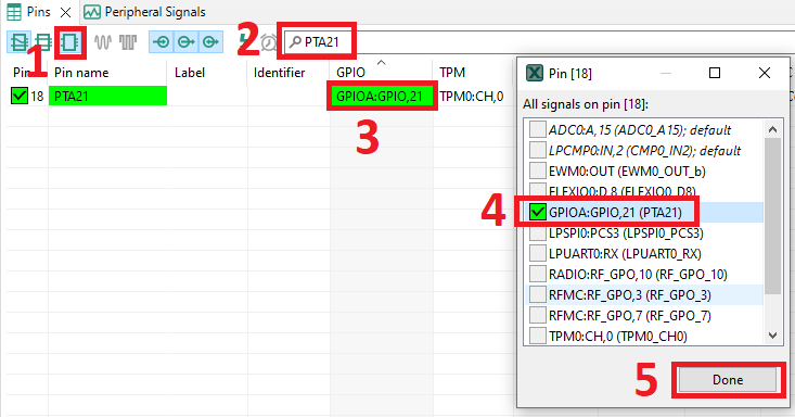
- Now, route GPIOA as a PTA21. First, select the “Show not routed pins” so that all the pins are displayed again. Then, search PTA21 in the pins view. Finally, click the box under the GPIO column “GPIAO21”. The box will highlight in green and a check will appear next to the pin
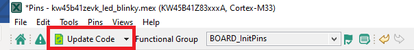
- Now it's time to implement these changes into the project by exporting the new updated
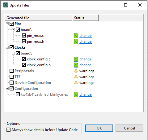
pin_mux.candpin_mux.hfiles that are generated by the Pins tool. Click on Update Project in the menu bar - The screen that pops up will show the files that are changing and you can click on “diff” to see the difference between the current file and the new file generated by the Pins tool. Click on “OK” to overwrite the new files into your project
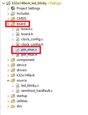
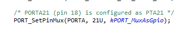
- Now inside the IDE, open the
pin_mux.cfile under board folder - Search for BOARD_InitPins(void) function. Note that when we change the sct routed pin in the tool the GPIAO was selected and configured as PTA19 (green led). Now, we have the declaration of GPIOA and configured as PTA21 (red led)
- Build and download the project as done in the previous section
- Run the application. You should now see the RED LED changing the brightness
- Terminate the debug session
MCUXpresso Terminal Tutorial
MCUXpresso Terminal Tutorial
The most recent versions of MCUXpresso IDE count with a terminal emulation application. This tool can be used to display information sent from your NXP development platform's virtual serial port.
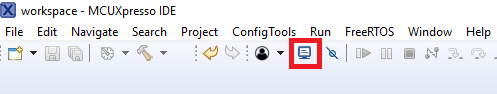
- Open the MCUXpresso IDE

- Launch the MCUXpresso IDE terminal by clicking on the "Open a Terminal" button on the top of the IDE or press "Ctrl + Alt + Shift + T"
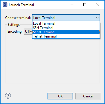
- Select Serial Terminal
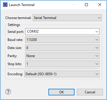
- Configure the serial port settings (using the LPCXpresso COM port number) to 115200 baud rate, 8 data bits, no parity and 1 stop bit, then press "OK" button
- Verify that the connection is open. If connected, MCUXpresso IDE will look like the figure below at the Terminal view
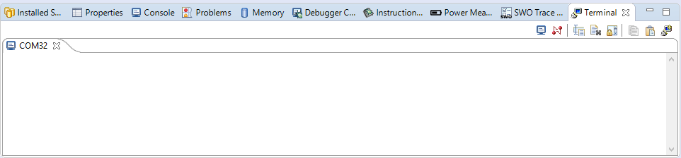
- You're ready to go
Tera Term Tutorial
Tera Term Tutorial
Tera Term is a very popular open source terminal emulation application. This program can be used to display information sent from your NXP development platform's virtual serial port.
- Download Tera Term from SourceForge. After the download, run the installer and then return to this webpage to continue
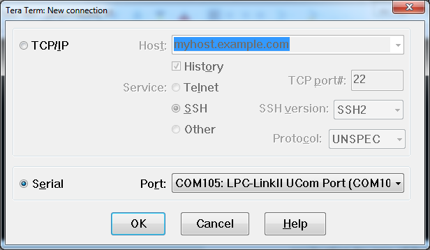
- Launch Tera Term. The first time it launches, it will show you the following dialog. Select the serial option. Assuming your board is plugged in, there should be a COM port automatically populated in the list
- Configure the serial port settings (using the COM port number identified earlier) to 115200 baud rate, 8 data bits, no parity and 1 stop bit. To do this, go to Setup → Serial Port and change the settings
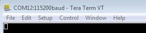
- Verify that the connection is open. If connected, Tera Term will show something like below in its title bar
- You're ready to go
PuTTY Tutorial
PuTTY Tutorial
PuTTY is a popular terminal emulation application. This program can be used to display information sent from your NXP development platform's virtual serial port.
- Download PuTTY using the button below. After the download, run the installer and then return to this webpage to continue
- Launch PuTTY by either double clicking on the *.exe file you downloaded or from the Start menu, depending on the type of download you selected
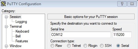
- Configure In the window that launches, select the Serial radio button and enter the COM port number that you determined earlier. Also enter the baud rate, in this case 115200
- Click Open to open the serial connection. Assuming the board is connected and you entered the correct COM port, the terminal window will open. If the configuration is not correct, PuTTY will alert you
- You're ready to go
Design Resources
Board Documents
On this page
- 2.1
Install Your Toolchain
- 2.2
Jump Start Your Design with the MCUXpresso SDK
- 2.3
MCUXpresso Config Tools
- 2.4
Install Drivers
- 2.5
Programming and Provisioning Tools