Getting Started with the LPCXpresso51U68
Contents of this document
-
Plug It In
-
Get Software
-
Build, Run
-
Create
Sign in to save your progress. Don't have an account? Create one.
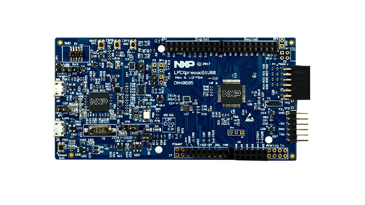
Purchase your LPCXpresso51U68 for the LPC51U68 MCUs
1. Plug It In
1.1 Get Started With the LPCXpresso51U68 Development Board - Demo.
Get started with the LPCXpresso51U68 Development Board – Unpacking and powering up.
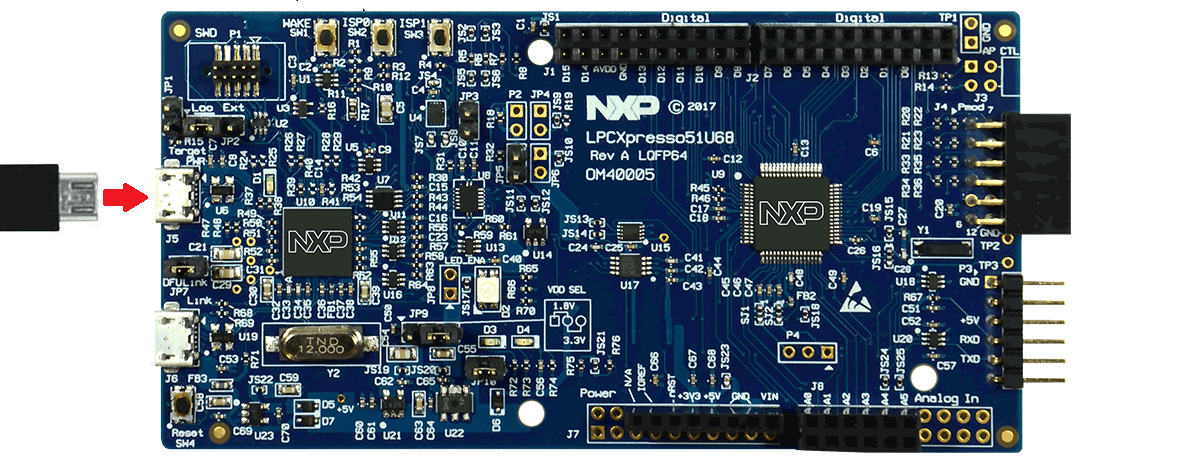
1.2 Attach the USB Cable
1.3 Run the Out-of-Box Demo
Your LPCXpresso51U68 board comes preloaded with a simple program to blink the RGB LED red, approximately every second. The demo will power up and run whenever the board is powered (from either USB connector), but at this stage connect to the power J5 (target) connector.
2. Get Software
2.1 Getting Started With the MCUXpresso SDK
The MCUXpresso Software Development Kit (SDK) is complimentary and includes full source code under a permissive open-source license for all hardware abstraction and peripheral driver software.
Click below to download a pre-configured SDK release for the LPCXpresso51U68, which includes versions for MCUXpresso IDE, Keil MDK and IAR EWARM. Use LPCXpresso51U68 as the target board.

You can also use the online MCUXpresso web tool to create a custom SDK package for the LPCXpresso51U68 using the SDK builder.
2.2 Install your Toolchain
To set up your LPCXpresso51U68 for use with 3rd party tools, first install LPCScrypt in order to install the board’s device drivers.

Want to use a different toolchain? No problem! The MCUXpresso SDK includes support for other tools such as IAR and Keil.

To set up your LPCXpresso51U68 for use with 3rd party tools, first install LPCScrypt in order to install the board’s device drivers. The video below shows how to use LPCScrypt to program your board’s debug probe using this utility.
2.3 MCUXpresso Config Tools
The MCUXpresso Config Tool is an integrated suite of configuration tools that guides users in creating new MCUXpresso SDK projects, and provides pin and clock tools to generate initialization C code for custom board support.

2.4 Serial Terminal
Not sure how to use a terminal application? Try one of these tutorials: Tera Term Tutorial, PuTTY Tutorial.
3. Build, Run
3.1 Explore the MCUXpresso SDK Example Code
The MCUXpresso SDK comes with a long list of example applications code. To see what's available, browse to the SDK boards folder of your SDK installation and select LPCXpresso51U68.
<sdk_install_directory>/boards/LPCXpresso51U68</sdk_install_directory>To learn more about specific example code, open the readme.txt file in an example’s directory.
3.2 Build, Run
If one or more of the demo application or driver examples sounds interesting, you're probably wanting to know how you can build and debug yourself. The Getting Started with SDK for LPC51U68 guide provides easy, step-by-step instructions on how to configure, build, and debug demos for all toolchains supported by the SDK.
Use the guide below to learn how to open, build and debug an example application using the MCUXpresso IDE.
Using a different toolchain?
Use IAR
Build an Example Application
The following steps will guide you through opening the led_output application. These steps may change slightly for other example applications as some of these applications may have additional layers of folders in their path.
-
If not already done, open the desired example application workspace. Most example application workspace files can be located using the following path:
<install_dir>/boards/<sdk_board_name>/<example_type>/<application_name>/iar</application_name></example_type></sdk_board_name></install_dir >Using the hello_world demo as an example, the path is:
<install_dir>/boards/LPCXpresso51U68/driver_examples/gpio/led_output/iar</install_dir> -
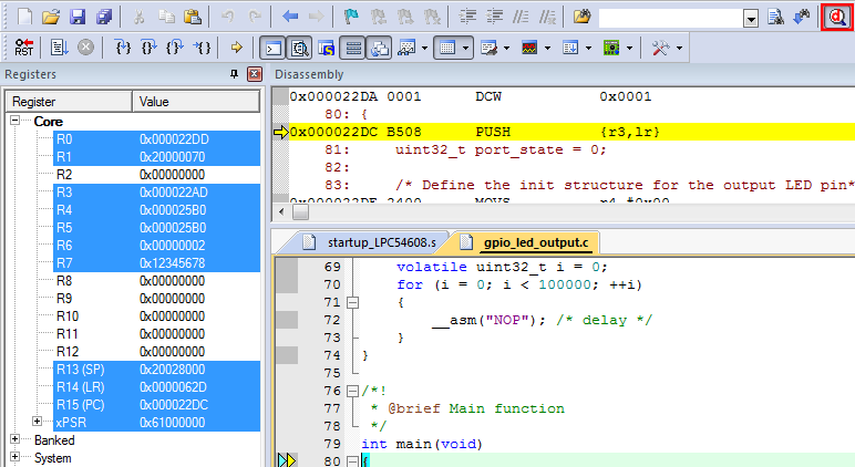
Select the “gpio_led_output – Debug” target.
-
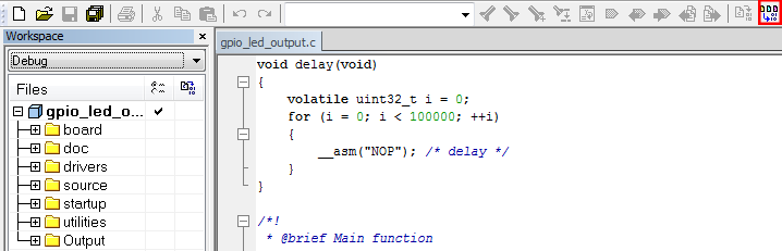
To build the application, click the “Make” button, highlighted in red below.
-
The build will complete without errors.:
Run an Example Application
The LPCXpresso51U68 board comes loaded with the CMSIS-DAP debug interface from the factory. Connect the development platform to your PC via USB cable to J6 “Debug Link”.
Ensure the DFULink jumper (JP7) is removed when powering the board to boot the debug probe from internal flash.
-
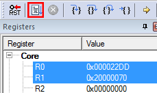
Click the "Download and Debug" button to download the application to the target.

-
The application is then downloaded to the target and automatically runs to the main() function.
-
Run the code by clicking the "Go" button to start the application.

Use Keil® MDK
Install CMSIS Device Pack
After the MDK tools are installed, Cortex® Microcontroller Software Interface Standard (CMSIS) device packs must be installed to fully support the device from a debug perspective. These packs include things such as memory map information, register definitions and flash programming algorithms. Follow these steps to install the appropriate CMSIS pack.
-
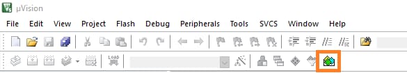
Open the MDK IDE, which is called µVision. In the IDE, select the "Pack Installer" icon.
-
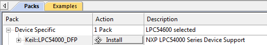
In the Pack Installer window, navigate to the section with the LPC packs (they are in alphabetical order). The LPC packs start with "Keil::LPC" and are followed by the MCU family name; select "Keil::LPC51U00" then LPC51U68 Click on the "Install" button next to the pack. This process requires an internet connection to successfully complete.
After the installation finishes, close the Pack Installer window and return to the µVision IDE.
Build the Example Application
The following steps will guide you through opening the gpio_led_output application. These steps may change slightly for other example applications as some of these applications may have additional layers of folders in their path.
-
If not already done, open the desired demo application workspace in:
<install_dir>/boards/<sdk_board_name>/<example_type>/<application_name>/mdk</application_name></example_type></sdk_board_name></install_dir >The workspace file is named
<application_name>.uvmpw, so for this specific example, the actual path is:</application_name><install_dir>/boards/LPCXpresso51U68/driver_examples/gpio/led_output/mdk/gpio_led_output.uvmpw</install_dir> -
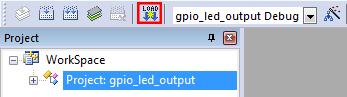
To build the demo project, select the "Rebuild" button, highlighted in red.

The build will complete without errors.
Run an Example Application
The LPCXpresso51U68 board comes loaded with CMSIS-DAP debug interface from the factory.
Ensure the DFULink jumper (JP7) is removed when powering the board to boot the debug probe from internal flash.
- After the application is properly built, click the "Download" button to download the application to the target.
- After clicking the "Download" button, the application downloads to the target and should be running. To debug the application, click the "Start/Stop Debug Session" button, highlighted in red.
- Run the code by clicking the "Run" button to start the application.
4. Create
4.1 Get SDK Project Generator
Let's create our own project and make a simple SDK-based application. NXP provides an intuitive, simple project generation utility that allows creation of custom projects based on the Kinetis SDK.
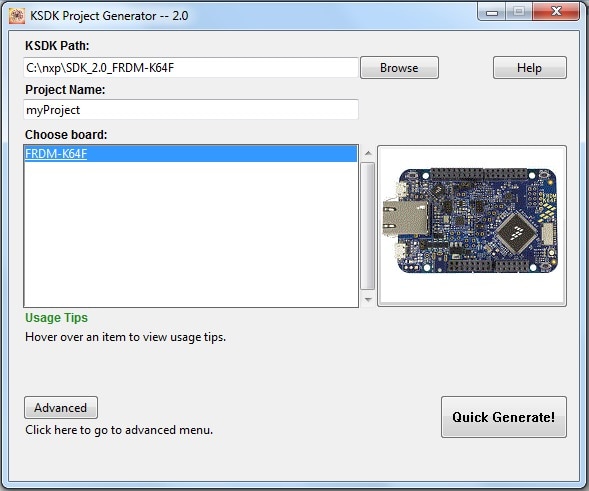
4.2 Run the SDK Project Generator
After extracting the ZIP file, open the utility by clicking on the KSDK_Project_Generator executable for your computer's operating system. Point the tool to your SDK installation path, name your project, and select the board that it uses as a reference. Click on the Quick Generate button to finish.
4.3 Open Your Project
Your new project will be located in.
<sdk_install_directory>/examples/frdmk64/user_apps</sdk_install_directory>Open the project in your toolchain of choice by using the same process described in section 3.2.
4.4 Write Some Code
Now, let's make our new project do something other than spin in an infinite loop. The SDK examples provide a board support package (BSP) to do various things specific to the board, including macros and definitions for items such as LEDs, switches and peripheral instances. To keep things simple, lets make the LED blink using the BSP macros.
Update the main() function in your project's main.c file with the following code:
volatile int delay;
// Configure board specific pin muxing
BOARD_InitPins();

// Configure clock source
BOARD_BootClockRUN();

// Initialize the UART terminal
BOARD_InitDebugConsole();

PRINTF("\r\nRunning the myProject project.\n");

// Enable GPIO port for the red LED
CLOCK_EnableClock(kCLOCK_PortE);
PORT_SetPinMux(BOARD_LED_RED_GPIO_PORT, BOARD_LED_RED_GPIO_PIN, kPORT_MuxAsGpio);
LED_RED_INIT(LOGIC_LED_OFF);
for (;;){
  LED_RED_TOGGLE();
  delay = 5000000;
  while(delay--);
}4.5 Build, Download, Run
With the changes made to your main() function, build your application. Once the build is complete, download the application to your board.
If you need help figuring out how to build, download or run an application, reference your tool-specific guide from section 3.2.
4.6 Success
With the application downloaded, you will see the FRDM-KE15Z's red LED blinking. You can also view terminal output using PRINTF.
Running a Demo Using Kinetis Design Studio IDE
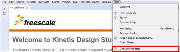
Install KDS Updates
Before using KDS IDE with KSDK, it is recommended that you make sure that your tools are up-to-date. The steps discussed below are shown using the Windows version of KDS, but are identical for Mac and Linux users.
-
Select "Help" → "Check for Updates".
-
Install all updates from Freescale/NXP – these are denoted by
“com.NXP.xxx”or“com.nxp.xxx”. There may also be updates for things such as toolchain or debug interfaces. While these additional updates are typically OK to install, sometimes they may cause issues since they aren’t released as part of the KDS toolchain.
Build an Example Application
The following steps will guide you through opening the hello_world application. These steps may change slightly for other example applications as some of these applications may have additional layers of folders in their path.
-
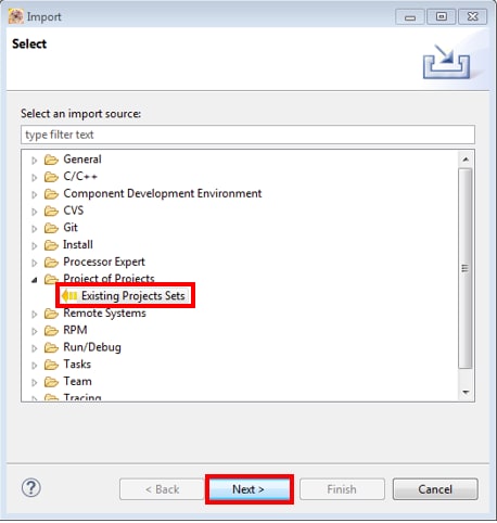
Select File → Import from the KDS IDE menu. In the window that appears, expand the "Project of Projects" folder and select "Existing Project Sets". Then, click the "Next" button.
-
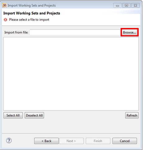
Click the "Browse" button next to the "Import from file:" option.
-
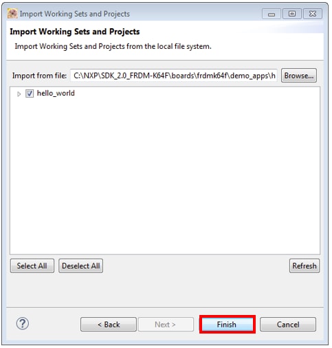
Point to the example application project, which can be found using this path:
<install_dir >/boards/<board_name >/<example_type>/<application_name>/kds</application_name></example_type></board_name ></install_dir >For this guide, choose the specific location:
<install_dir>/boards/frdmke15z/demo_apps/hello_world/kds</install_dir> -
After pointing to the correct directory, your "Import Working Sets and Projects" window should look like the figure below. Click the "Finish" button.
-
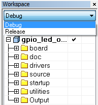
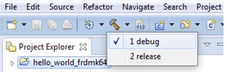
There are two project configurations (build targets) supported for each KSDK project:
- Debug – Compiler optimization is set to low, and debug information is generated for the executable. This target should be selected for development and debug.
- Release – Compiler optimization is set to high, and debug information is not generated. This target should be selected for final application deployment.
-
Choose the appropriate build target, "Debug" or "Release", by clicking the downward facing arrow next to the hammer icon, as shown below. For this example, select the "Debug" target.
-
The library starts building after the build target is selected. To rebuild the library in the future, click the hammer icon (assuming the same build target is chosen).
Run an Example Application
The FRDM-KE15Z board comes loaded with the mbed/CMSIS-DAP debug interface from the factory. If you have changed the debug OpenSDA application on your board, visit OpenSDA for information on updating or restoring your board to the factory state.
Connect the development platform to your PC via USB cable between the "SDAUSB" USB port on the board and the PC USB connector.
-
Open the terminal application on the PC (such as PuTTY or TeraTerm) and connect to the debug COM port you determined earlier. Configure the terminal with these settings:
- 15200 baud rate
- No parity
- 8 data bits
- 1 stop bit
-
For Linux OS users only, run the following commands in your terminal. These install libudev onto your system, which is required by KDS IDE to launch the debugger.
user@ubuntu:~$ sudo apt-get install libudev-dev libudev1user@ubuntu:~$ sudo ln –s /usr/lib/x86_64-linux-gnu/libudev.so /usr/lib/x86_64-linux-gnu/libudev.so.0 -
Ensure that the debugger configuration is correct for the target you're attempting to connect to. This refers to the OpenSDA interface of your board. If you’re unsure what your board has, please consult Appendix B of the PDF linked in the top right hand corner of this dialog.
-
To check the available debugger configurations, click the small downward arrow next to the green "Debug" button and select "Debug Configurations".
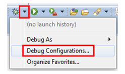
-
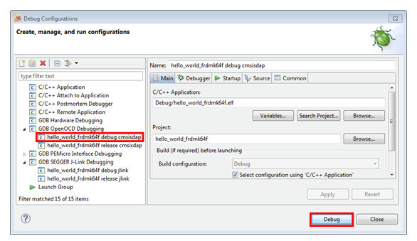
In the Debug Configurations dialog box, select debug configuration that corresponds to the hardware platform you’re using. For Windows or Linux users, select is the mbed/CMSIS-DAP option under OpenOCD For Mac users, select J-Link.
After selecting the debugger interface, click the "Debug" button to launch the debugger.
-
-
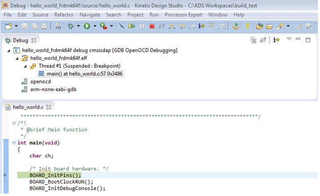
The application is downloaded to the target and automatically run to main():
-
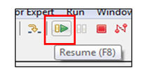
Start the application by clicking the "Resume" button:
-
The hello_world application is now running and a banner is displayed on the terminal. If this is not the case, check your terminal settings and connections.
Tera Term Tutorial
Tera Term Tutorial
Tera Term is a very popular open source terminal emulation application. This program can be used to display information sent from your NXP development platform's virtual serial port.
- Download Tera Term from SourceForge. After the download, run the installer and then return to this webpage to continue.
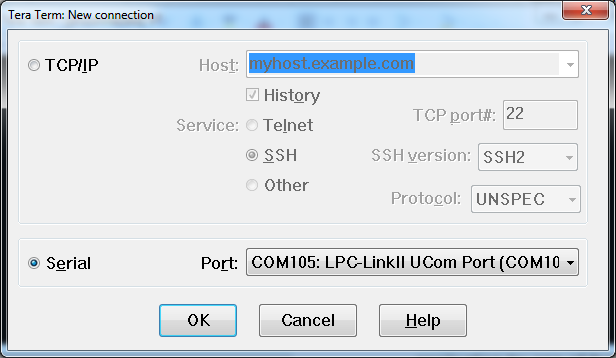
- Launch Tera Term. The first time it launches, it will show you the following dialog. Select the serial option. Assuming your board is plugged in, there should be a COM port automatically populated in the list.
- Configure the serial port settings (using the COM port number identified earlier) to 115200 baud rate, 8 data bits, no parity and 1 stop bit. To do this, go to Setup → Serial Port and change the settings.
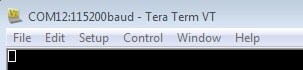
- Verify that the connection is open. If connected, Tera Term will show something like below in it's title bar.
- You're ready to go
PuTTY Tutorial
PuTTY Tutorial
PuTTY is a popular terminal emulation application. This program can be used to display information sent from your NXP development platform's virtual serial port.
- Download PuTTY using the button below. After the download, run the installer and then return to this webpage to continue.
- Launch PuTTY by either double clicking on the *.exe file you downloaded or from the Start menu, depending on the type of download you selected.
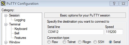
- Configure In the window that launches, select the Serial radio button and enter the COM port number that you determined earlier. Also enter the baud rate, in this case 115200.
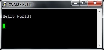
- Click Open to open the serial connection. Assuming the board is connected and you entered the correct COM port, the terminal window will open. If the configuration is not correct, PuTTY will alert you.
- You're ready to go
Support
Troubleshooting
Demo not working?
Did your board come in a box that looks like this?

No problem! Your board simply came in the old packaging and has a different out-of-box demo loaded into the flash memory.
You should be seeing the RGB LED toggling between each of the three colors; red, blue and green. It's OK to move onto the next step when you're ready.
Still not working?
Try proceeding to the next steps to get other example applications running on your board. If you still have problems, try contacting us through the NXP Community.
On this page
- 1.1
Get Started With the LPCXpresso51U68 Development Board - Demo.
- 1.2
Attach the USB Cable
- 1.3
Run the Out-of-Box Demo
- 2.1
Getting Started With the MCUXpresso SDK
- 2.2
Install your Toolchain
- 2.3
MCUXpresso Config Tools
- 2.4
Serial Terminal