- Analog Toolbox
- Getting Started with the PCA8561AHN-ARD Evaluation Board
Getting Started with the PCA8561AHN-ARD Evaluation Board
Contents of this document
-
Out of the Box
-
Get Hardware
-
Get Software
-
Configure Hardware
Sign in to save your progress. Don't have an account? Create one.
Purchase your PCA8561 18 × 4 LCD Driver Arduino® Shield
1. Out of the Box
The NXP analog product development boards provide an easy-to-use platform for evaluating NXP products. The boards support a range of analog, mixed-signal and power solutions. They incorporate monolithic integrated circuits and system-in-package devices that use proven high-volume technology. NXP products offer longer battery life, a smaller form factor, reduced component counts, lower cost and improved performance in powering state-of-the-art systems.
This page will guide you through the process of setting up and using the PCA8561AHN- ARD board.
1.1 Kit Content and Packing List
The PCA8561AHN-ARD contents include:
- Assembled and tested evaluation board in an anti-static bag
- Quick start guide
1.2 Assumptions
Familiarity with the I²C bus is helpful but not required.
1.3 Static Handling Requirements
This device is sensitive to electrostatic discharge (ESD). Therefore care should be taken during transport and handling. You must use a ground strap or touch the PC case or other grounded source before unpacking or handling the hardware.
1.4 Minimum System Requirements
This evaluation board requires a Windows PC workstation. Meeting these minimum specifications should produce great results when working with this evaluation board.
- Computer with Windows 10
- One USB port (either 3.0 or 2.0 or 1.1 compatible)
- One of three EVK boards (MIMXRT1050-EVK, LPC55S69-EVK, 8MMINILPD4-EVK) along with the associated firmware / GUI software
- USB cable for power and data connection between PC and EVK board (if not included in the EVK package)
2. Get Hardware
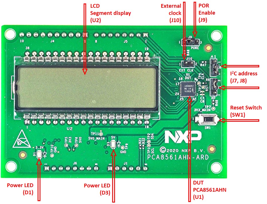
2.1 Board Features
- Equipped with Arduino Uno
R3port for direct connection with Arduino devices - On-board reset switch
- On-board jumpers for I²C address
- Fully compliant with IMXRT1050 EVK board, including GUI (Windows 10)
- Fully compliant with LPCXpresso55S69 dev. board, including GUI (Windows 10)
- Compliant with i.MX Mini LPDDR4 EVK board, including GUI (Windows 10)
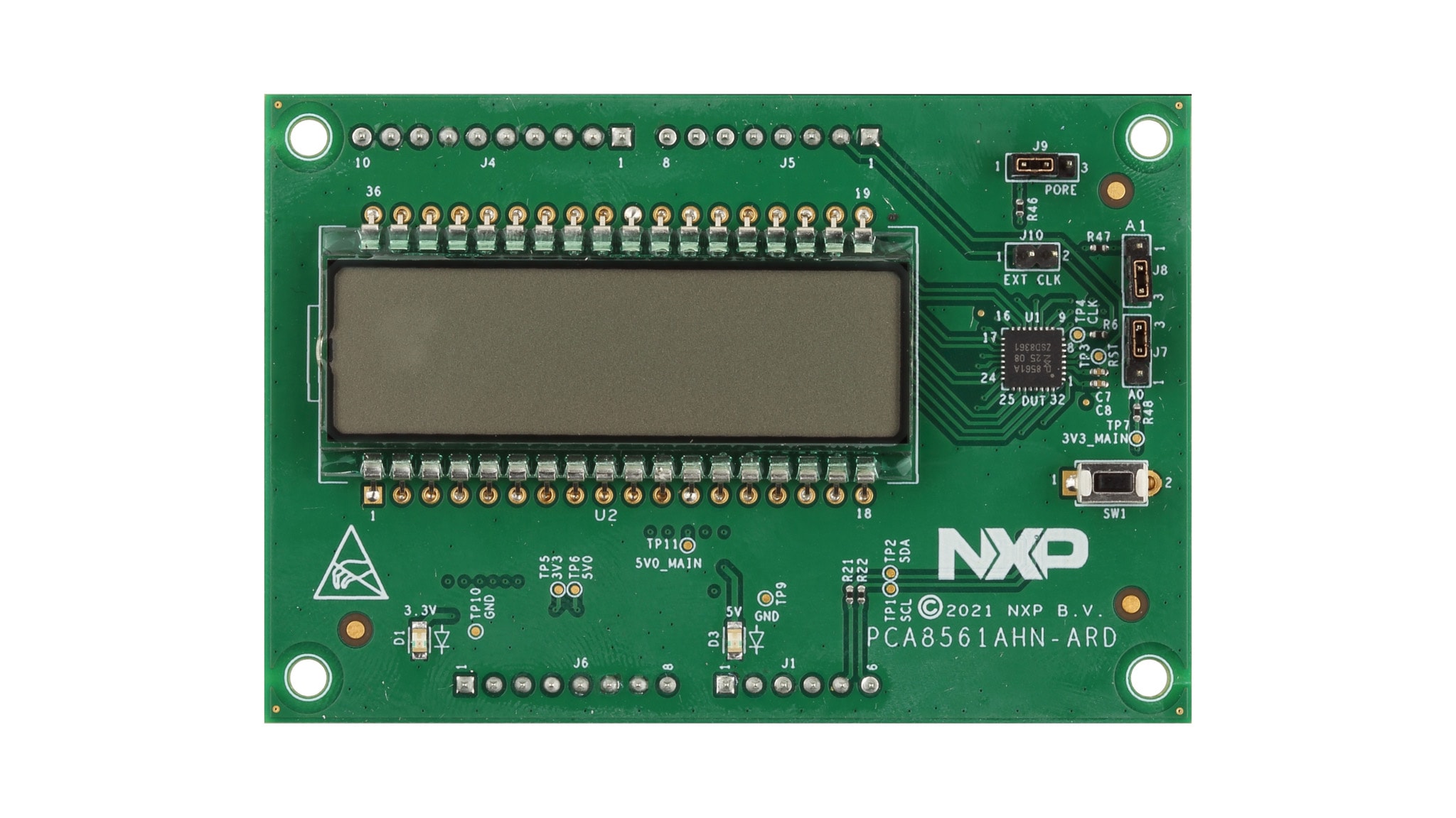
2.2 Board Description
The evaluation board is built around the PCA8561, automotive 18 x 4 LCD segment driver, produced by NXP Semiconductors. The evaluation board serves as a daughter card that can be connected through an Arduino port to various Arduino compatible (including original Arduino Uno R3) EVK / mother boards with the purpose of testing and measuring the characteristics of the PCA8561AHN device under test (DUT).
3. Get Software
3.1 Install and Configure Software Tools
PCA8561AHN-ARD evaluation board is designed and built as a daughter board able to work in conjunction with a mother board equipped with an Arduino port. The board was built to be fully compatible with the following NXP evaluation (EVK) boards:
- IMXRT1050 EVK board
- LPCXpresso55S69 development board
- i.MX 8M mini LPDDR4 EVK board
Each evaluation/development board benefits by firmware support which can be downloaded from NXP company site. Before starting, the EVK motherboard must be programmed with the corresponding firmware package. Additionally, a GUI application (Windows 10) is available for download from the NXP site, allowing rapid testing and operation of PCA8561AHN-ARD daughter board through one of above mentioned EVKs.
For details regarding installation of the EVK firmware and GUI host software on PC, please download EVK_Firmware_And_GUI_Install_Guide_For_Arduino_Boards.pdf instruction
file from NXP site. Once the software is installed, the first step is to select
the correct combination EVK – PCA8561AHN-ARD daughter card and then the
board can be controlled from the GUI interface.
4. Configure Hardware
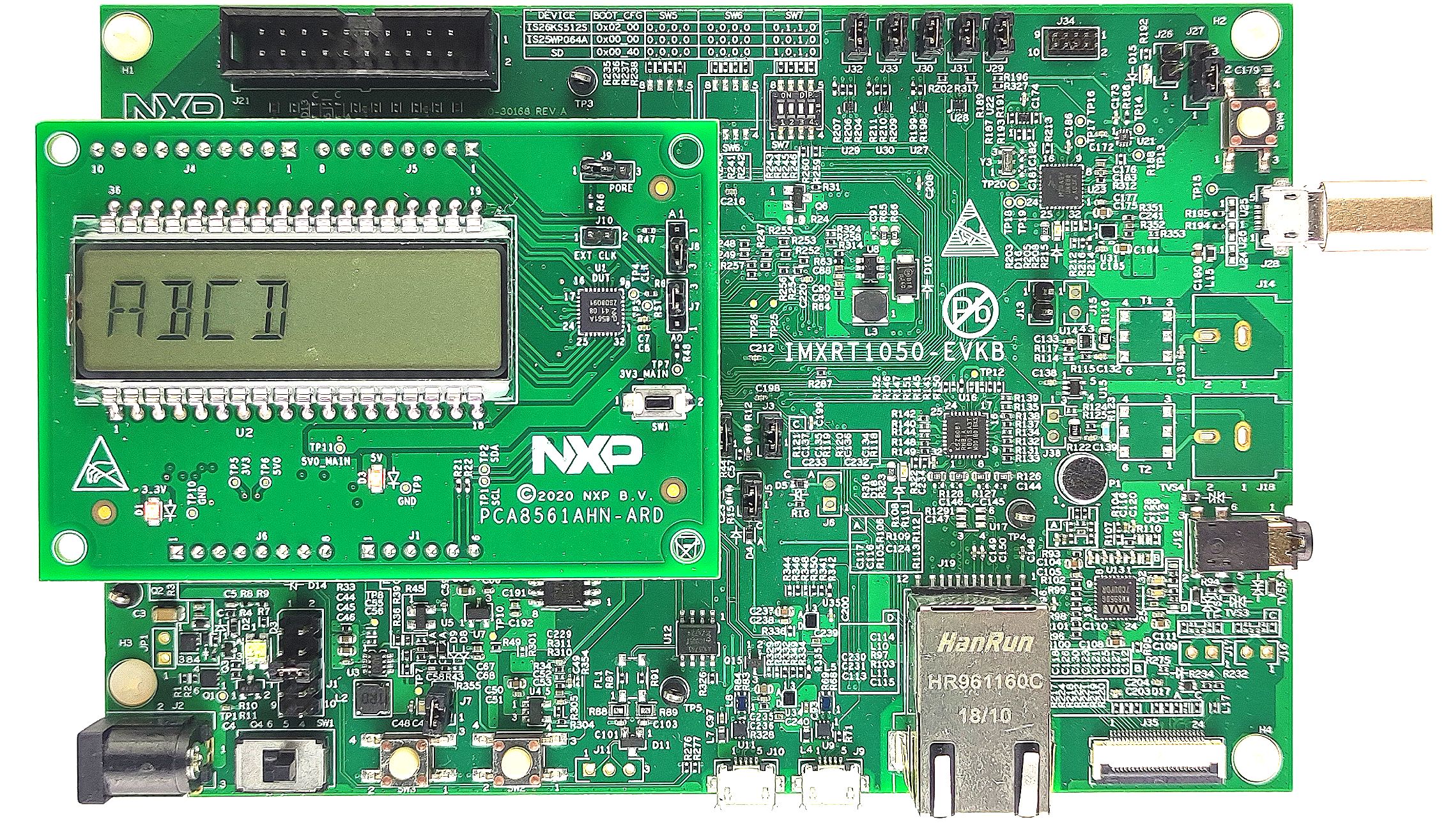
4.1 Board with an IMXRT1050 EVK
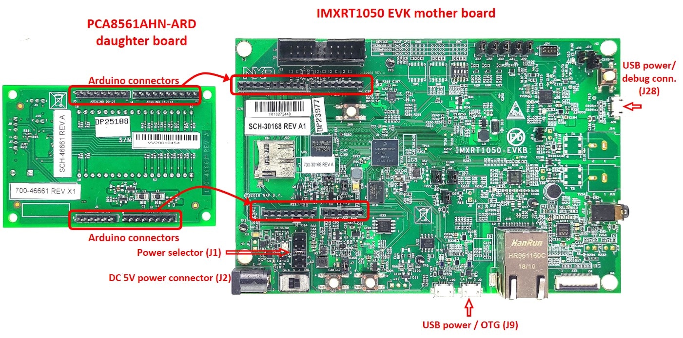
Figure 1 shows the required hardware for operation of the PCA8561AHN-ARD daughter board with IMXRT1050 EVK. The following items are necessary:
- One IMXRT1050-EVK board
- One PCA8561AHN-ARD daughter board
- One USB-A / USB Micro-b cable
- A PC with Windows 10 operating system
The IMXRT1050 EVK mother board can be powered by one of the three methods:
- Connecting an external 5.0 V DC power supply to the barrel power connector (
J2) on the board - Connecting a USB cable from the PC to the Micro-b USB connector (
J9) on the board -
Connecting a USB cable from the PC to the USB connector (
J28) on the board. When the PC is connected in this fashion, the USB port can simultaneously act as a debug interface. Therefore, by using a single USB cable connected toJ28, the EVK can be powered and at the same time linked to the PC for data exchange
The older USB ports (from PC) are not able to deliver the necessary current (500 mA). Before
establishing the communication, use an external power supply (connected to
J2).
From J1 on the EVK board (see Figure 1) the user can select the power configuration
for the mother board. For further details, refer to the MIMXRT1050 EVK
board hardware user’s guide.
To configure the hardware and workstation, complete the following procedure:
-
Configure the suitable power configuration of EVK (
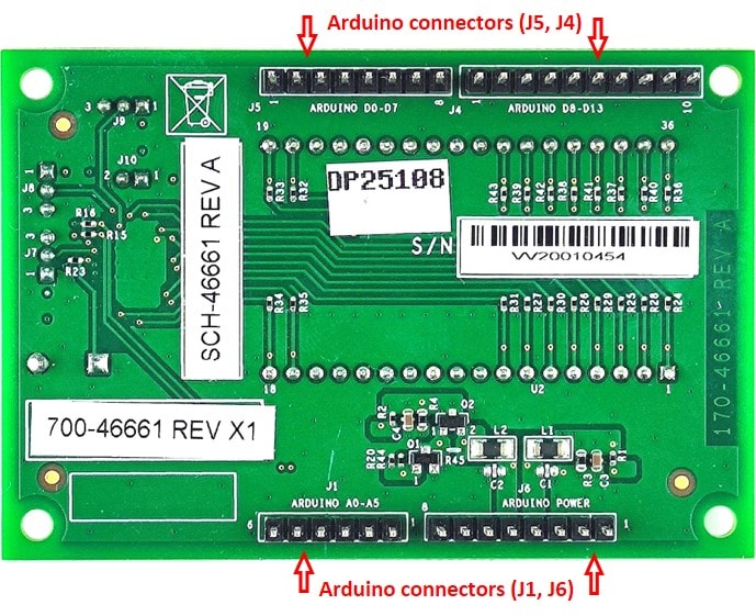
J1). If usingJ28for power supply, theJ1jumper shall be placed in position 5-6. If using an external power supply (connected toJ2), the jumperJ1will be placed in position 1-2 - Insert the PCA8561AHN-ARD daughter card on the Arduino connector of the EVK (see Figure 2)
- Using USB connector
J28, connect the EVK board to a USB port of the computer - Install the IMXRT1050 target firmware (download from NXP site and see UM11581, Arduino Arduino shields GUI and firmware installation manual for step-by-step instructions)
- Install GUI application (see UM11581, Arduino shields GUI and firmware installation manual)
- Open the GUI application to operate the device from the PC
Figure 2 shows the boards during the operation.
4.2 Board with an LPCXpresso55S69
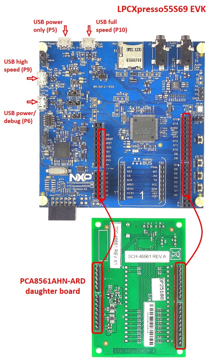
Figure 3 shows the required hardware for operation of the PCA8561AHN-ARD and LPCXpresso55S69 EVK board. This configuration consists of:
- One LPCXpresso55S69 EVK board
- One PCA8561AHN-ARD daughter board
- One USB-A / USB Micro-b cable
- A PC with Windows 10 operating system
The LPCXpresso55S69 development board is equipped with four USB Micro-b connectors:
P5, P6, P9 and P10. The board
can be powered through any USB port. Using P6 USB connector to connect the board to
the PC simplifies the start-up operation because P6 is designated for
debugging and the USB cable thus accomplishes two tasks at the same time: powering the board and
serving as a data link between the EVK board and PC. For more details
regarding power-up and operation of the LPCXpresso55S69 development board, see the
LPCXpresso55S69/LPCXpresso55S28 development board user manual.
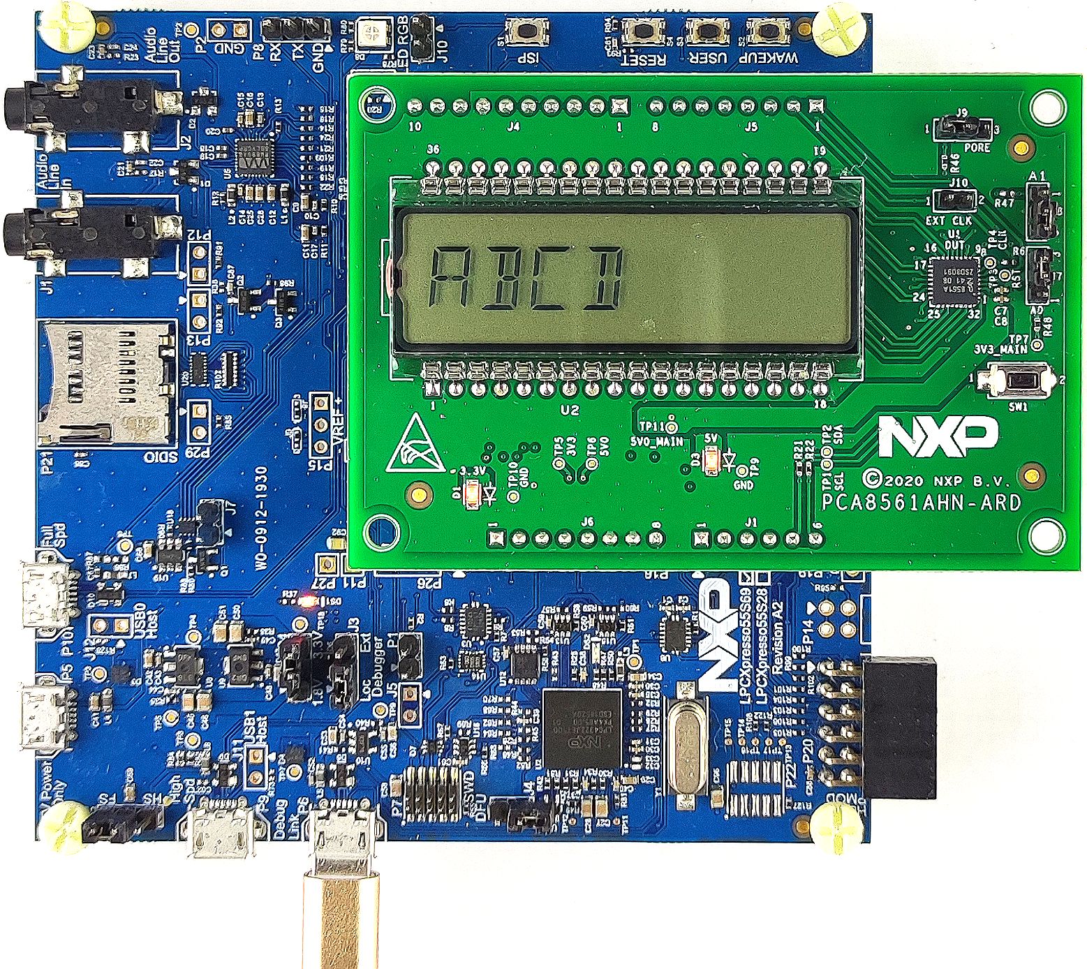
The following steps describe how to assemble, program and operate the configuration shown in Figure 3:
-
Insert the PCA8561AHN-ARD daughter card to
P16–P19connectors located on LPCXpresso55S69 development board (see the marked pins ofP16–P19, Figure 3). - Connect the development board using port
P6USB port of PC. - Install the LPCXpresso55S69 target firmware (download from NXP site and read the EVK_Firmware_And_GUI_Install_Guide_For_Arduino_Boards.pdf instruction file).
- Install GUI application on PC (see the instruction file called out in the previous step).
- Open the GUI application to operate the device from the PC.
Figure 3 shows the two boards in operation.
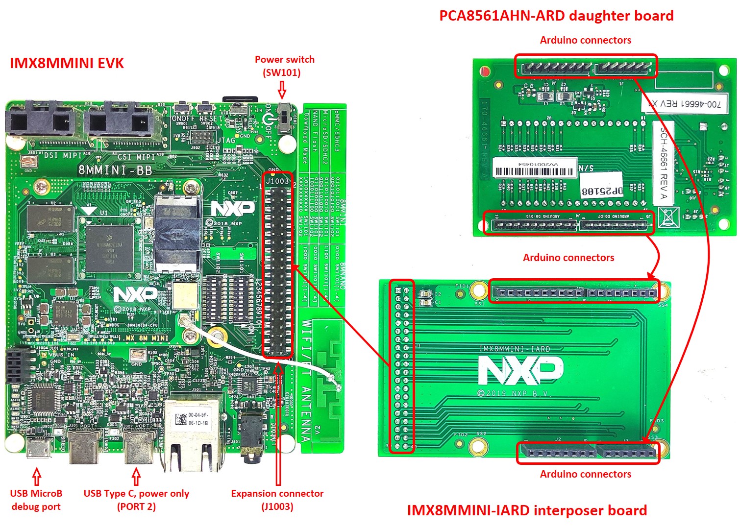
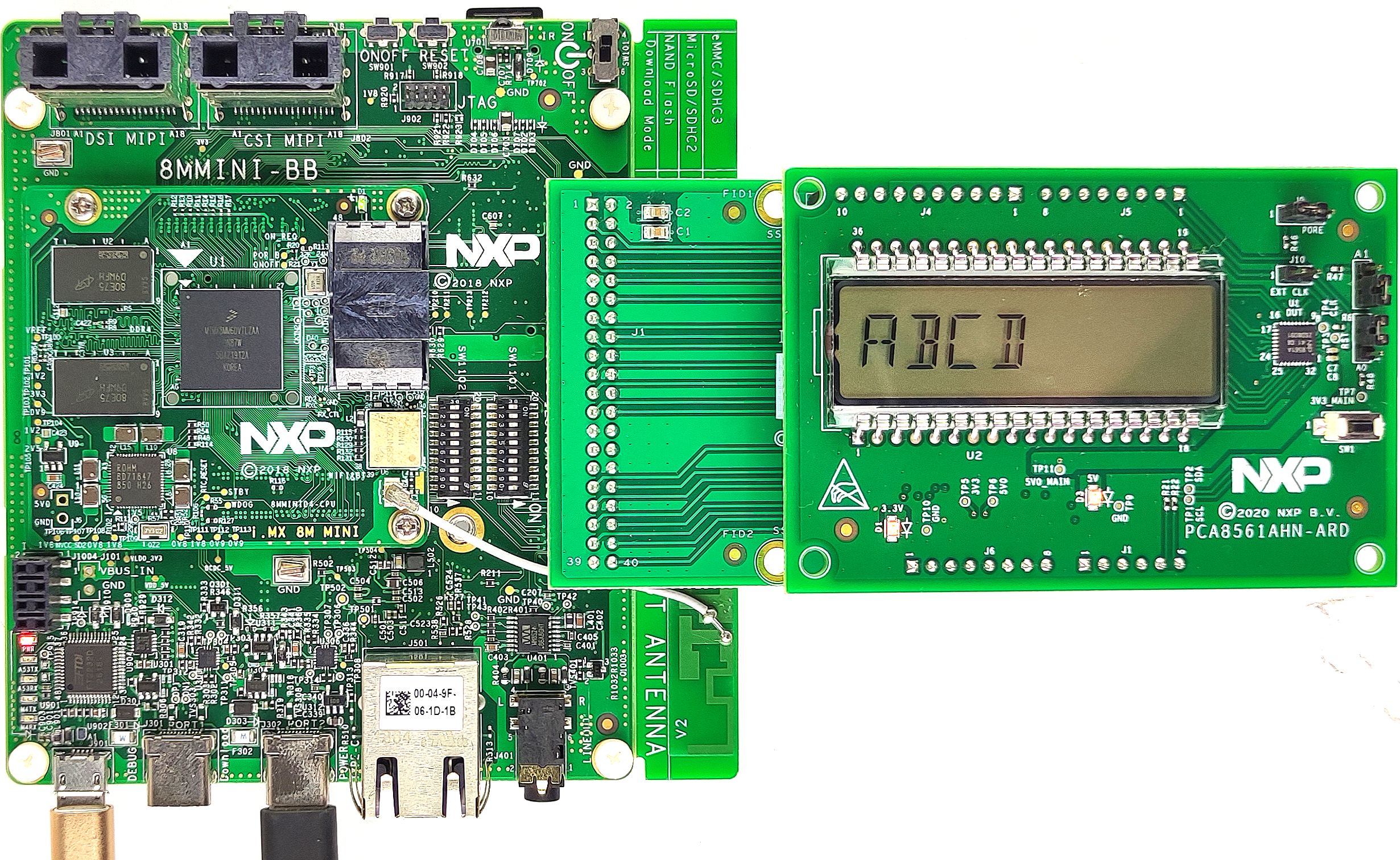
4.3 Board with i.MX 8M Mini LPDDR4 EVK
When an i.MX 8M Mini LPDDR4 EVK board is used with the PCA8561AHN-ARD board, a third board
(IMX8MMINI-IARD interposer board) must be used, especially designed and built
as an EVK – daughter board interconnection. The EVK board i.MX 8M Mini LPDDR4 is not equipped
with an Arduino port; instead it has a 2 x 20 pin expansion connector
(J1003, see i.MX 8M Mini LPDDR4 EVK user manual). J1003 is a
multipurpose port, containing various digital I/O lines, including specialized
I2C and SPI buses. Starting from the expansion connector pin chart, an Arduino port interposer
board was developed, with the role of signal-to-signal bridge between the
2 x 20 connector pins on the i.MX 8M Mini LPDDR4 EVK and the mated connectors of the Arduino
port present on the PCA8561AHN-ARD daughter board.
To operate the setup, along with the EVK and the daughter board, a third board must be included in the setup assembly. Figure 5 shows the necessary boards and how these boards are connected. The configuration consists of:
- One i.MX 8M Mini LPDDR4 EVK board
- One PCA8561AHN-ARD daughter board
- One IMX8MMINI-IARD interposer board
- One USB-A / USB-C cable
- One USB-A / USB Micro-b cable
- A PC with Windows 10 operating system
It is recommended to attach the PCA8561AHN-ARD to the Arduino connectors of the IMX8MMINI-IARD
interposer board first and then the resulting assembly to the i.MX 8M
Mini LPDDR4 EVK. This can be done by plugging J1 connector located on the
interposer board to J1003 connector on the EVK.
To power-up the EVK, a USB-C type cable connected to PORT 2 of the EVK is used. The power switch
SW101 on the EVK board must be set to ON position to
power-up the setup. Data communication is achieved by routing a separate USB (Micro-b type)
cable from a USB port on the PC to debug port (J901) on the EVK
(see Figure 5 and Figure 6).
The user may find details regarding power-up and operation of the setup assembly in 8MMINILPDDR4-EVK user manual and IMX8MMINI-IARD user manual. The files can be downloaded from www.nxp.com.
To configure and operate the setup, follow the below steps:
- Insert the PCA8561AHN-ARD onto the IMX8MMINI-IARD interposer board Arduino connectors (located on the top side).
-
Attach IMXMMINI-IARD connector plug
J1(located on the bottom of the board) intoJ1003expansion board located on the top side of i.MX 8M Mini LPDDR4 EVK (see Figure 6). - Power-up the EVK board using a USB Type C cable attached to PORT
2. - Connect the EVK to the PC, using a USB Micro-b cable, attached to
J901debug port. - Place
SW101in ON position to power up the boards. - Install the MIMXRT1050 target firmware (download UM11581, Arduino shields GUI and firmware installation manual from NXP site).
- Install GUI application on the PC (see the instruction file referred in the above step).
- Open the GUI application to operate the device from the PC.
4.4 Board with Another Device
The PCA8561AHN-ARD daughter board can be operated with other EVK board, which has an Arduino port. There are two options to connect the board: using other EVK equipped with an Arduino port and an EVK without Arduino port. In the first case, a firmware shall be developed according with PCA8561 specifications, and then simply attach PCA8561AHN-ARD daughter board to the EVK to operate the board. In the second case, using the pin chart of Arduino connectors, make the necessary electrical connections (for power, I²C-bus and control lines) and develop the desired firmware, assuring that it is compliant with IC specifications. Use PCA8561 data sheet to read details about internal registers of the DUT IC and data exchange between internal controller and the EVK. Assure for correct electrical connections and avoid data conflicts on the signal lines to prevent IC damage.
Design Resources
Board Information
Additional Resources
References
In addition to our PCA8561: Automotive 18 X 4 LCD Segment Driver, you may also want to visit:
Freedom pages:
- i.MX RT1050 Evaluation Kit
- LPCXpresso55S69 Development Board
- Evaluation Kit for the i.MX 8M Mini Applications Processor
Hardware pages:
Software pages: