Getting Started with USB-KW019032
Contents of this document
-
Plug It In
-
Get Software
-
Build, Run
Sign in to save your progress. Don't have an account? Create one.
Purchase your USB-KW019032 | MKW01Z128CHN | Wireless
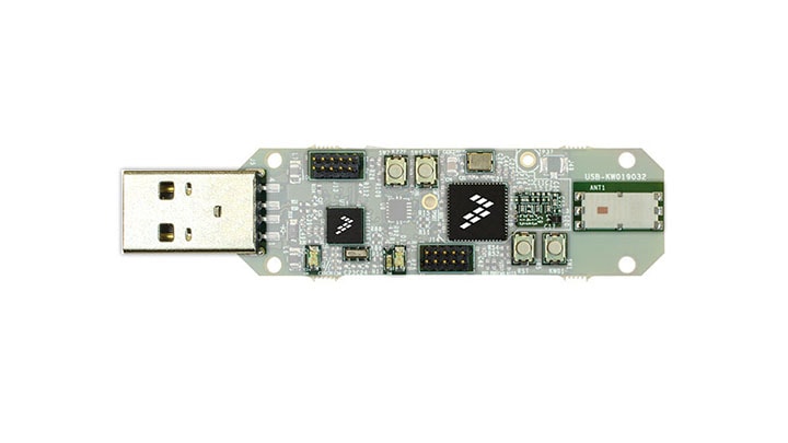
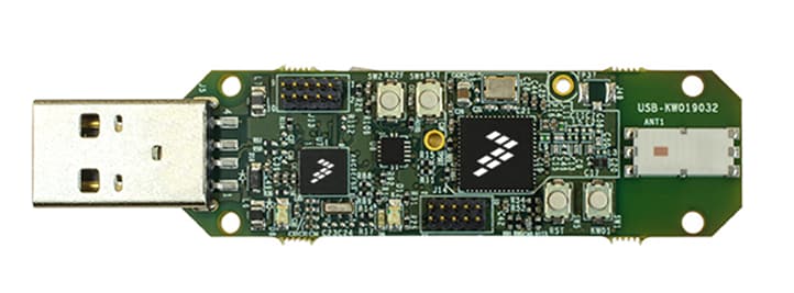
1. Plug It In
Let's take your USB-KW019032 for a test drive.
2. Get Software
2.1 Installing Software for the USB-KW019032
In this step, we are going to guide you through the process to get the required software to enable the USB-KW019032 dongle as a IEEE 802.15.4 sniffer. You can also use the USB-KW019032 as a development platform. Select the option you want to accomplish with your USB-KW019032.
Choose a Development Path:
USB-KW019032 Sniffer
Download Test Tool for Connectivity Products
Test Tool for Connectivity Products is a set of graphical user interface modules and applications for testing and deploying Kinetis-W wireless. This tool offers a protocol analyzer for the Kinetis-W family and a Kinetis Firmware Loader.
Get Test Tool for Connectivity Products
Download the driver for your USB-KW019032
Download and install the driver for your USB-KW019032. Before running the driver installer, you MUST have the board plugged in to your PC.
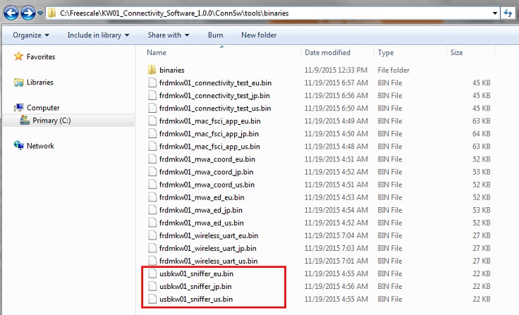
Download the sniffer application
This step only applies in case you previously downloaded other demo to your board and you require to re-program the board with the snifer application.
You can find this binary and the versions for the EU and JA bands of the sniffer app in the next path after installing the KW01 Connectivity Software v1.0.0:
How to download the sniffer application into the USB board?
- Connect your USB-KW019032 to your PC, MBED (E:) will be detected
- Drag and drop the
Sniffer_usbkw01_US.binto MBED (E:) using the MSD capabilities of the CMSIS-DAP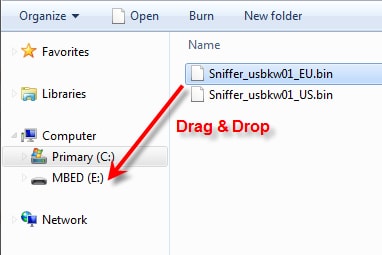
- MBED (E:) will blink, disconnect the board, connect it again and the new firmware will start to run in the KW01
USB-KW019032 Development Platform
Installing software for the USB-KW019032
In this step, you will be guided to download the software and tools required to build and run the connectivity solutions.
Download KW01 Connectivity Software
The KW01 Connectivity Software package integrates the Kinetis Software Development Kit 1.3 and all the wireless connectivity stacks required to develop your solution using IEEE 802.15.4 and SMAC wireless connectivity stacks.
Click below to download the KW01 Connectivity Software v1.0.0 for your computer.
Get KW01 Connectivity Software
Install Your Toolchain
IAR Embedded Workbench for Arm ® (EWARM) version 7.40.2 or later is the development toolchain used to deploy software applications using the NXP Connectivity stacks. NXP provides example EWARM workspace projects for you to start your development.

Get IAR Embedded Workbench for Arm
Want to use a different toolchain?
Right now, the only supported toolchain is IAR Embedded Workbench for Arm; we are currently working on the enablement of NXP KDS for the Connectivity stacks.
PC Configuration
Many of the example applications output data over the MCU UART so you'll want to make sure that the driver for the board's virtual COM port is installed. Before you run the driver installer, you MUST have the board plugged in to your PC.
With the serial port driver installed, run your favorite terminal application to view the serial output from the MCU's UART. Configure the terminal to 115200 baud rate, 8 data bits, no parity and 1 stop bit. To determine the port number of the USB-KW019032's virtual COM port, open the device manager and look under the "Ports" group.
Not sure how to use a terminal application? Try one of these tutorials: Tera Term Tutorial, PuTTY Tutorial
3. Build, Run
3.1 Configure Your Sniffer Tool
USB-KW019032 comes pre-programmed with a sniffer application. Once all the required software is installed in the PC. You are ready to start sniffing your IEEE 802.15.4 applications.
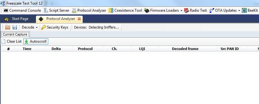
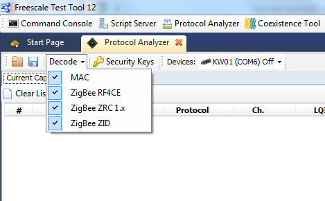
How to use the Test Tool's Protocol Analyzer?
- Connect the USB KW019032 to PC
- Open the undefined protocol analyzer tab
- The undefined Protocol Analyzer should automatically detect the KW01 sniffer. If not, close the tab, unplug the board, plug it back and re-open the tab. If this doesn’t work, try restarting undefined Test Tool.undefined
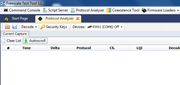
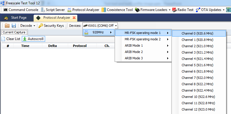
- To start “sniffing” the desired channel, click the arrow down button from undefined undefined Devices: KW01 (COMx) Off undefined and select the desired mode and channel.undefined
- The tab will change to ON meaning that KW01 will "sniff" on the specified channel. To select other channel, click the tab again and it will switch back to Off. Then select a new channel
Tera Term Tutorial
Tera Term Tutorial
Tera Term is a very popular open source terminal emulation application. This program can be used to display information sent from your NXP development platform's virtual serial port.
- Download Tera Term from SourceForge. After the download, run the installer and then return to this webpage to continue
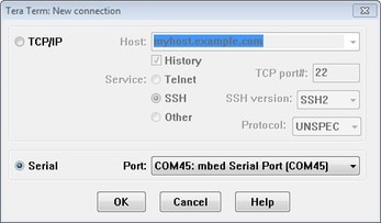
- Launch Tera Term. The first time it launches, it will show you the following dialog. Select the serial option. Assuming your board is plugged in, there should be a COM port automatically populated in the list
- Configure the serial port settings (using the COM port number identified earlier) to 115200 baud rate, 8 data bits, no parity and 1 stop bit. To do this, go to Setup → Serial Port and change the settings
- Verify that the connection is open. If connected, Tera Term will show something like below in it's title bar
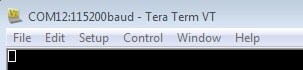
You're ready to go.
PuTTY Tutorial
PuTTY Tutorial
PuTTY is a popular terminal emulation application. This program can be used to display information sent from your NXP development platform's virtual serial port.
- Download PuTTY using the button below. After the download, run the installer and then return to this webpage to continue
- Launch PuTTY by either double clicking on the *.exe file you downloaded or from the Start menu, depending on the type of download you selected
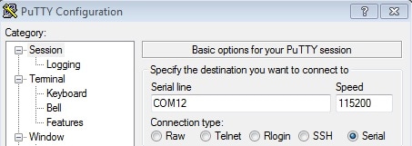
- Configure In the window that launches, select the Serial radio button and enter the COM port number that you determined earlier. Also enter the baud rate, in this case 115200
- Click Open to open the serial connection. Assuming the board is connected and you entered the correct COM port, the terminal window will open. If the configuration is not correct, PuTTY will alert you
You're ready to go.
Design Resources
Board Documents
Chip Documents
Support
Support
Learn more about the USB-KW019032 with design tips, training documents, and the NXP Community. If you need additional help, contact NXP Support.