Safe Assure® (Functional Safety)
When it comes to functional safety, NXP stands for quality and reliability. Our SafeAssure program simplifies system-level safety requirements in accordance with ISO 26262.
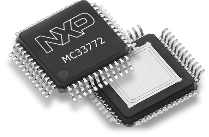
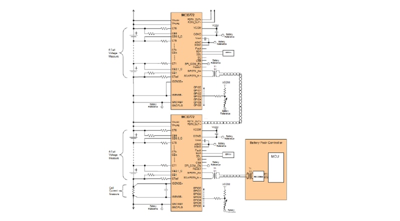
The MC33772 is a Li-Ion battery cell controller IC designed for automotive and industrial applications such as HEV, EV, ESS, UPS systems. It has been chosen as one of EDN’s Hot 100 products for 2015! featuring:
Datasheet, Safety Manual and Application Hint available with a non-disclosure agreement (NDA). For additional information, contact your local NXP Sales Office.
| Parameter | MC33771B | MC33771C | MC33772B | MC33772C |
| Voltage Channels | 7..14 | 7..14 | 3..6 | 3..6 |
| Supply VRange (Max) | 9.6 V..61.6 V (75 V) | 9.6 V..61.6V (75 V) | 6 V..30 V (40 V) | 6 V..30 V (40 V) |
| Cell Input Voltage Range | -0.3 V to 5 V | -0.3 V to 5 V | -0.3 V to 5 V | -0.3 V to 5 V |
| Measurement Error | ± 0.8 mV (Vcell =3.3 v Ta = 25°c) | ± 0.8 mV (Vcell =3.3 v Ta = 25°c) | ± 0.8 mV (Vcell =3.3 v Ta = 25°c) | ± 0.8 mV (Vcell =3.3 v Ta = 25°c) |
| Total Measurement Error (After aging: MLS3 and 1000h HTOL) |
± 3.9 mV | ± 3.9 mV | ± 3.9 mV | ± 3.9 mV |
| Vpwr=9.6V..61.6V, Vcell=1.5V..4.3V, -40~85°C |
Vpwr=9.6V..61.6V, Vcell=1.5V..4.3V, -40°C..85°C |
Vpwr=6V..30V, Vcell=1.5V..4.3V, -40~85°C |
Vpwr=6V..30V, Vcell=1.5V..4.3V, -40~85°C |
|
| Measurement averaging | No | Configurable Averaging Samples 2n n=0..8, (1,2,4,..256) |
No | Configurable Averaging Samples 2n n=0..8, (1,2,4,..256) |
| Functional Safety |
ASIL C ASIL D Compliance |
ASIL C ASIL D Compliance |
ASIL C ASIL D Compliance |
ASIL C ASIL D Compliance |
| Isolated communication Speed | 2 Mbps | 2 Mbps | 2 Mbps | 2 Mbps |
| Communication Isolation | Inductive | Inductive, Capacitive | Inductive | Inductive, Capacitive |
| Max Nodes per Daisy Chain | 15 | 63 | 15 | 63 |
| CRC Bit | 8 | 8 | 8 | 8 |
| Comms bit | 40 | 48 | 40 | 48 |
| Integrated Balancing | <300 mA, Timer | <300 mA, Timer | <300 mA, Timer | <300 mA, Timer |
| Balancing sleep mode | Yes | Yes | Yes | Yes |
| GPIO / Analog measurement inputs | 7 | 7 | 7 | 7 |
| I²C Controller | EEPROM Only | EEPROM Only | EEPROM Only | EEPROM Only |
| Current Channels | 1 | 1 | 1 | 1 |
| Coulomb counter | 1 | 1 | 1 | 1 |
| Package | 64-pin LQFP-EP (-40~105°C) | 64-pin LQFP-EP (-40~105°C) | 48-pin LQFP-EP (-40~105°C) | 48-pin LQFP-EP (-40~105°C) |
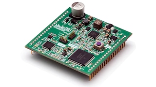
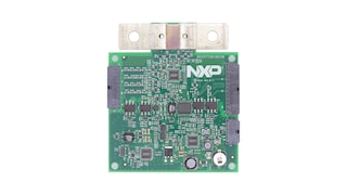
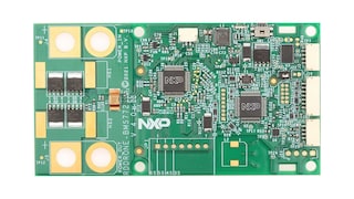
Battery management systems (BMS) solutions for automotive and industrial applications including 12 V, 48 V, high-voltage and battery pack monitoring applications.
When it comes to functional safety, NXP stands for quality and reliability. Our SafeAssure program simplifies system-level safety requirements in accordance with ISO 26262.
Participating products are available for a minimum of 10 years. Designated participating products developed for the automotive, telecom and medical segments are available for a minimum of 15 years.
|
|
|
|
|
|
|
|---|---|---|---|---|---|
|
|
|
|
|
|
|
|
|
|
|
|
|
|
|
|
|
|
|
|
|
|
|
|
|
|
|
|
|
|
|
|
|
|
|
|
|
|
|
|
|
|
|
|
|
|
|
|
|
|
|
|
|
|
|
|
|
|
|
|
|
|
|
|
|
|
|
|
|
|
Quick reference to our documentation types
9 documents
Compact List
Receive the full breakdown. See the product footprint and more in the eCad file.
1-5 of 12 hardware offerings
Quick reference to our software types.
2 software files
Note: For better experience, software downloads are recommended on desktop.